Background
The present invention relates to switch structures and electronic/electric component part installing structures suited for application to various electronic equipment, such as electronic musical instruments, and electronic musical instruments including such switch structures or electronic/electric component part installing structures.
The various conventionally-known electronic equipment, such as electronic keyboard musical instruments, includes various operating switches provided on an operation panel. Among examples of such switches are switch structures disclosed in Japanese Patent Application Laid-open Publication No. HEI-11-39994 (hereinafter referred to as "patent literature 1") and Japanese Patent No. 2650179 (hereinafter referred to as "patent literature 2"). The switch structure disclosed in patent literature 1 includes a plate-shaped operation panel having holes through which controls (or operators) are partly exposed out of the holes, a circuit board disposed under the operation panel, fixed contacts provided on the circuit board, the controls each vertically movably mounted to the underside of the operation panel via a flexible hinge portion, actuators each having a projecting shape and provided on the underside of a corresponding one of the controls; contact rubber members each provided on the circuit board and formed of resilient resin for being depressed by a corresponding one of the actuators; and movable contacts each provided on the underside of a corresponding one of the contact rubber members. The operation panel having the controls mounted to its underside and the circuit board having the contact rubber members on its topside are fixed in spaced apart relation to each other via spacers. As any one of the controls projecting out of the holes is depressed by a user's finger or the like, the contact rubber member corresponding to the depressed control is depressed and resiliently deformed by the actuator of the control. Thus, the movable contact of the contact rubber member contacts a corresponding one of the fixed contacts on the circuit board, so that a corresponding switch is turned on.
In the switch structure disclosed in patent literature 1, the actuator of each of the controls is disposed over the corresponding contact rubber member provided on the circuit board, and the contact rubber member is constantly slightly pressed by the control against the circuit board. Because the control is vertically movably provided via the flexible hinge portion, the contact rubber member and the control is slightly movable relative to the circuit board and operation panel rather than being completely fixed to the circuit board and operation panel. However, in a case where the switch structure disclosed in patent literature 1 is provided in an electronic keyboard instrument that audibly generates sounds through a speaker or the like, a casing of the electronic keyboard instrument would slightly vibrate depending on sounds generated. In such a case, vibrating sound (so-called RUB & BUZZ) may undesirably occur in the controls and contact rubber members due to the slight vibration propagating from the casing to the circuit board and operation panel. As one approach for reducing the vibrating sound, it may be conceivable to apply pre-tension to the hinge portions so that the contact rubber members are mounted on the circuit board in a slightly pressed state. With such an approach, however, deformation may undesirably occur in the contact rubber members, preventing appropriate ON/OFF operation of the contacts.
Further, the switch structure disclosed in patent literature 1, the controls partly exposed out of the holes and the contact rubber members to be pressed by the controls are constructed as separate parts, which would thus result in a great number of necessary component parts of the switch structure and prevent simplification of the switch structure. In addition, the great number of component parts would require much time and labor in assembly work and can prevent simplification of manufacturing steps of the switch structure.
Further, the switch structure disclosed in patent literature 2 is a key switch structure of an electronic keyboard instrument which includes: a keyboard having a plurality of keys, actuators each having a projecting shape and provided on the underside of a corresponding one of the keys; and a contact rubber member formed of a resilient material, such as rubber, and disposed between the actuators and a circuit board having fixed contacts disposed under the keyboard. The contact rubber member includes a plate-shaped base section provided on the circuit board, upwardly-convexed cup portions provided on the base section and spaced from each other at predetermined intervals, and movable contacts each provided on the underside (inner bottom surface) of a corresponding one of the cup portions. Further, small mounting projections are provided on the base section of the contact rubber member and fixedly inserted in corresponding small fixing holes formed in the circuit board.
In the switch structure disclosed in patent literature 2, the contact rubber member is fixedly mounted on the circuit board by means of the small mounting projections, and the contact rubber member is pressed against the circuit board via the actuator of the key abutted against the upper surface of the cup portion. Thus, even if the casing of the electronic keyboard instrument slightly vibrates due to sound audibly generated through a speaker and propagates form the casing to the circuit board and operation panel, it is possible to suppress, to some degree, vibrating sound occurring in the contact rubber member. However, with the switch structure disclosed in patent literature 2, where the entire base section including portions located between the adjoining cup portions is disposed in face contact with the upper surface of the circuit board, vibrating sound (Rub & Buzz) can occur between the base section and the circuit board due to the slight vibration.
Further, with the switch structure disclosed in patent literature 2, the small mounting projections, provided on the contact rubber member as a structure for fixing the rubber member, can suppress, to some degree, vibrating sound of the contact rubber member. However, because the contact rubber member includes a rubber sheet of a thin plate shape having not only a multiplicity of contacts integrally formed thereon but also the above-mentioned small mounting projections formed thereon at predetermined intervals, the contact rubber member would undesirably become complex in shape. Besides, because operation for fixedly inserting the small mounting projections into the small holes of the circuit board, much time and labor would be required for assembling the switch structure.
Summary of the invention
In view of the foregoing prior art problems, it is an object of the present invention to provide an improved switch structure and electronic/electric component part installing structure which, with a simple construction requiring only a minimized number of necessary component parts, can effectively suppress vibrating sound caused due to slight vibration of the component parts, as well as an electronic musical instrument including such a switch structure or electronic/electric component part installing structure.
In order to accomplish the above-mentioned object, the present invention provides an improved switch structure (10), which comprises: a circuit board
including a switch section
where at least a part of component parts (61a, 61b) constituting a switch contact
is provided; an intermediate member
including: a base section
provided in a corresponding relation to the switch section
on said circuit board
and including a held portion (43); a operator portion
operable to drive said switch section (62); and a resilient connection portion
resiliently connecting the operator portion
to said base section (45); a panel member
including a plate-shaped body portion (21), an opening portion
formed in the body portion
for positioning therein the operator portion (47), and a cylindrical holding portion
provided on the lower surface (20b) of the body portion
around the opening portion
and projecting toward the circuit board (60); and a fixing member
which fixes together the panel member
and the circuit board
in face-to-face pressed engagement with the intermediate member
sandwiched between the panel member
and the circuit board (60). The operator portion
of the intermediate member
is partly exposed out of the opening portion
of the panel member (20), the held portion
of the intermediate member
is held fitted in the holding portion
of the panel member (20). Note that the terms "upper", "lower", "upper surface", "lower surface", etc. are used herein to refer to directions as viewed when the panel member, intermediate member and circuit board are disposed in a horizontal orientation and in vertically superposed relation to one another.
According to the switch structure of the present invention, the intermediate member can be reliably fixed relative to the panel member and circuit board because the held portion of the intermediate member is held fitted in the holding portion of the panel member. With such arrangements, the present invention can effectively suppress or prevent generation of vibrating sound (Rub & Buzz) between the intermediate member and the panel member and circuit board even in a situation where slight vibration transmits to the panel member and circuit board.
Further, with the held portion of the intermediate member fittedly held by the holding portion of the panel member, the operator portion inserted in the opening portion of the panel member can also be positioned appropriately. Thus, the present invention can achieve an enhanced design of the operation panel section etc. Further, because the intermediate member includes the operator portion having both a function as a control (operator) for being depressed by a user and a function as a driver for driving the switch section, the present invention can reduce or minimize the number of necessary component parts and simplify necessary steps for assembling the switch structure, as compared to the conventionally-known counterparts.
Preferably, in the switch structure of the present invention, the base section
may further include a fixed portion
at a lower end of the held portion
so that the held portion
is formed integrally with an upper end of the fixing portion (41), the fixed portion
having a lateral size larger than the held portion
to form a step at the upper end of the fixing portion (41), and the step of the fixing portion
is sandwiched between a lower end of the holding portion
of said panel member
and an upper surface of said circuit board (60). In this way, where the fixing portion of the intermediate member is sandwiched between the lower end of the holding portion of the panel member and the upper surface of the circuit board, the intermediate member can be even more reliably fixed relative to the panel member and circuit board. Further, with the fixing portion of the intermediate member sandwiched between the lower end of the holding portion of the panel member and the upper surface of the circuit board, there is no need for any separate member for fixing the intermediate member to the circuit board. In this way, it is possible to not only simplify the shape of the intermediate member but also facilitate assembling of the switch structure.
Preferably, in the switch structure of the present invention, the held portion
of the base section
of the intermediate member
has a cylindrical outer shape, and the fixed portion
has a diameter larger than the held portion
to form a circular step at the upper end of the fixing portion
as said step. Further, preferably, in the switch structure of the present invention, the base section
is provided in a positional corresponding relation to an outer periphery of the switch section
on said circuit board (60).
Preferably, in the switch structure of the present invention, the circuit board
includes a plurality of the switch sections
disposed at a predetermined interval, the intermediate member
including a plurality of the base sections
and a plurality of the operator portions
corresponding to individual ones of the plurality of the switch sections (62), the panel member
having a plurality of the opening portions
corresponding to individual ones of the plurality of the operator portions (47). Further, the intermediate member
further includes a connecting portion
interconnecting the base sections
disposed along the respective outer peripheries of adjoining ones of the operator portions (47), the connecting portion
being formed in such a manner that a gap (A) is defined between the connecting portion
and the upper surface (60a) of the circuit board (60). Because the connecting portion interconnecting the fixing portions corresponding to the plurality of the switch sections is disposed out of contact with, or spaced from, the circuit board, it is possible to prevent generation of vibrating sound in the gap between the connecting portion and the circuit board. In this way, the present invention can effectively prevent generation of vibrating sound between a plurality of switches that has been a problem with the conventionally-known counterparts.
Further, preferably, in the switch structure of the present invention, the component parts constituting the switch contact
include a fixed contact (61a) provided in the switch section
of the circuit board
and a movable contact (61b) provided on the lower surface (47b) of the operator portion (47). In response to depressing operation on the operator portion (47), switching is effected by the movable contact (61b) being brought into contact with the fixed contact (61a). Alternatively, the component parts constituting the switch contact
may include a push button switch (61c) provided in the switch section
and activatable by being pressed by a user. In response to depressing operation on the operator portion (47), switching is effected by the lower surface (47b) of the operator portion
depressing the push button switch (47).
Further, preferably, in the switch structure of the present invention, the intermediate member
includes a surrounding portion
in the form of a cylindrical projection provided along the outer periphery of the held portion
and surrounding the outer periphery of the holding portion
of the panel member (20), and a recess portion
provided between the held portion
and the surrounding portion
for insertion therein of the lower end (52b) of the holding portion (25), and the lower end (25b) of the holding portion
is disposed in the recess portion (54), with the held portion
held fitted on the holding portion (25), so that the surrounding portion
overlaps the outer periphery of the holding portion (25). Because the lower end of the holding portion is disposed in the recess portion, with the held portion held fitted on the holding portion, so that the surrounding portion overlaps the outer periphery of the holding portion, the surrounding portion can seal up between the lower end of the holding portion and the fixing portion of the intermediate member. Thus, even when liquid has passed through the opening portion toward the circuit board, it is possible to prevent the liquid from entering the switch portion of the circuit board. In this way, the present invention can perform a waterproof function. Also, the present invention can prevent foreign substances, such as dust, from entering the switch portion from the upper surface side of the panel member.
Further, preferably, in the switch structure of the present invention, at least a part of the operator portion (47-2) is formed as a transparent portion (47-2) that is transparent or semitransparent. The switch structure of the present invention further includes a light emitting element (L) provided on the circuit board
in the switch section
in such a manner that emitted light of the light emitting element (L) passes through the transparent portion (47-2) so as to be radiated to the upper surface (47-2a) of the operator portion (47-2). With such arrangements, the present invention allows the switch structure to perform a light emitting function, by just mounting the light emitting element on the circuit board. As a result, the present invention can achieve an enhanced convenience of the switch structure with a simple construction.
According to another aspect of the present invention, there is provided an electronic/electric component part installing structure, which comprises: a circuit board
including a plurality of electronic component part installing sections (62, 62-2) in each of which an electronic/electric component part (61, L) is provided; an intermediate member
including: a plurality of base sections
each provided in a corresponding relation to any one of the electronic component part installing sections (62, 62-2) on said circuit board (60), each of the base sections
including a held portion (43); a plurality of operator portions (47, 47-2) each provided over a corresponding one of the electronic component part installing sections (62, 62-2); and a plurality of connection portions
each connecting a corresponding one of the operator portions (47, 47-2) to a corresponding one of the base sections (45); a panel member
including a plate-shaped body portion (21), a plurality of opening portions
each formed in the body portion
in a corresponding relation to any one of the operator portions (47, 47-2) for positioning therein the corresponding operator portion (47, 47-2), and a plurality of holding portions
each provided on a lower surface of the body portion around a corresponding one of the opening portions
and projecting toward said circuit board (60); and a fixing member
which fixes together the panel member
and the circuit board
in face-to-face pressed engagement with the intermediate member
sandwiched between the panel member
and the circuit board (60). Each of the operator portion (47, 47-2) of the intermediate member
is partly exposed out of the corresponding opening portion (23), and the held portion
of the intermediate member
is held fitted with the corresponding holding portion
of the panel member (20). The intermediate member
further includes one or more connecting portion
each interconnecting a corresponding one of the base sections
and another base section
adjoining the corresponding base section (45), each of the connecting portions
being provided in such a manner that a gap (A) is defined between the connecting portion
and an upper surface (60a) of the circuit board (60).
According to the electronic/electric component part installing structure of the present invention, the intermediate member can be reliably fixed relative to the panel member and circuit board because the held portion of the intermediate member is held fitted in the holding portion of the panel member. With such arrangements, the present invention can effectively suppress or prevent generation of vibrating sound (Rub & Buzz) between the intermediate member and the panel member and circuit board even in a situation where slight vibration transmits to the panel member and circuit board.
Further, because the connecting portion connecting the base section to another base section adjoining the base section is disposed out of contact with, or spaced from, the circuit board, it is possible to prevent generation of vibrating sound in the gap between the connecting portion and the circuit board. In this way, the present invention can effectively prevent generation of vibrating sound in the connecting portion between the adjoining base sections that has been a problem with the conventionally-known counterparts. Further, because the connecting portion is spaced from the upper surface of the circuit board, assembling of the intermediate member can be facilitated when the intermediate member, including the connecting portion connecting the base section of the electronic/electric component part installing structure to the adjoining other base section is to be assembled with the intermediate member sandwiched between the panel member and the circuit board.
Preferably, in the electronic/electric component part installing structure of the present invention, each of the base sections
further includes a fixed portion
at a lower end of the held portion
so that the held portion
is formed integrally with an upper end of the fixing portion (41), the fixed portion
having a lateral size diameter larger than the held portion
to form a circular step at the upper end of the fixing portion (41), and the circular step of the fixing portion
is sandwiched between a lower end of the corresponding holding portion
of said panel member
and the upper surface of said circuit board (60). In this way, the fixing portion of the intermediate member is sandwiched between the lower end of the holding portion of the panel member and the upper surface of the circuit board, the intermediate member can be even more reliably fixed relative to the panel member and circuit board.
Preferably, in the electronic/electric component part installing structure of the present invention, the held portion
of each of the base sections
of the intermediate member
has a cylindrical outer shape, and the fixed portion
has a diameter larger than the held portion
to form a circular step at the upper end of the fixing portion
as said step. Further, preferably, in the electronic component part installing structure of the present invention, each of the base sections
is provided in a positional corresponding relation to an outer periphery of the corresponding electronic component part installing section (62, 62-2) on said circuit board (60).
Preferably, in the switch structure or the electronic/electric component part installing structure according to the present invention, the fixing member
comprises: a plurality of bosses
provided on the lower surface (20b) of the body portion
of the panel member
and projecting toward the upper surface (60a) of the circuit board (60), a number of the bosses
being less than a number of the operator portions (47, 47-2); a plurality of screw holes
each formed in a distal end portion of any one of the bosses (27); and a plurality of screws
each adapted to be screwed into any one of the screw holes
of the bosses (27). The screws
are screwed into the screw holes
of the bosses
from a lower surface of circuit board
to fix together said panel member
and said circuit board
in face-to-face pressed engagement with said intermediate member
sandwiched between said panel member
and said circuit board (60).
According to still another aspect of the present invention, there is provided an electronic musical instrument, which comprises: an operation panel section
where are arranged operator portions operable to perform setting operation of various functions; and a speaker
which audibly generates a tone, and in which at least one of the aforementioned switch structure (10, 10-2, 10-3) and electronic/electric component part installing structure is (10, 10-2, 10-3) provided in the operation panel section (1).
Thus, in the switch structure or electronic/electric component part installing structure provided in the operation panel section of the electronic musical instrument, the present invention can effectively prevent generation of vibrating sound (Rub & Buzz) between the intermediate member and the circuit board or panel member. In this way, the present invention can prevent generation of vibrating sound in the electronic musical instrument.
Note that numerical values and characters in parentheses above represent reference numerals of corresponding constituent elements in later-described embodiments.
The switch structure and electronic component part installing structure and the electronic musical instrument provided with the same can effectively prevent vibrating sound (Rub & Buzz) from being generated between the intermediate member and the circuit board or panel member due to vibration transmitted from the outside, with a simple construction having a minimized number of necessary component parts.
The following will describe embodiments of the present invention, but it should be appreciated that the present invention is not limited to the described embodiments and various modifications of the invention are possible without departing from the basic principles. The scope of the present invention is therefore to be determined solely by the appended claims.
Brief description of the drawings
Certain preferred embodiments of the present invention will hereinafter be described in detail, by way of example only, with reference to the accompanying drawings, in which:
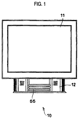
FIGS. 1A and 1B are a plan view and side view, respectively, of an operation panel section provided with a first embodiment of a switch structure of the present invention;
FIG. 2 is an exploded perspective view showing component parts of the operation panel section;
FIG. 3 is a perspective view of a panel member as viewed from the underside thereof;
FIG. 4 is a side sectional view of the operation panel section taken along the C-C line of FIG. 1A;
FIG. 5 is a sectional side view of the operation panel section taken along the A-A line of FIG. 1A;
FIG. 6 is a sectional side view of the operation panel section taken along the I-I line of FIG. 1A;
FIG. 7 is a sectional side view showing a detailed construction of the first embodiment switch structure;
FIG. 8 is an exploded perspective view showing a casing and component parts around the casing of an electronic keyboard instrument provided with the switch structure;
FIG. 9 is a sectional side view showing a detailed construction of a second embodiment of the switch structure;
FIG. 10 is a sectional side view showing a detailed construction of a third embodiment of the switch structure;
FIG. 11 is a sectional side view showing a detailed construction of a fourth embodiment of the switch structure; and
FIG. 12 is a sectional side view showing an operation panel section employing a combination of the first to third embodiments of the switch structure of the present invention.
Detailed description
[First Embodiment]
FIGS. 1A and 1B are plan and side views, respectively, of an operation panel section 1 provided with a first embodiment of a switch structure (or electronic component part installing mechanism) 10 of the present invention. FIG. 2 is an exploded perspective view showing component parts of the operation panel section 1, and FIG. 3 is a perspective view of a panel member 20 as viewed from the underside 20b thereof. Further, FIGS. 4 to 6 are side sectional views of the switch structure 10, of which FIG. 4 is a sectional side view taken along the C-C line of FIG. 1A, FIG. 5 is a sectional side view taken along the A-A line of FIG. 1A and FIG. 6 is a sectional side view taken along the I-I line of FIG. 1A. Furthermore, FIG. 7 is a sectional side view showing a detailed construction of the switch structure 10, and FIG. 8 is an exploded perspective view showing a casing 2 and component parts around the casing 2 of a desktop-type electronic keyboard instrument 100 including the operation panel section 1 provided with the first embodiment of the switch structure 10.
As shown in FIG. 8, the first embodiment of the switch structure 10 is applied to the operation panel section 1 having various controls (or operators) of the electronic keyboard instrument 100 arranged thereon and operable by a user to perform various operation. The casing 2 shown in the figure is provided on and covers the upper surface side of a body section (not shown) of the electronic keyboard instrument 100, and a middle opening portion 3 of a generally rectangular shape for mounting therein a keyboard (not shown) is formed in a front central region of an upper wall 2a of the casing 2. A pair of side opening portions 4 each having a generally circular shape are formed on opposite sides of the middle opening portion 3 for mounting therein speakers 5. Note that only one of the side opening portions 4 is shown in the figure. The operation panel section 1 includes a panel member 20 of a flat plate shape constituted by a part of the upper wall 2a of the casing 2, and an intermediate member 40 and circuit board 60 adjacent to the lower surface 20b (FIG. 1) of the panel member 20. As shown in FIGS. 1 and 2, the first embodiment of the switch structure 10 is a structure which includes the panel member 20 and the intermediate member 40 disposed in superposed relation to each other with the intermediate member 40 sandwiched therebetween.
Note that the terms "upper", "lower", "upper surface", "lower surface", etc. are used herein to refer to directions as viewed when the panel member 20, intermediate member 40 and circuit board 60 are disposed in a horizontal orientation and in vertically superposed relation to one another, and these terms are defined regardless of actual installed or mounted positions of the operation panel section 1 and switch structure 10. Further, the operation panel section 1 is not necessarily installed with the panel member 20 oriented horizontally, it may sometimes be installed with the panel member 20 oriented vertically, depending on a form of its installation to electronic equipment, such as the electronic keyboard instrument 100.
As shown in FIG. 2, the circuit board 60 is a circuit board formed of a hard material in a substantially rectangular flat plate shape, and a plurality of switch sections (electronic component part installing sections) 62 having their respective fixed contacts 61a formed thereon are provided on the upper surface 60a of the circuit board 60 at predetermined intervals along a longitudinal direction of the upper surface 60a. Further, light emitting elements 65, such as LEDs, are mounted on predetermined positions of the upper surface 60a of the circuit board 60. It should be noted that, through a whole of the present disclosure, the term of "electronic component part" represents a broad technical concept including not only an element of electronic/electric circuits or devices but also a switch or switch element (namely, a contact). Also, the term of "electronic/electric component part" has the same meaning as the term of "electronic component part" as described above.
The intermediate member 40 is a one-piece member formed integrally of a resilient, flexible material, such as silicon, rubber or synthetic resin, and it has a thin overall shape elongated along the longitudinal direction of the circuit board 60. Further, as shown in FIG. 4, the intermediate member 40 includes: a base section 45 having fixing portions 41 each disposed around the outer periphery of one of the switch sections 62 on the upper surface 60a of the circuit board 60, and cylindrical held portions 43 each formed integrally with an upper end portion of a corresponding one of the fixing portions 41; operator portions 47 each provided for driving a corresponding one of the switch sections 62; and connection portions 49 each resiliently (movably) connecting a corresponding one of the operator portions 47 to the base section 45.
Each of the fixing portions 41 is provided with its lower surface 41b held in contact with the upper surface 60a of the circuit board 60 and surrounds a corresponding one of the switch sections 62. Each of the held portions 43 is formed integrally with the upper end of the corresponding fixing portion 41 and disposed around the corresponding switch section 62, and each of the held portions 43 is in the form of a cylindrical projection extending upwardly from the upper end of the corresponding fixing portion 41. Note that a boundary portion between the upper surface 41a of each of the fixing portion 41 and the corresponding held portion 43 (i.e., lower end corner region of the outer peripheral surface of the held portion 43) is formed as a portion against which is abutted the lower end 25b of a later-described holding portion 25 of the panel member 20.
Each of the operator portions (operators) 47 is in the form of a substantially circular cylinder with its axis extending vertically, and it projects upwardly in such a manner that its upper surface 47a is located above an upper end portion 43a of a corresponding one of the held portions 43. Further, the outer periphery of the lower surface 47b of each of the operator portions 47 is connected to the inner periphery of a corresponding one of the fixing portions 41 via the connection portion 49 of a thin plate shape. In this manner, each of the operator portions 47 is supported with its lower surface 47b located slightly above (spaced upwardly from) the lower surface 41b of the fixing portion 41. Further, a movable contact 61b constituting a switch contact (electronic component part) 61 is provided on the lower surface 41b of each of the operator portions 47.
A plurality of the switch structures 10, each comprising a set of the above-mentioned base section 45 (fixing portion 41 and held portion 43), operator portion 47 and connection portion 49, are provided at predetermined intervals along the longitudinal direction of the intermediate member 40. The fixing portions 41 of every two adjoining switch structures 10 are interconnected via a connecting portion 51. Each of the connecting portions 51 is a thin plate-shaped portion spanning between two adjoining fixing portions 41, and it is fixed to the fixing portions 41 with its lower surface 41b located slightly above (spaced upwardly from) the lower surfaces 41b of the fixing portions 41. Thus, with the fixing portions 41 mounted or installed on the upper surface 60a of the circuit board 60, as shown in FIGS. 4 and 7, a slight gap A is formed or defined between the lower surface 51b of each of the connecting portions 51 and the upper surface 60a of the circuit board 60.
As shown in FIGS. 1 to 3, the panel member 20 is a flat plat-shaped member having a horizontally-elongated overall shape. The panel member 20 includes a flat plate-shaped body portion 21, a plurality of opening portions 23 formed in the body portion 21, and cylindrical holding portions 25 each formed on the lower surface 20b along the outer periphery of a corresponding one of the opening portions 23 and projecting downward, i.e. toward the circuit board 60. Each of the opening portions 23 is in the form of a through-hole of a circular cross-sectional shape having a diameter slightly larger than the outer diameter of the operator portion 47, and, as shown in FIG. 4, the operator portion 47 is passed through the opening portion 23 in such a manner that its upper surface 47a is exposed on the upper surface 20a of the panel member 20. Namely, the opening portions 23 are formed in positions corresponding to the operator portions 47 of the intermediate member 40, and each of the holding portions 25 is a cylindrical projection provided around a corresponding one of the opening portions 23 and has an inner diameter substantially equal to the outer diameter of a corresponding one of the held portions 43 in such a manner that the held portions 43 of the intermediate member 40 can be fitted inside, i.e. fittedly held in, the holding portion 25. Further, the holding portion 25 is sized such that, with the panel member 20 and the circuit board 60 fixed together by means of later-described screws (fixing means) 70, its lower end 25b is pressed against the upper surface 41a of the fixing portion 41 of the intermediate member 40. Note that, for convenience of die molding, various projecting component parts, such as the aforementioned holding portion 25, held portion 43 and operator portion 47, are shaped to taper from their proximal end toward their distal end. With such tapering shapes, fitting engagement between the holding portion 25 and the held portion 43 etc. can be effected smoothly.
Further, as shown in FIGS. 2 and 3, mounting bosses 27 each in the form of a projection of a circular columnar shape are formed on the lower surface 20b of the panel member 20 at predetermined positions near the outer periphery of the lower surface 20b. Further, a screw hole 28 for screwing engagement with the screw 70 is formed in a distal end portion of each of the bosses 27, and screw holes 67 each for passage therethrough of a screw are formed in the circuit board 60 at a plurality of positions near the outer periphery of the circuit board 60. Further, the bosses 27 of the panel member 20 and the screw holes 67 of the circuit board 60 are formed in mutually-corresponding positions. The screws (fixing means) 70 are provided for fastening or fixing together the panel member 20 and the circuit board 60 in face-to-face pressed engagement. The screws 70 are each passed through the screw hole 67 from the side of the lower surface 60b of the circuit board 60 and fixedly screwed into the hole 28 of the boss 27.
Furthermore, small holes 22 are formed in the body portion 21 of the panel member 20 at positions corresponding to the light emitting elements 65 in such a manner that the light emitting elements 65 are exposed out of the small holes 22. Furthermore, another circuit board 80 is provided adjacent to the lower surface 20b of the panel member 20, and an electronic component part 82 that is a rotary variable resistor is mounted on the circuit board 80. A through-hole 24 for passage therethrough of a rotation shaft 82a of the electronic component 82 is formed in the body portion 21 of the panel member 20 at a position corresponding to the electronic component 82. In addition, as a structure for fixing the circuit board 80 to the lower surface 20b of the panel member 20, the operation panel 1 further includes a boss 29 provided on the lower surface 20b and having a screw hole 30 formed in the boss 29, and a screw hole 87 formed through the circuit board 80 for passage therethrough of a screw, and a screw 71 screwed into the screw hole 30.
As shown in FIGS. 1B and 8, the upper surface 20a of the panel member 20 is located slightly lower than the upper surface of the upper wall 2a. Although not particularly shown, a sheet member of a thin plate shape can be mounted over the upper surface 20a of the panel member 20. In such a case, openings are formed in the sheet member at positions which correspond to the opening portions 23 through which the upper surfaces 47a of the operator portion 47 project.
According to the instant embodiment of the switch structure 10, where the panel member 20 and the circuit board 60 are fixed together in face-to-face pressed engagement with each other with the intermediate member 40 sandwiched therebetween, each of the operator portions 47 of the intermediate member 40 is inserted in a corresponding one of the opening portions 23 of the panel member 20 in such a manner that the upper surface 47a of the operator portion 47 is exposed out of the opening portion 23 toward the upper surface 20a of the panel member 20. Further, the held portion 43 of the intermediate member 40 is fittedly held inside the holding portion 25 of the panel member 20. Further, the upper surface 41a of the fixing portion 41 of the intermediate member 40, more particularly the boundary portion between the upper surface 41a of the fixing portion 41 and the held portion 43, is sandwiched between the lower end 25b of the holding portion 25 of the panel member 20 and the upper surface 60a of the circuit board 60. Further, in this state, the connecting portion 51 interconnecting the adjoining fixing portions 41 is disposed with the gap A defined between the connecting portion 51 and the upper surface 60a of the circuit board 60.
The description continues in the full USPTO document.
 Lapsed, fee not paid6 drawings

