Cross-reference to related applications
The present application claims the benefit of priority from Japanese Patent Application No. 2010-236814 filed in Japan on Oct. 21, 2010, the entire contents of which are incorporated herein by reference.
Background of the invention
1. Field of the invention
The present invention relates to a case for a portable image reading apparatus.
2. Description of the related art
Image reading apparatuses include a portable image reading apparatus that is designed to be carried everywhere by a user. The portable image reading apparatus is generally carried in a bag. When the portable image reading apparatus is carried in a bag without any protections, the portable image reading apparatus may get dirty and scratches, or be damaged. In order to prevent the portable image reading apparatus from deteriorating, a dedicated case for housing a portable image reading apparatus (hereinafter, simply referred to as a "carry case") may be used. Refer to U.S. Patent Application Publication No. 2005/0094216. The carry case is mainly used when the portable image reading apparatus is not in use for the purpose mentioned above. Furthermore, another portable image reading apparatus is disclosed that is integrated with a carry case. Refer to Japanese Patent No. 3258448.
When a portable image reading apparatus housed in a related art carry case is used, the portable image reading apparatus is taken from the carry case and placed on a desk, for example, so as to be ready to be used. Meanwhile, the carry case is put in another place for clearing. When a user uses the portable image reading apparatus in a train, a bus, or a waiting room in a station or an airport, for example, an available area for the portable image reading apparatus is limited and the user needs to use the portable image reading apparatus on an existing small desk or on the user's laps, for example. In such a situation, it may be difficult to take out the portable image reading apparatus from the carry case or put the case in another palace for clearing. Furthermore, such handling may seem troublesome for the user. In some portable image reading apparatuses, trays are not provided that would be used for conveying read media from which images are read. Particularly, discharge trays are not provided in some cases on which the read media ejected from the portable image reading apparatuses after being read would be placed. With such portable image reading apparatuses, a read medium conveyed from the portable image reading apparatus is ejected in the place where the portable image reading apparatus is placed. Depending on the conditions of the place in which the read medium is ejected, the read medium may not be stably ejected. For example, if obstacles are present in the place where the read medium is ejected, or an area where the read medium is ejected has a shape that is likely to catch the read medium, the read medium is not stably ejected. In such cases, images read by the portable image reading apparatus may be distorted or the read media may be damaged.
There is a need for a case for a portable image reading apparatus that can achieve at least one of a stable use and an easy use of the portable image reading apparatus, regardless of the conditions of a place where the portable image reading apparatus is used.
Summary of the invention
It is an object of the present invention to at least partially solve the problems in the conventional technology.
According to one aspect of the invention, the invention is directed to a case for a portable image reading apparatus. The case includes a body for housing the portable image reading apparatus that, while conveying a read medium as an image reading object, reads the image from the read medium; a cover supported with respect to the body to be rotatable around a longitudinal direction of the body; and a lock unit for locking the cover with respect to the body in a closing state in which the cover covers the body when the cover is rotated with respect to the body in an approaching direction in which the cover approaches the body. When the cover is rotated with respect to the body in a withdrawing direction opposite to the approaching direction, with the lock by the lock unit released, the cover is developed to form a discharge path of the read medium.
The above and other objects, features, advantages and technical and industrial significance of this invention will be better understood by reading the following detailed description of presently preferred embodiments of the invention, when considered in connection with the accompanying drawings.
Brief description of the drawings
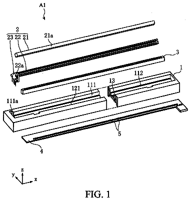
FIG. 1 is an external view of a case for a portable image reading apparatus according to a first embodiment.
FIG. 2 is a plan view of the case for a portable image reading apparatus according to the first embodiment.
FIG. 3 is a schematic illustrating a state in which a portable image reading apparatus is housed in the case.
FIG. 4 is a cross-sectional view of the case for a portable image reading apparatus.
FIG. 5 is a schematic illustrating an example of an overall structure of a carry case according to a modification example 2.
FIG. 6 is a schematic illustrating an example of an overall structure of a carry case according to a modification example 3.
FIG. 7 is a schematic illustrating an example of an overall structure of a carry case according to a modification example 4.
FIG. 8 is an external view of a case for a portable image reading apparatus according to a second embodiment.
FIG. 9 is a schematic illustrating a state in which a portable image reading apparatus is housed in the case.
FIG. 10 is a plan view of a case for a portable image reading apparatus according to a third embodiment.
Detailed description of the preferred embodiments
The present invention is described below in detail with reference to the accompanying drawings. The present invention, however, is not limited to the following embodiments. The elements of the following embodiments include elements that those skilled in the art can easily assume or that are substantially the same as the elements known by those in the art. In the following embodiments, an image scanner that a user can carry with him is described as an example of a portable image reading apparatus. The present invention, however, is not limited to the image scanner. The present invention can be applied to any portable apparatus that scans a read medium as an image reading object with an image sensor, such as a copying machine, a facsimile, and a character recognition apparatus, and a user can carry with him.
First Embodiment
FIG. 1 is an external view of a case for a portable image reading apparatus according to a first embodiment. FIG. 2 is a plan view of the case for a portable image reading apparatus according to the first embodiment. FIG. 3 is a schematic illustrating a state in which a portable image reading apparatus is housed in the case. FIG. 4 is a cross-sectional view of the case for a portable image reading apparatus. FIG. 4 is the cross-sectional view in a plane orthogonal to a sub-scanning direction of the case for a portable image reading apparatus in which the portable image reading apparatus is housed.
As illustrated in FIG. 1, a case 1-1 for a portable image reading apparatus (hereinafter simply referred to as a "carry case") houses an image scanner 100. In the image scanner 100, a medium to be read (also simply referred to as a read medium) is inserted manually by a user from an insertion port 101, and conveyed by a conveying unit (not illustrated) to an imaging unit having an image sensor (not illustrated). The image scanner 100 reads the read medium that is being conveyed by the imaging unit to produce read image data of the read medium, and discharges the read medium after being read from an outlet 102 by the conveying unit. A connector 103 is used for electrically connecting the image scanner 100 to external equipment such as a personal computer and a mobile terminal. The connector 103 is electrically connected to a connector of external equipment with a connecting cable such as an interface cable. This electrical connection allows the image scanner 100 to output produced read image data to an external terminal, to receive electric power to operate the image scanner 100, and to change operation setting for reading a read medium by input from an external terminal.
As illustrated in FIGS. 1 to 4, the carry case 1-1 includes a body 2, a cover 3, and a lock unit 4.
The body 2 houses the image scanner 100. The body 2 includes a housing member 21, a bottom member 22, and a partition 23. The housing member 21 is made of a synthetic resin such as an acrylonitride-butadiene-styrene (ABS) resin, for example. The housing member 21 includes a bottom surface member 21a, side surface members 21b and 21c, a front rib 21d, and rear ribs 21e and 21f.
The bottom surface member 21a, on which the image scanner 100 is placed when the image scanner 100 is housed in the body 2, is formed in a rectangular shape. The side surface members 21b and 21c are formed at both edges of the bottom surface member 21a in a longitudinal direction of the body 2, i.e., in a width direction of the carry case 1-1. The bottom surface member 21a is formed such that the length between the side surface members 21b and 21c in the longitudinal direction, i.e., the length of a first housing unit S1 in the longitudinal direction, is equal or nearly equal to the width of the image scanner 100. Therefore, the side surface members 21b and 21c function as a limiting mechanism that limits a state of the image scanner 100 housed in the body 2, i.e., movement of the image scanner 100 in the housed state in the longitudinal direction relative to the body 2. This mechanism can limit the movement of the image scanner 100 relative to the carry case 1-1 (movement in the longitudinal direction) when the image scanner 100 in the housed state reads a read medium, so that the image scanner 100 can more stably read a read medium while being housed. The bottom surface member 21a has a notch 21g. The bottom surface member 21a has both edges in a front-back direction. The notch 21g is formed from an edge on a back side toward a front side. The front-back direction is orthogonal to the longitudinal direction and an up-down direction of the body 2. The direction toward the front rib 21d side is defined as the front side, while the direction toward the rear ribs 21e and 21f sides is defined as the back side. The notch 21g is formed in an area surrounded by the rear ribs 21e and 21f, and the ribs 21h and 21i (which are described later).
The side surface members 21b and 21c are formed such that the distance in the up-down direction from the bottom surface member 21a, i.e., the distance of the first housing unit S1, which is described later, in the up-down direction is larger than the height of the image scanner 100. The up-down direction is orthogonal to the longitudinal direction and the front-back direction of the body 2. The direction toward the bottom surface member 21a side is defined as the down direction, while the direction toward a side opposite the bottom surface member 21a side is defined as the up side. The side surface member 21b has the rib 21h on an inner wall surface thereof, while the side surface member 21c has the rib 21i on an inner wall surface thereof. The ribs 21h and 21i protrude from the respective inner wall surfaces opposite to each other in the longitudinal direction so as to face each other. The ribs 21h and 21i are formed such that distances between the front rib 21d and the ribs 21h and 21i in the front-back direction, i.e., the length of the first housing unit S1 in the front-back direction, is equal or nearly equal to the length orthogonal to the depth of the image scanner 100. Therefore, the side surface members 21b and 21c, and the front rib 21d function as a limiting mechanism that limits the movement of the image scanner 100 in the housed state in the front-back direction relative to the body 2. When the image scanner 100 in the housed state reads a read medium, this mechanism can limit the movement of the image scanner 100 relative to the carry case 1-1 (movement in the front-back direction). Accordingly, the image scanner 100 in a housed state can more stably read a read medium.
The side surface member 21b has a connecting hole 21j at a location facing the connector 103 of the image scanner 100 in the housed state. The connecting hole 21j penetrates the side surface member 21b in the longitudinal direction. The connecting hole 21j is formed in such a shape that a connecting cable to be connected to the connector 103 of the image scanner 100 can be inserted, for example. Therefore, a connecting cable can be connected to the connector 103 of the image scanner 100 while the image scanner 100 is being housed in the body 2. Because of this, the image scanner 100 can be electrically connected to external equipment without being removed from the body 2, and then can read a read medium, produce read image data, and output the data to external equipment. Furthermore, read image data stored in a storage unit included in the image scanner 100 can be output to external equipment while the image scanner 100 is being housed in the body 2. The connecting hole 21j is not limited to be formed on the side surface member 21b, but can be formed at any location on the body 2 because the connecting hole 21j is formed corresponding to the location of the connector 103 of the image scanner 100 in the housed state. When the carry case 1-1 is used for the image scanners 100 of different types having the connectors 103 at different locations, a plurality of connecting holes 21j may be formed corresponding to the respective locations of the connectors 103 of the image scanners 100.
The connecting hole 21j is plugged by inserting a cap 5 into the connecting hole 21j. The cap 5 is made by material having elasticity such as a synthetic resin or rubber, for example. The cap 5 is composed of a plug 5a and a support 5b. The plug 5a, inserted into the connecting hole 21j, plugs the connecting hole 21j. The plug 5a is formed so as to be attachable to and detachable from the connecting hole 21j. When the image scanner 100 in the housed state is not electrically connected to external equipment, the connector 103 can be prevented from being exposed out of the carry case 1-1 by plugging the connecting hole 21j with the cap 5. As a result, entry of dust and dirt from an outside into an inside of the body 2 and deposition of dust and dirt on the connector 103 can be prevented. The support 5b is supported by the body 2 and is formed so as to protrude backward from the edge on the back side of the plug 5a. The support 5b is inserted into a supporting hole (not illustrated) of the side surface member 21b so as to be supported by the body 2. Therefore, the support 5b can prevent the cap 5, removed from the connecting hole 21j, from being separated from the body 2. As a result, the cap 5 can be prevented from being lost.
The front rib 21d, U-shaped when viewed from the front side, is formed at the edge on the front side of the bottom surface member 21a. Both edges in the longitudinal direction of the front rib 21d are integrally formed with the side surface members 21b and 21c, respectively. The front rib 21d, when viewed from the front side, is formed so as not to overlap with the insertion port 101 of the image scanner 100 in the housed state. Accordingly, while the image scanner 100 is being housed in the body 2, this structure can prevent the front rib 21d from hindering a user who is manually inserts a read medium into the insertion port 101.
The rear ribs 21e and 21f are integrally formed with the side surface members 21b and 21c, respectively, at the edge on the back side and also at both ends in the longitudinal direction of the bottom surface member 21a. The rear ribs 21e and 21f, when viewed from the back side, are formed so as not to overlap with the outlet 102 of the image scanner 100 in the housed state. Accordingly, while the image scanner 100 is being housed in the body 2, the rear ribs 21e and 21f can be prevented from coming into contact with a read medium ejected from the outlet 102 by the conveying unit. As a result, this arrangement can prevent the rear ribs 21e and 21f from hindering a read medium ejected by the conveying unit.
The bottom surface member 21a of the housing member 21 is fixed on the bottom member 22. The bottom member 22 is provided with the partition 23. The bottom member 22 is formed in a rectangular shape with the following structure, for example. A core such as a paper board is layered on a resin sheet such as a polyvinyl chloride (PVC) sheet. Then, part at which the core is exposed is covered with a top sheet such as cloth to form the structure in which the core is sandwiched between the top sheet and the resin sheet. In the embodiment, with regard to the bottom member 22a, a back surface 22a thereof, which is fixed to the housing member 21, is formed from a PVC sheet. A front surface 22b opposite the back surface 22a of the bottom member 22 is formed from cloth. The bottom member 22 is formed longer than the housing member 21 in the front-back direction. When fixed to the housing member 21, the bottom member 22 forms a protrusion 22c protruding forward from the housing member 21.
The partition 23, for example, is formed in a rectangular shape, with a core such as a paper board covered by a resin sheet such as a PVC sheet. The partition 23 is formed shorter than the notch 21g in the longitudinal direction. The partition 23 is disposed at the notch 21g and is supported rotatably around the longitudinal direction with respect to the bottom member 22 at a rotation reference A. In the embodiment, when the partition 23 stands in the up-down direction, i.e., is in a standing state (refer to FIG. 4), the rotation reference A is set between an edge 23b on the back side and the back surface 22a facing the edge 23b. The edge 23c is the edge on the back side out of both edges in the front-back direction of a bottom surface 23a facing the bottom member 22. That is, the partition 23 is supported rotatably around the longitudinal direction with respect to the body 2. Specifically, while the partition 23 is being stood, a rear surface 23c on the back side of the partition 23 and the back surface 22a of the bottom member 22 are linked with a transformable sheet (e.g., a resin sheet), or the rear surface 23c and the back surface 22a are formed in a single resin sheet, so that the partition 23 is supported rotatably around the longitudinal direction with respect to the bottom member 22. The partition 23 is formed so as not to protrude above the side surface members 21b and 21c when the partition 23 is in the standing state. When the partition 23 is stood, the body 2 is partitioned into two spaces. One space is formed between the partition 23 and the front rib 21d: the first housing unit S1 housing the image scanner 100. The other space is formed between the partition 23 and the rear ribs 21e and 21f: a second housing unit S2. Providing the partition 23 allows the body 2 to house the image scanner 100 in the first housing unit S1 and to house in the second housing unit S2 peripherals of the image scanner 100 such as the connecting cable described above. Consequently, when the image scanner 100 is housed in the carry case 1-1 and is carried around, a case can be prevented in which peripherals that are not housed in the carry case 1-1 are put in a bag as separate luggage, because peripherals, such as the connecting cable, of the image scanner 100 can be housed in the carry case 1-1 as described above.
The cover 3 covers the body 2 to cover the image scanner 100 housed in the body 2. The cover 3 is composed of a plurality of panel members: panel members 31, 32, and 33. The panel members 31, 32, and 33 are formed such that their lengths are equal or nearly equal to that of the body 2 in the longitudinal direction. The panel members 31, 32, and 33 are formed in the same manner as the bottom member 22. For example, each of the panel members 31, 32, and 33 is formed in a rectangular shape with the following structure. A core such as a paper board is layered on a resin sheet such as a PVC sheet. Then, part at which the core is exposed is covered with a top sheet such as cloth to form the structure in which the core is sandwiched between the top sheet and the resin sheet. In the embodiment, back surfaces 31a, 32a, and 33a of the panel members 31, 32, and 33 facing the body 2 are formed from a PVC sheet, and on the opposite side, front surfaces 31b, 32b, and 33b are formed from cloth.
The panel member 31 faces the rear ribs 21e and 21f of the body 2 when the cover 3 covers the body 2, i.e., in a closed state. The panel member 31 is supported rotatably around the longitudinal direction with respect to the bottom member 22 at a rotation reference B. In the embodiment, the rotation reference B is set between an edge 31c and an edge 22k. The edge 31c is the edge on the bottom member 22 side out of both edges in a sideways direction of the back surface 31a of the panel member 31. The edge 22k is the edge on the back side of the back surface 22a facing the edge 31c. That is, the panel member 31 is supported rotatably around the longitudinal direction with respect to the body 2. The sideways direction is orthogonal to the longitudinal direction and the thickness direction of each of the panel members 31, 32, and 33 (the front-back direction in FIG. 1).
The panel member 32, in the closed state, faces the edges on the up side of the side surface members 21b and 21c of the body 2. The panel member 32 is supported rotatably around the longitudinal direction with respect to the panel member 31 at a rotation reference C. In the embodiment, the rotation reference C is set between an edge 32c and an edge 31d. The edge 32c is the edge on the panel member 31 side out of both edges in the sideways direction of the back surface 32a of the panel member 32. The edge 31d is the edge on the panel member 32 side out of both edges in the sideways direction of the back surface 31a facing the edge 32c. That is, the panel member 32 is supported rotatably around the longitudinal direction with respect to the body 2 with the panel member 31 interposed therebetween.
The panel member 33, in the closed state, faces the front rib 21d of the body 2. The panel member 33 is supported rotatably around the longitudinal direction with respect to the panel member 32 at a rotation reference D. In the embodiment, the rotation reference D is set between an edge 33c and an edge 32d. The edge 33c is the edge on the panel member 32 side out of both edges in the sideways direction of the back surface 33a of the panel member 33. The edge 32d is the edge on the panel member 33 side out of both edges in the sideways direction of the back surface 32a which faces the edge 33c. That is, the panel member 33 is supported rotatably around the longitudinal direction with respect to the body 2 with the panel members 31 and 32 interposed therebetween. In this way, since the panel members 31, 32, and 33 are supported such that they can rotate around the longitudinal direction at the respective rotation references B, C, and D, the cover 3 is supported rotatably around the longitudinal direction with respect to the body 2.
The lock unit 4 locks the cover 3 to the body 2. The lock unit 4 includes a plurality of panel members 41 and 42, a first lock member 43, a second lock member 44, and a weight 45. The panel members 41 and 42 are formed such that their lengths in the longitudinal direction are nearly one half to one third of that of the body 2. The panel members 41 and 42 are formed in the same manner as the bottom member 22. For example, each of the panel members 41 and 42 is formed in a rectangular shape with the following structure. A core such as a paper board is layered on a resin sheet such as a PVC sheet. Then, part at which the core is exposed is covered with a top sheet such as cloth to form the structure in which the core is sandwiched between the top sheet and the resin sheet. In the embodiment, back surfaces 41a and 42a of the panel members 41 and 42 facing the body 2 are formed from a PVC sheet, and on the opposite side, front surfaces 41b and 42b are formed from cloth.
The panel member 41, after the closed state, faces the front rib 21d of the body 2 with the panel member 33 interposed therebetween, when locking the cover 3 to the body 2, i.e., in a locking state. The panel member 41 is supported rotatably around the longitudinal direction with respect to the bottom member 22 at a rotation reference E. In the embodiment, the rotation reference E is set between an edge 41c and an edge 22m. The edge 41c is the edge on the bottom member 22 side out of both edges in a sideways direction of the back surface 41a of the panel member 41. The edge 22m is the edge on the back side of the back surface 22a which faces the edge 41c. That is, the panel member 41 is supported rotatably around the longitudinal direction with respect to the body 2. The sideways direction is orthogonal to the longitudinal direction and the thickness direction of each of the panel members 41 and 42 (the front-back direction in FIG. 1).
The panel member 42, in the locking state, faces the edges on the up side of the side surface members 21b and 21c of the body 2 with the panel member 32 interposed therebetween. The panel member 42 is supported rotatably around the longitudinal direction with respect to the panel member 41 at a rotation reference F. In the embodiment, the rotation reference F is between an edge 42c and an edge 41d. The edge 42c is the edge on the panel member 41 side out of both edges in the sideways direction of the back surface 42a of the panel member 42. The edge 41d is the edge on the panel member 42 out of both edges in the sideways direction of the back surface 41a which faces the edge 42c. That is, the panel member 42 is supported rotatably around the longitudinal direction with respect to the body 2 with the panel member 41 interposed therebetween. In this way, since the panel members 41 and 42 are supported such that they can rotate around the longitudinal direction at the respective rotation references E and F, the lock unit 4 is supported rotatably around the longitudinal direction with respect to the body 2.
The first lock member 43 and the second lock member 44 are used to lock the cover 3 to the body 2. In the embodiment, the first lock member 43 and the second lock member 44 form a hook-and-loop fastener. The structure formed by the first lock member 43 and the second lock member 44 is not limited to the hook-and-loop fastener. A combination of a magnet and a magnetic body, or a combination of a hook-shaped member and a member receiving the hook-shaped member may be acceptable, for example. The first lock member 43 is disposed on the back surface 42a of the panel member 42. The second lock member 44, in the locking state, is disposed on the front surface 32b of the panel member 32 at a location at which the second lock member 44 faces the first lock member 43.
The weight 45 is attached on the panel member 42 so as to cover an edge 42d on a side opposite to the panel member 41 side out of both edges in the sideways direction of the panel member 42, and so as to cover a part of the back surface 42a and the front surface 42b.
How the image scanner 100 is housed in the carry case 1-1 according to the first embodiment is described below. First, the image scanner 100 is housed in the body 2. Herein, a user places the image scanner 100 into the first housing unit S1 of the body 2. The image scanner 100 in the housed state is conveyed backward, and a read medium is also ejected backward. When a peripheral 200 is housed in the body 2 together with the image scanner 100, a user sets the partition 23 in the standing state and thereafter places the peripheral 200 in the second housing unit S2. In this way, the image scanner 100 and the peripheral 200 are housed in the body 2.
Then, while the image scanner 100 and the peripheral 200 are housed in the body 2, the cover 3 is rotated in an approaching direction in which the cover 3 approaches the body 2. The cover 3 covers the body 2 to be set in the closed state. Specifically, the user rotates the panel member 31 of the cover 3 at the rotation reference B in the approaching direction with respect to the bottom member 22, so that the panel member 31 faces the rear ribs 21e and 21f of the body 2. Then, the user rotates the panel member 32 at the rotation reference C in the approaching direction with respect to the panel member 31 facing the rear ribs 21e and 21f of the body 2. As a result, the panel member 32 faces the edges on the up side of the side surface members 21b and 21c of the body 2. Then, the user rotates the panel member 33 at the rotation reference D in the approaching direction with respect to the panel member 32 facing the edges on the up side of the side surface members 21b and 21c of the body 2. Consequently, the panel member 33 faces the front rib 21d of the body 2. After the rotation, an edge 33d faces the protrusion 22c of the bottom member 22 in the up-down direction. The edge 33d is the edge on the side opposite to the panel member 32 side out of both edges in the sideways direction of the back surface 33a.
Thereafter, while the cover 3 is in the closed state, the cover 3 is locked to the body 2 by the lock unit 4. Specifically, the user rotates the panel member 41 of the lock unit 4 at the rotation reference E in the approaching direction with respect to the bottom member 22, so that the panel member 41 faces the panel member 33 in the closed state. Then, the user rotates the panel member 42 at the rotation reference F in the approaching direction with respect to the panel member 41 facing the panel member 33 in the closed state. As a result, the panel member 42 faces the panel member 32. Then, the user brings the first lock member 43 into contact with the second lock member 44 to lock the cover 3 to the body 2. Accordingly, the image scanner 100 and the peripheral 200 are housed in the carry case 1-1.
A case is described below in which the image scanner 100 housed in the carry case 1-1 is used, according to the first embodiment. First, a user places the carry case 1-1 housing the image scanner 100 and the peripheral 200 at a place where the image scanner 100 and the peripheral 200 are used. Then, the lock held by the lock unit 4 is released. Specifically, the user releases the contact between the first lock member 43 and the second lock member 44. Then, the user rotates the panel member 42 with respect to the panel member 41 at the rotation reference F in a withdrawing direction opposite to the approaching direction, and rotates the panel member 41 at the rotation reference E in the withdrawing direction with respect to the bottom members 22, so that the panel members 41 and 42 are developed to be in a developed state. The weight 45 attached on the panel member 42 can prevent the panel members 41 and 42 in the developed state from being rotated again in the approaching direction. Accordingly, the panel members 41 and 42, when viewed from the front side, can be prevented from overlapping with the insertion port 101 of the image scanner 100 in the housed state. While the image scanner 100 is being housed in the body 2, when a user manually inserts a read medium into the insertion port 101, this developed state can prevent the panel members 41 and 42 from hindering the insertion.
Then, while the lock held by the lock unit 4 is released, the user rotates the cover 3 in the withdrawing direction from the body 2, so that the cover 3 is developed. Specifically, the user rotates the panel member 33 at the rotation reference D in the withdrawing direction with respect to the panel member 32, and then rotates the panel member 32 at the rotation reference C in the withdrawing direction with respect to the panel member 31, and further rotates the panel member 31 at the rotation reference B in the withdrawing direction with respect to the bottom member 22. Consequently, the cover 3 is developed.
The user takes out the peripheral 200 from the body 2 and sets the partition 23 to a slanted state from the standing state. Specifically, the user rotates the partition 23 in the standing state at the rotation reference A in the withdrawing direction with respect to the bottom member 22, by which the partition 23 is in the slanted state. As a result, the partition 23 can be prevented from coming into contact with a read medium ejected from the outlet 102, and the read medium can be stably ejected.
The image scanner 100 in the housed state reads a read medium. Specifically, the user inserts a connecting cable included in the peripheral 200 into the connecting hole 21j from which the cap 5 has been removed, and electrically connects the connecting cable to the connector 103 of the image scanner 100. The user electrically connects the connecting cable to external equipment to supply electric power to the image scanner 100. Then, the user sets the image scanner 100 to a readable state, and thereafter manually inserts a read medium into the insertion port 101, so that the image scanner 100 starts reading the read medium. The read medium after being read out is ejected from the outlet 102. In the ejection, since the ejection takes place backward, the read medium ejected is further ejected along the cover 3 in the developed state. In other words, in the embodiment, the cover 3 forms a discharge path for discharging a read medium.
As described above, the carry case 1-1 according to the embodiment, which houses the image scanner 100 in the body 2, allows the image scanner 100 to read a read medium. Accordingly, procedures taking out the image scanner 100 from the carry case 1-1, and clearing the carry case 1-1 after the image scanner 100 is taken out are saved. As a result, the image scanner 100 can be easily used. Furthermore, since the cover 3 in the developed state forms a discharge path by covering a place where the image scanner 100 is used, a read medium ejected from the image scanner 100 is always ejected along the cover 3 in the developed state regardless of the place where the image scanner 100 is used. The cover 3 in the developed state allows a read medium to be stably ejected without any influence on the place where the image scanner 100 is used. As a result, the image scanner 100 can be stably used.
Modification Example 1
In the first embodiment, a partition rotation mechanism that applies a force rotating the partition 23 in the withdrawing direction with respect to the body 2 may be included. In the embodiment, the partition rotating mechanism rotates the partition 23 at the rotation reference A in the withdrawing direction with respect to the bottom member 22. In the first embodiment, a cover rotation mechanism that applies a force rotating the cover 3 in the withdrawing direction with respect to the body 2 may be included. In the embodiment, the cover rotation mechanism includes the following three panel member rotation mechanisms: a panel member rotation mechanism that rotates the panel member 31 at the rotation reference B in the withdrawing direction with respect to the bottom member 22; a panel member rotation mechanism that rotates the panel member 32 at the rotation reference C in the withdrawing direction with respect to the panel member 31; and a panel member rotation mechanism that rotates the panel member 33 at the rotation reference D in the withdrawing direction with respect to the panel member 32. In the first embodiment, a panel member rotation mechanism that applies a force rotating the panel members 41 and 42 in the withdrawing direction with respect to the body 2 may be included. In the embodiment, the panel member rotation mechanism includes the following two panel member rotation mechanisms: a panel member rotation mechanism that rotates the panel member 41 at the rotation reference E in the withdrawing direction with respect to the bottom member 22; and a panel member rotation mechanism that rotates the panel member 42 at the rotation reference F in the withdrawing direction with respect to the panel member 41. Any mechanism can be used for the partition rotation mechanism and the panel member rotation mechanism as long as the mechanism applies a force rotating one member at a rotation reference in the withdrawing direction with respect to the other member. For example, an elastic body, such as a plate spring, a coil spring, and a synthetic resin member having elasticity, may be provided between one member and the other member. Alternatively, one member and the other member may be integrally formed in a single member having elasticity.
Modification Example 2
In the first embodiment, the image scanner 100 is housed in the body 2 by simply being placed on the bottom surface member 21a. The present invention, however, is not limited to the embodiment. FIG. 5 is a schematic illustrating an example of an overall structure of a carry case according to a modification example 2. In the modification example, as illustrated in FIG. 5, a limiting mechanism 6 may be provided between the image scanner 100 and the bottom surface member 21a. The limiting mechanism 6 is composed of a first lock member 61 and a second lock member 62. The first lock member 61 is disposed on the bottom surface of the image scanner 100 in the housed state, while the second lock member 62 is disposed on the bottom surface member 21a. In the modification example, the first lock member 61 and the second lock member 62 form a hook-and-loop fastener. Accordingly, when the first lock member 61 and the second lock member 62 come into contact with each other, the image scanner 100 in the housed state can be limited to moving relative to the body 2 in the longitudinal direction, the up-down direction, and the front-back direction. This limiting mechanism prevents the image scanner 100 from being separated from the body 2 even if the carry case 1-1 is dropped with the cover 3 developed. Accordingly, damage to the image scanner 100 can be reduced. The structure formed by the first lock member 61 and the second lock member 62 is not limited to the hook-and-loop fastener. For example, a combination of a magnet and a magnetic body, or a combination of a hook-shaped member and a member receiving the hook-shaped member may be applicable.
Modification Example 3
The description continues in the full USPTO document.
 Lapsed, fee not paid27 drawings