Lapsed, fee not paid8 drawings
Medical Devices · US 8,690,809 B2
Hand and forearm elevation device and methods of use
A device for keeping a patient's forearm and hand substantially vertically elevated.
US 8,690,840 B2 · Assignee: TARIS Biomedical, Inc. · Inventors: Lee; Heejin et al.
Sheet 1 of 10 from the published document. All sheets in the USPTO PDF
Implantable medical devices and treatment methods are provided, particularly for use in the bladder. The device is configured for retention in the bladder for at least a portion of the drug delivery period and includes at least one biodegradable component such that following a biodegradation at a selected time, the retention function is lost and the device or portions thereof are resorbed and/or excreted. The method may include deploying into the bladder of a patient a device having a device structure housing a drug formulation comprising at a drug; releasing drug from the device structure into the bladder; and then, changing the composition of urine in the bladder, e.g., by altering the pH, to trigger degradation of at least part of the device structure to enable the device structure or parts thereof to be excreted from the bladder.
The present disclosure is generally in the field of implantable medical devices, and more particularly relates to systems and methods of selectively removing a drug delivery device from a body cavity or lumen, such as the bladder. U.S. Patent Application Publication No. 2007/0202151 and No. 2009/0149833 describe drug delivery devices for minimally invasive deployment and retention in a cavity or lumen of a patient, such as the bladder. The device may be configurable into a relatively low profile for minimally invasive deployment into the patient's body, and once implanted may spontaneously assume, or be configured to take, a relatively expanded profile to cause the device to be resistant to excretion and retained in the bladder over the course of delivering its drug payload to the body of the patient. In one embodiment, the patient subsequently must undergo an additional medical procedur
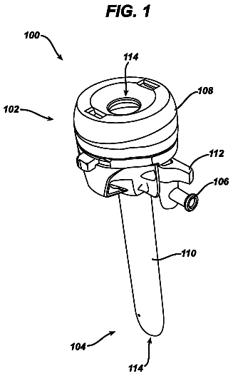
1 of 10 drawing sheets so far from the published document, cropped to the drawing. Every sheet is in the USPTO PDF.
What the patent claimed, word for word. All of it is now free to use.
The present disclosure is generally in the field of implantable medical devices, and more particularly relates to systems and methods of selectively removing a drug delivery device from a body cavity or lumen, such as the bladder.
U.S. Patent Application Publication No. 2007/0202151 and No. 2009/0149833 describe drug delivery devices for minimally invasive deployment and retention in a cavity or lumen of a patient, such as the bladder. The device may be configurable into a relatively low profile for minimally invasive deployment into the patient's body, and once implanted may spontaneously assume, or be configured to take, a relatively expanded profile to cause the device to be resistant to excretion and retained in the bladder over the course of delivering its drug payload to the body of the patient. In one embodiment, the patient subsequently must undergo an additional medical procedure to retrieve the drug-depleted device from the patient's body. Alternatively, a retrieval string may be attached to the deployed device to run transurethrally, but this is not viable for longer periods of deployment to due the risk of infection and/or inadvertent dislodgement.
It therefore would be desirable to provide devices and methods that avoid the necessity of retrieving the drug delivery device after the drug payload has been released from the device. It also would be desirable to facilitate selective removal of the device from the patient's bladder.
In one aspect, an implantable medical device for controlled drug delivery is provided that includes a drug formulation and a device structure that is deformable between a retention shape and a low profile shape for deployment in the bladder of a patient. The device structure includes at least one drug reservoir lumen into which the drug formulation is positioned. In some embodiments, the device structure has at least one non-degradable portion and at least one degradable link that is configured to degrade at a selected time in vivo to cause the device structure to lose the retention shape, e.g., collapse, so that the at least one non-degradable portion is excretable from the bladder. In other embodiments, the device structure includes at least one portion that is degradable upon contact with a physiological fluid adjacent to the device structure when deployed in vivo following the selective alteration of the composition of the physiological fluid adjacent to the device structure, the degradation of the at least one portion being effective to cause the device structure to lose the retention shape so that the device is excretable from the bladder.
In another aspect, methods are provided for the delivery of a drug to a patient that include deploying into the bladder of the patient through the urethra a device having a device structure housing a drug formulation of at least one drug, releasing at least a portion of the drug from the device structure into the bladder, and then changing the composition of urine in the bladder to trigger degradation of at least part of the device structure to enable the device structure or parts thereof to be excreted from the bladder.
FIG. 1 is a plan view of an embodiment of a drug delivery device.
FIG. 2 is a plan view of the drug delivery device shown in FIG. 1, illustrating the drug delivery device inside a deployment instrument.
FIG. 3 is a cross-sectional view of the drug delivery device shown in FIG. 1, taken along line 3-3 in FIG. 1.
FIG. 4 is a plan view of an embodiment of a drug delivery device.
FIG. 5 is a plan view of the drug delivery device shown in FIG. 4, illustrating the drug delivery device inside a deployment instrument.
FIG. 6 is an illustration showing the size of an embodiment of a drug delivery device in comparison to an approximation of the bladder trigone region.
FIG. 7 illustrates examples of shapes for a retention frame of a drug delivery device.
FIG. 8 illustrates examples of configurations for drug delivery devices having at least one drug delivery portion and a retention frame portion.
FIG. 9 illustrates a method of implanting a drug delivery device.
FIG. 10 is a sagittal view of a male patient, illustrating a drug delivery device exiting a deployment instrument into the bladder of the patient.
FIGS. 11A-B are plan views of one embodiment of the drug delivery device in its retention shape (FIG. 11A) and in a shape suitable for tolerable voiding (FIG. 11B).
FIG. 11C is an illustration of a wire segment that is suitable for spontaneous voiding from a bladder where the urethra has a diameter x.
FIGS. 12A-C are plan views of one embodiment of the drug delivery device in its retention shape (FIG. 12A), as the resorbable portion degrades (FIG. 12B), and in a shape suitable for tolerable voiding (FIG. 12C).
FIG. 13 illustrates three particular embodiments of the drug delivery device shown first in a retention shape in which the reservoir portions are connected by resorbable junctions and then shown in segments suitable for voiding after the junctions have been resorbed.
FIG. 14 is a cross-sectional plan view of an embodiment of a self-eliminating drug delivery device.
Implantable devices are provided that can be deployed, or implanted, into a lumen or body cavity of a patient, such as the bladder or another genitourinary site, for release of one or more drugs over an extended period.
The device may be deployed through a deployment instrument, such as a catheter or cystoscope, positioned in the urethra. The device is released into the bladder, and then drug is released from the device over an extended period. Advantageously, the device is configured so that it self-eliminates from the body so that an invasive retrieval procedure is unnecessary.
The self-eliminating device includes a device structure that is at least partially biodegradable. The device structure partially or completely degrades over a period of elimination, the onset of which is controlled or preprogrammed into the device. By controlling the onset of the period of elimination, the timing of the elimination of the device structure is controlled. For example, the device structure may be eliminated through complete or substantial degradation or resorption, through partial degradation of the device structure to form excretable pieces, through partial degradation of a retention feature such that the device structure assumes a shape suitable for excretion, or combinations thereof.
The implantable device is designed for deployment into and retention within the bladder. In a preferred embodiment, the device is flexible so that the device can be deformed for insertion, yet once implanted the device may resist excretion in response to the forces of urination or other forces. In particular embodiments, the drug delivery device is small enough to be inserted through a deployment instrument extending through the urethra into the bladder. Examples of suitable deployment instruments and techniques are described in U.S. Patent Application Publication No. 2011/0202036 to Boyko, et al., which is incorporated herein by reference. The devices and methods disclosed herein may be used in humans, whether male or female, adult or child, or in other mammals, such as for veterinary or livestock applications.
The devices and methods disclosed herein build upon those described in U.S. application Ser. No. 12/333,182, filed Dec. 11, 2008; U.S. application Ser. No. 12/825,215, filed Jun. 28, 2010; and U.S. application Ser. No. 12/972,364, filed Dec. 17, 2010, which are incorporated by reference herein. In one embodiment, the drug delivery device may deliver lidocaine or another anesthetic agent locally to the bladder over an extended period for the treatment of a condition such as IC/PBS, neurogenic bladder, or pain such as post-operative pain.
I. Elimination of the Implantable Drug Delivery Device
Generally, the implantable drug delivery devices include a drug formulation and a device structure. For purposes of this disclosure, the term "the device structure" generally refers to portions of the device other than the drug formulation. In the embodiment shown in FIGS. 1-3, for example, the device structure includes the device body 106, the retention frame 114, and any other components of the device 100 other than the drug formulation, such as any sealing plugs 120, any adhesive or filling materials used to construct or stabilize the device, and any radio-opaque portions used to facilitate detection of the device in the body. In such embodiments, the device structure may include the entire device 100 except for the solid drug tablets 112, which may be substantially or completely solubilized and released in vivo.
The device structure may be configured so that its elimination from the bladder may be initiated at a preselected time or within a preselected time window following implantation. The elimination of the device structure also may initiate in response to a change in the composition or characteristics of any fluid about the device, such as a change in the pH, temperature, pressure, or ionic strength of urine about the exterior of the device, within the interior of the device, or some combination thereof. The change in composition or characteristics may be initiated from either within the device or from within the implantation environment, in response to either the duration of exposure to physiological fluids in vivo or the introduction of an external agent into the implantation environment.
Controlling the onset of elimination permits delaying elimination of the device structure until after the device has substantially or completely released the drug. The elimination period may not be initiated until after the drug delivery period has ended or neared its end. Thus, the device may experience an initial period of drug release and a subsequent period of elimination, which may be controlled to overlap insignificantly or not at all. However, the drug release and elimination periods may partially or completely overlap, such as in embodiments in which the device begins degrading during drug release. For example, some remnants of solubilized drug or even portions of the drug formulation may remain in the device even as the device structure begins degrading. In cases in which the device structure degrades relatively slowly, it may be acceptable or even desirable to initiate degradation of the device structure before the drug has completely vacated the device.
Upon initiation of the elimination period, biodegradable portions of the device structure begin degrading. In some embodiments, the entire device structure is biodegradable. Over the period of degradation, the entire device structure degrades into remnants that are resorbed or excreted by the body. For example, both the device body and the retention frame may be substantially or completely biodegradable. Any sealing plugs, adhesives, or other materials used to construct the device also may be biodegradable.
As used herein, the term "bioerodible" or "biodegradable" means that the device, or part thereof, degrades in vivo by dissolution, enzymatic hydrolysis, erosion, resorption, or a combination thereof. In one embodiment, this degradation occurs at a time that does not interfere with the intended kinetics of release of the drug from the device. For example, substantial erosion of the device may not occur until after the drug formulation is substantially or completely released. In one embodiment, the device is erodible and the release of the drug formulation is controlled at least in part by the degradation or erosion characteristics of the erodible device body.
In other embodiments, at least a portion of the device structure is not biodegradable and is excreted from the body substantially intact. Upon degradation of the biodegradable portions of the device structure, the non-biodegradable portion may experience a change in size, shape, or configuration that enables the non-biodegradable portion to be excreted from the body. In embodiments, the device structure includes at least one non-degradable portion and least one degradable link that is configured to degrade at a selected time in vivo to cause the device structure to lose its retention shape so that the at least one non-degradable portion is excretable from the bladder.
For example, the non-biodegradable portion may be joined to or confined within the remainder of the device structure by a biodegradable portion, and upon degradation of the biodegradable portion, the non-biodegradable portion is released or separated from the remainder of the device structure for excretion. In embodiments, the biodegradable portions include links associated with one or more non-biodegradable portions. Once separated from the remainder of the device structure, the non-biodegradable portion may have a size, shape, and configuration that is suited for excretion from the body.
One example of such a configuration is an embodiment in which the device structure is configured to separate into two or more non-degradable segments, each segment sized and shaped to be excretable from the bladder, upon degradation of at least one degradable link that connects the two or more non-degradable segments. In this embodiment, the non-biodegradable portions are joined together by degradable links, such that the device body as a whole is relatively larger. Upon degradation of the links, the device body may break into multiple discrete pieces for excretion from the body.
Another example of such a configuration is an embodiment in which the entire device structure is biodegradable except for certain non-biodegradable components, such as a sealing plug or a radiopaque marker. The sealing plug or marker may be retained in the device structure, but upon degradation of the device structure, the sealing plug or marker may be released for excretion. In such a case, the sealing plug or marker is sized for excretion from the body so that once the sealing plug or marker is separated from the remainder of the device, the sealing plug or marker is readily excreted.
Another example of such a configuration is an embodiment in which the device structure is configured to assume, upon degradation of at least one degradable link, a flexible elongated shape that is excretable from the bladder. In one particular embodiment, the retention frame is configured, upon degradation of the at least one degradable link, to cease imparting the retention shape to the device structure. The degradation of the links causes the device structure to assume an elongated shape that is suited for excretion from the body.
In some embodiments, the time at which the bioerosion process is initiated can be controlled by selectively altering the composition of a physiological fluid adjacent to or within the device, such as urine. In embodiments, the device comprises a body that dissolves or erodes in viva upon a selective alteration in the composition of urine in the bladder. For example, the composition of urine may be changed by changing the pH, or introducing a catalyst or chelating agent into the bladder.
In some embodiments, the pH of the bladder environment (i.e., the urine) may be changed by introducing a material in the bladder that changes the composition of the urine adjacent to or within the device. The introduction of the material may be by oral administration. The material also may be introduced into the bladder via catheter through the urethra, with deployment of the drug delivery device or in a separate, later procedure. For example, the pH of the bladder environment may be changed upon the introduction of a pH-changing agent into the bladder or in response to a particular diet of the patient. Suitable drugs or supplements also may be administered to the patient to change the pH of urine. Thereafter, the exposure of the exterior surfaces of the device to the pH of the bladder environment may cause the device to degrade. In embodiments in which the device is water permeable, a change in the pH of the bladder environment may also affect the pH of fluid within the device, such that the device also degrades due to exposure of its interior surfaces to altered pH. In these embodiments, at least a portion of the device structure is formed of a material selected to degrade following a selected change in the pH of the physiological fluid adjacent to the device, such as urine.
In other embodiments, the composition of a physiological fluid adjacent to or within the device may be changed from within the device. In embodiments, the device structure is associated with at least one fluid-altering agent effective to cause the selective alteration of the composition of the physiological fluid, adjacent to or within the device. In one embodiment, the at least one fluid-altering agent is contained in at least one solid unit operable to release the fluid-altering agent into the physiological fluid upon conclusion of a release delay period. The solid unit can be coated or encapsulated with a release delaying material. In certain embodiments, the fluid-altering agent comprises one or more of the following: a pH-altering agent, a chelating agent, or a catalyst.
In some embodiments, the fluid-altering agent may comprise a pH-altering agent that changes the pH of the physiological fluid adjacent to or within the device from a first pH to a second pH; and at least one degradable portion of the device structure comprises at least one pH-responsive material that is stable in the presence of a fluid having the first pH and degrades in the presence of a fluid having the second pH.
For example, the device may house one or more release delayed, pH-altering pills. Examples include tablets having a pH-altering substance coated in a release delaying coating or a capsule having a pH-altering substance encapsulated in a release delayed capsule. The coating or capsule degrades or dissolves over a pre-selected period of time, controlling or delaying release of the pH-altering substance. Examples of suitable release delaying materials include enteric coating materials known in the art, such as those used in oral administration. For example, release of the pH-altering substance may be delayed until after most or all of the drug has been released. As the drug is released, the drug may be replaced with water or urine, such that the device houses primarily water or urine after most or all of the drug is released. The pH-altering pill may alter the pH of the water or urine within the device upon degradation or dissolution of its coating or encapsulation, causing the device to degrade from within. In particular, the device may degrade due to the exposure of its interior surfaces to the pH within the device. In embodiments in which the device is water permeable, the pH-altering pill also may affect the pH within the bladder, such that the device also degrades due to exposure of its exterior surfaces to altered pH. However, the device may primarily degrade from the inside out, as the relatively small volume of fluid within the device is maintained in close proximity to the device structure, keeping the concentrated high (or low) pH fluid within the device from becoming diluted with the potentially large volume of urine outside of the device.
In some embodiments, the device body or housing may comprise a pH sensitive or pH responsive polymer or copolymer. In some embodiments, the material may comprise ionizable functional groups in which charge is generated in response to pH. For example, the material may have functional groups which may ionize and acquire a positive or negative charge in a certain pH, such as --COOH, --NH.sub.2 groups. The change in charge may result in changes in the electrostatic forces within the material, enabling the erosion or dissolution of the material.
For example, the material may comprise natural materials such as the polysaccharides chitosan, alginate, and k-carrageenan. The material also may comprise synthetic polymers or gels that are pH sensitive including polyethleneimine, polylysine, poly-N,N-dimethyl aminoethyl methacrylamide, polyacryclid acid, or polymethacrylic acid (PMAA). The material may comprise PMAA and poly(ethlyene) glycol copolymers, poly(acrylic acid-co-octyl acrylate), poly(methacrylic acid-co-ethacrylic acid) PIMA-co-EA), 4-amino-N-(4,6-dimethyl-2-pyridinyl)benzene sulfonamide-N,N-dimethyl acrylamide, and poly-N-acryloyl-N-propylpiperazine (PNANP). In some embodiments, the material may comprise polymers or copolymers that in a non-ionized state are hydrophobic and water insoluble, and in an ionized state are water soluble.
In some embodiments, the drug delivery device may comprise a housing comprising a material that will degrade or erode when contacted by an enzyme or other catalyst. For example, the housing may comprise a material that will undergo hydrolysis in the presence of an enzyme. The enzyme may be naturally produced by the patient, may be produced by the patient in response to a substance administered to the patient, may be administered to the patient at or near the end of treatment, e.g., administered directly into the bladder (or other body lumen) where the device is placed, or stored on-board the delivery device. In one case, an enzyme is introduced into the bladder by an instillation procedure. In another case, the enzyme is stored in a tablet coated in a time-delaying coating.
There are a number of urinary enzymes found in humans and in animals. See Raab, W. P., "Diagnostic Value of Urinary Enzyme Determinations" Clinical Chemistry 18 (1):5-25 (1972). These may be from serum, kidneys, epithelial cells of the urogenital tract, or glandular secretions of the orogenital tract. Activators and inhibitors for such enzymes are also known to be found in urine. Examples of enzymes found in urine include amylase (normal range 2.6-21.2 IU), lactic dehydrogenase (17.5 mU/ml), leucine amino-peptidase (2 to 18 u/24 hr), urokinase (normal level 2068.+-.28 u/ml). The amounts of these or other enzymes in the urine in the bladder may be increased, for example, by instilling a particular dose and/or including the enzyme on-board the drug delivery device.
In another embodiment, a chelating agent is used to bind to an inhibitory ion which then allows an enzyme to degrade a polymeric housing material. The device also may dissolve or erode in response to the presence of an enzyme in the patient's urine, which may be introduced into the urine, may be naturally produced in vivo in response to the introduction of another substance into the urine, or may already be present in the urine but becomes effective to dissolve or erode the device upon the introduction of a chelating agent into the urine. Therefore, in some embodiments, at least a portion of the device structure is formed of a material selected to degrade following introduction of a chelating agent, into the physiological fluid adjacent to the device, that is effective to bind to an inhibitory ion which then allows an enzyme to degrade at least one portion of the device structure. For example, iron or another metal might be required to stabilize a polymer used to construct the device housing. The administered chelator may remove the iron and thereby cause the polymer to degrade. The chelating agent may be orally administered or delivered by an instillation procedure or stored on-board the drug delivery device (e.g., temporarily isolated from the degradable polymer, such as within a tablet coated in a release delaying coating).
II. The Implantable Medical Device
Generally, the implantable medical device includes a device structure and a drug formulation containing at least one drug.
In some embodiments, the device structure includes a drug reservoir portion and a retention frame portion. The drug reservoir portion includes a drug reservoir lumen into which the drug formulation is positioned. The retention frame portion, in some embodiments, includes a retention frame and a retention frame lumen, the retention frame being positioned at least partially within the retention frame lumen. In other embodiments, the retention frame portion includes a retention frame only. The device structure may include a device body that defines the drug reservoir lumen and the retention frame lumen.
In other embodiments, the device structure includes a drug reservoir portion, but no retention frame portion. In these embodiments, the drug reservoir portion is made from a material capable of imparting a retention shape to the device.
In some embodiments, the device structure is entirely biodegradable. In other embodiments, the device structure includes at least one biodegradable portion and at least one non-degradable portion. In particular embodiments, the device structure comprises at least one non-degradable portion and at least one degradable link. In one embodiment the resorbable or degradable links are positioned in the drug reservoir portion, for example, the drug reservoir lumen. In another embodiment, the resorbable or degradable links are positioned in the retention frame portion, for example, the retention frame lumen.
An embodiment of a drug delivery device 100 is illustrated in FIG. 1. The device 100 includes a drug reservoir portion 102 and a retention frame portion 104. In FIG. 1, the device 100 is shown in a relatively expanded shape suited for retention in the body, especially the bladder, and in FIG. 2 the device 100 is shown in a relatively lower-profile shape for deployment through the channel 202 of a deployment instrument 200, such as a cystoscope or catheter. Following deployment into the body, the device 100 may assume the relatively expanded shape to retain the drug delivery device in the body cavity or lumen, such as the bladder.
For the purposes of this disclosure, terms such as "relatively expanded shape," "relatively higher-profile shape," or "retention shape" generally denote any shape suited for retaining the device in the intended implantation location, including but not limited to the pretzel shape shown in FIG. 1 that is suited for retaining the device in the bladder. Similarly, terms such as "relatively lower-profile shape," "low-profile shape," or "deployment shape" generally denote any shape suited for deploying the drug delivery device into the body, including the linear or elongated shape shown in FIG. 2 that is suited for deploying the device through the working channel of a catheter, cystoscope, or other deployment instrument positioned in a lumen of the body, such as the urethra. In embodiments, the drug delivery device may naturally assume the relatively expanded shape and may be deformed, either manually or with the aid of an external apparatus, into the relatively lower-profile shape for insertion into the body. Once deployed, the device may spontaneously or naturally return to the initial, relatively expanded shape for retention in the body.
In the illustrated embodiment, the drug reservoir and retention frame portions 102, 104 of the drug delivery device 100 are longitudinally aligned and are coupled to each other along their length, although other configurations are possible. For example, the drug reservoir portion 102 may be attached to the retention frame portion 104 at discrete points but otherwise may be separate or spaced apart from the retention frame portion 104.
In particular, the drug delivery device 100 includes an elastic or flexible device body 106 that defines a drug reservoir lumen 108 and a retention frame lumen 110. The drug reservoir lumen 108 is designed to house a drug formulation, such as a number of solid drug tablets 112, to form the drug reservoir portion 102. The retention frame lumen 110 is designed to house a retention frame 114 to form the retention frame portion 104. The illustrated lumens 108, 110 are discrete from each other, although other configurations are possible.
As shown in the cross-sectional view of FIG. 3, the device body 106 includes a tube or wall 122 that defines the drug reservoir lumen 108 and a tube or wall 124 that defines the retention frame lumen 110. The tubes 122, 124 and lumens 108, 110 can be substantially cylindrical, with the drug reservoir lumen 108 having a relatively larger diameter than the retention frame lumen 110, although other configurations can be selected based on, for example, the amount of drug to be delivered, the diameter of the retention frame, and deployment considerations such as the inner diameter of the deployment instrument. The device body 106 may be formed integrally, such as via molding or extrusion, although separate construction and assembly of the tubes 122, 124 is possible. The wall 124 that defines the retention frame lumen 110 may extend along the entire length of the wall 122 that defines the drug reservoir lumen 108, so that the retention frame lumen 110 has the same length as the drug reservoir lumen 108 as shown, although one wall may be shorter than the other wall in other embodiments. Further, the two walls 122, 124 are attached along the entire length of the device in the illustrated embodiment, although intermittent attachment may be used, as shown, for example, in FIG. 4.
An aperture 118 may be formed through the wall 122 that defines the drug reservoir lumen 108. The aperture 118 may provide a passageway for releasing drug from the drug reservoir lumen 108 as further described below. However, the aperture 118 may be omitted in some embodiments.
As shown in FIG. 1, the drug reservoir lumen 108 is loaded with a number of drug units 112 in a serial arrangement. For example, between about 10 and about 100 drug units 112 may be loaded, such as between about 30 and about 70 drug units 112, or more particularly between about 50 and 60 drug units 112. However, any number of drug units may be used. The drug reservoir lumen 108 includes an entry 130 and an exit 132, which are shown as relatively circular openings at opposite ends of the drug reservoir lumen 108. The entry 130 provides ingress for the drug units 112 to be placed into the drug reservoir lumen 108 during device loading and assembly. Once the drug units 112 are loaded, at least two end plugs 120 block the entry 130 and exit 132. The end plugs 120 may be cylindrical plugs inserted into the entry 130 and the exit 132, each having a slightly larger outer diameter than an inner diameter of the drug reservoir lumen 108 so that the plugs substantially enclose the entry 130 and exit 132 and are snugly retained in position. In some cases, a number of end plugs 120 can be positioned in the entry 130 or the exit 132. The end plugs 120 may be silicone plugs. The end plugs 120 also may be omitted, in which case the entry 130 and exit 132 may be closed with a material, such as adhesive, that is placed in the drug reservoir lumen 108 in workable form and cures therein.
In some embodiments, the drug tablets 112 may not fill the entire drug reservoir lumen 108. In such embodiments, a filling material may be used to fill the remainder of the drug reservoir lumen 108. For example, the drug tablets 112 may be loaded in a central portion of the drug reservoir lumen 108 and the filling material may be loaded in the remaining end portions of the drug reservoir lumen 108. The filling material may be inserted into the end portions of the drug reservoir lumen 108 after the lumen is filled with the drug tablets 112. The filling material may be a polymeric material. The polymeric material may be placed in the drug reservoir lumen 108 in workable form and may cure therein. Suitable polymeric materials may cure at room temperature or in response to an external stimulus, such as heat. In some cases, the filling material may enclose the entry 130 and exit 132, in which case the end plugs 120 may or may not be provided. The filling material also may be a number of end plugs 120 inserted into the end portions of the drug reservoir lumen 108.
Once the drug units 112 are loaded, interstices 116 or breaks may be formed between adjacent drug units 112. The drug delivery device 100 may be relatively flexible or deformable despite being loaded with a solid drug, as each drug unit 112 may be permitted to move with reference to adjacent drug units 112. Along the length of the drug reservoir lumen 108, the drug units 112 may have the same composition or may vary in composition, and in some cases drug units 112 of different compositions may be in distinct reservoirs that are segregated, either axially or radially, along the length of the drug reservoir lumen 108.
The retention frame lumen 110 is loaded with the retention frame 114, which may be an elastic wire. The retention frame 110 may be configured to spontaneously return to a retention shape, such as the illustrated "pretzel" shape or another coiled shape. In particular, the retention frame 114 may retain the device 100 in the body, such as in the bladder. For example, the retention frame 114 may have an elastic limit and modulus that allows the device 100 to be introduced into the body in a relatively lower-profile shape, permits the device 100 to return to the relatively expanded shape once inside the body, and impedes the device from assuming the relatively lower-Profile shape within the body in response to expected forces, such as the hydrodynamic forces associated with contraction of the detrusor muscle and urination. Thus, the device 100 may be retained in the body once implanted, limiting or preventing accidental expulsion.
The material used to form the device body 106 may be elastic or flexible to permit moving the device 100 between deployment and retention shapes. When the device is in the retention shape, the retention frame portion 104 may tend to lie inside the drug reservoir portion 102 as shown, although the retention frame portion 104 can be positioned inside, outside, above, or below the drug reservoir portion 102 in other cases. The flexible material also allows the device body 106 to flex outward or circumferentially expand in response to a flow of pressurized gas through the drug reservoir lumen 108 during drug loading, as described below. The material used to form the device body 106 also may be water permeable or porous so that solubilizing fluid can enter the drug reservoir portion 102 to solubilize the drug units 112 once the device is implanted. For example, silicone or another biocompatible elastomeric material may be used.
In embodiments, the drug delivery device 100 of FIG. 1 is formed entirely from biodegradable materials. In other embodiments, the drug reservoir lumen 108 is formed from non-degradable materials, and the retention frame lumen 110 and retention frame 114 are formed form degradable materials. In further embodiments, the drug reservoir lumen 108 and retention frame lumen 110 are formed from non-degradable materials and the retention frame 114 is formed from a degradable material.
Another embodiment of a drug delivery device 400 is shown in FIG. 4. The device 400 includes a drug reservoir lumen 402 and a retention frame lumen 404. The drug reservoir lumen 402 is attached to discrete points on the retention frame lumen 404 but is otherwise separate or spaced apart from the retention frame lumen 404. In the drug reservoir lumen 402 are ball-shaped sealing structures 416 designed for retaining the drug (not shown) in the drug reservoir lumen 402. The retention frame 406 is disposed within the retention frame lumen 404. The retention frame lumen 404 is also coated with a polymer coating 408, which may be designed to control the onset of the elimination period. In FIG. 4, the device 400 is shown in a relatively expanded shape suited for retention in the body, and in FIG. 5 the device 400 is shown in a relatively lower-profile shape for deployment through the channel 500 of a deployment instrument, such as a cystoscope or other catheter. Following deployment into the body, the device 400 may assume the relatively expanded shape to retain the drug delivery device in the bladder.
In embodiments, the drug delivery device 400 of FIG. 4 is formed entirely from biodegradable materials, with the exception of the platinum wires, which may be omitted. In other embodiments, the drug reservoir lumen 402 is formed from non-degradable materials, and the retention frame lumen 404 and retention frame 406 are formed form degradable materials. In further embodiments, the drug reservoir lumen 402 and retention frame lumen 404 are formed from non-degradable materials and the retention frame 406 is formed from a degradable material.
One embodiment of the device is shown in FIGS. 11A-B. In FIG. 11A, device 900 includes a device body 902 and a retention frame 904. The retention frame consists of four wire segments 904A, 904B, 904C, and 904D that are connected by resorbable links 910A, 910B, and 910C. The links connect two adjacent wire segments. The ends of the wire segments include rounded or blunt end caps 912 so that the segment has no sharp ends or edges that could negate the tolerability of the segment within the bladder or during voiding. The end caps 912 may also facilitate securement of the wire segments together with the resorbable links. The device body 902 is in the form of a dual lumen elastomeric tube, which includes a retention frame lumen 906 and a drug reservoir lumen 908, which contains a drug payload (not shown) for release.
In one embodiment, the reservoir portion is formed of silicone and has two lumens, a smaller lumen for the retention wire and a larger lumen for the drug formulation.
In one embodiment, the wire segments are made of nitinol. Other biocompatible materials may be used to form the retention frame and wire segments. In one embodiment, the entire retention frame may be constructed of a resorbable material. In this case, holes in the wire lumen may be provided for the degradable material to be released out of the silicone tubing. In one example, the device may be directly implanted in the bladder during another invasive urological surgical procedure, which is useful when the wire form entirely made of degradable polymer does not have enough elastic property to be passed through the catheter of cystoscope for minimally invasive deployment.
The number of wire segments and links can vary. With a device embodiment having a retention frame that consists of multiple wire segments and multiple links, each segment will undergo less strain when stretched during the device deployment procedure as compared to a device embodiment having a retention frame that consists of only two wire segments and a single link.
The degradable links will eventually fail in vivo as a means to join adjacent wire segments. The particular choice of material and thickness of the link will determine how rapidly the link will fail in vivo. Following link failure, the elastomeric tube (e.g., the silicone reservoir portion) will easily bend at the junctions where the degradable links were initially placed, but the device will remain a single structure since the wire segments remain still within the small lumen. At this point, the device will no longer be able to stay in the bladder, and the shape of the device can be tortuous and overall linear.
As shown in FIG. 11A, the device initially has a relatively higher profile that facilitates retention of the device during delivery of the drug. As shown in FIG. 11B, following degradation/resorption of the links, the device assumes a relatively lower profile shape that is suitable for voiding of the device. FIG. 11C shows a wire segment that it is suitable for spontaneous voiding from a bladder where the urethra has a diameter x.
The description continues in the full USPTO document.
About 6,469 words. The USPTO PDF has it with every drawing.
Fees are due 3.5, 7.5 and 11.5 years after grant. This patent expired on April 8, 2026, so the fee marked "not paid" was the one that went unpaid.
TIME-SELECTIVE BIORESORBABLE OR COLLAPSIBLE DRUG DELIVERY SYSTEMS AND METHODS
Filed Oct 2011 · published Apr 2012Time-selective bioresorbable or collapsible drug delivery systems and methods
Filed Oct 2011 · granted Apr 2014Earlier publications, parents and continuations. None of them can still be enforced, or this patent would not be listed.
Prior art cited by the examiner or applicant. Useful when you check your own idea for novelty.
Everything on this page comes from the documents linked above.