Lapsed, fee not paid16 drawings
Vehicles & Drones · US 8,689,721 B2
Vertically installed spar and construction methods
A vertically installed Spar-type floater for offshore wind turbine and related construction method are provided.
US 8,689,742 B2 · Assignee: Hyundai Motor Company · Inventors: Myers; John William et al.
Sheet 1 of 5 from the published document. All sheets in the USPTO PDF
A coolant flow control system (100, 200) includes an integrated coolant flow control and heat exchange device (10, 50). The device includes a valve body part (20, 60) and a heat exchange part (30, 70). According to the system, all the coolant flow from the engine is delivered back to the engine after passing through the valve body part (20, 60) and then the heat exchange part (30, 70) in which it passes over the heat exchanger part (40, 80). The valve body part (20, 60) by positioning of the coolant flow wall (26, 66) allows multiple flow modes and coolant paths to branch out (or converge) from (or to) thereby controlling the flow in all coolant circuit branches.
(a) Technical Field The present disclosure relates to an integrated coolant flow control and heat exchange device for a vehicle. (b) Background Art Generally, a vehicle includes an internal combustion engine, a transmission, a unit heater, a radiator, a pump for delivering a coolant to the engine, and an engine control module. A typical cooling system used in a vehicle includes three main flow circuits: an engine bypass circuit, a circuit including a unit heater, and a circuit including a radiator. Coolant flow may be controlled by a simple traditional wax pellet fixed temperature thermostat or a more complex coolant control valve with a drive motor, which has been developed as a replacement to the traditional wax pellet type thermostat. The coolant control valve changes coolant flow within circuits based on a signal from a vehicle engine control module unit which is derived from engine
1 of 5 drawing sheets so far from the published document, cropped to the drawing. Every sheet is in the USPTO PDF.
What the patent claimed, word for word. All of it is now free to use.
(a) Technical Field
The present disclosure relates to an integrated coolant flow control and heat exchange device for a vehicle.
(b) Background Art
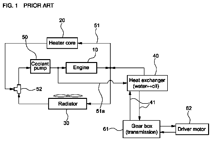
Generally, a vehicle includes an internal combustion engine, a transmission, a unit heater, a radiator, a pump for delivering a coolant to the engine, and an engine control module. A typical cooling system used in a vehicle includes three main flow circuits: an engine bypass circuit, a circuit including a unit heater, and a circuit including a radiator.
Coolant flow may be controlled by a simple traditional wax pellet fixed temperature thermostat or a more complex coolant control valve with a drive motor, which has been developed as a replacement to the traditional wax pellet type thermostat. The coolant control valve changes coolant flow within circuits based on a signal from a vehicle engine control module unit which is derived from engine coolant temperature.
The coolant control valve reduces engine warm up time by blocking coolant flow at initial cold start and also allowing the engine (coolant and oil) to operate at a higher temperature during normal driving to improve the engine lubricity by controlling the coolant temperature (and engine oil by default) within the engine at higher average temperatures.
The coolant control valve, however, does not provide a more rapid increase in the temperature of the transmission oil circuit because of positional limitation of a transmission oil cooler. More specifically, the transmission oil cooler is typically located in a radiator end tank (i.e., oil to liquid (coolant) type heat exchanger), in the air stream (i.e., air to oil cooler) in front of the vehicle engine cooling module, or both in series depending on transmission cooling demand requirements. Alternatively, it may be provided as a remotely mounted stand alone oil to coolant type cooler.
Such a transmission oil cooler is located within one of the three main flow circuits or an auxiliary circuit. Accordingly, as the coolant flows through multiple coolant circuits, the transmission oil cooler is not fully utilizing the maximum cooling potential available for transmission oil cooling.
Meanwhile, in case where the transmission oil cooler is located in the front end area of the vehicle (either in the radiator tank or air stream), during cold weather driving the transmission oil is typically cooled to the minimum operating temperature if allowed to flow within the heat exchangers provided for cooling. This causes the oil to warm up slowly and can also cause the oil to operate at a temperature which is lower than the temperature for optimum transmission oil lubricity. As a result, more transmission mechanical drag can be caused and vehicle fuel economy during cold weather conditions can be reduced. In case of the air to oil transmission oil cooler, if there is not a temperature bypass valve in the flow circuit, the oil in the cooler can get so cold and thick that the oil cooler may freeze and may not ever allow oil to pass through the cooler and, in some cases, may cause the transmission to be overheated and be damaged due to no oil flow through the transmission oil cooler.
Although devices and systems were proposed to increase the speed of transmission oil warm up, as disclosed in, for example, U.S. Pat. Nos. 6,182,749; 6,371,060; 6,997,143; 6,705,586; 6,796,375; 7,077,776 and 7,168,397, there is still a need for an improved device or system.
The above information disclosed in this Background section is only for enhancement of understanding of the background of the invention and therefore it may contain information that does not form the prior art that is already known in this country to a person of ordinary skill in the art.
The present invention provides an integrated coolant flow control and heat exchange device for a vehicle including an internal combustion engine, a transmission, a unit heater, a radiator, an engine control module, and a pump for delivering an engine coolant to the engine, the device comprising: a heat exchange part and a valve body part.
In one aspect, the present invention provides an integrated coolant flow control and heat exchange device. According to an embodiment, the integrated coolant flow control and heat exchange device for a vehicle, which includes an internal combustion engine, a transmission, a unit heater, a radiator, an engine control module, and a pump for delivering an engine coolant to the engine, comprises: a heat exchange part and a valve body part. The heat exchange part includes an outlet for discharging a coolant from the heat exchange part toward the pump, a first inlet for receiving a coolant coming from the radiator, a second inlet for receiving a coolant coming from the unit heater, and a heat exchanger provided inside the heat exchange part. The heat exchanger includes an inlet for receiving from a source of supply a vehicle fluid and an outlet for discharging the vehicle fluid from the heat exchanger toward the supply source by which the heat exchanger is in fluid communication with the supply source. The valve body part includes an inlet for receiving from a coolant coming from the engine, a first outlet for discharging a coolant from the valve body part toward the radiator, and a second outlet for discharging a coolant from the valve body part toward the unit heater.
The valve body part further includes a third outlet, the heat exchange part further includes a third inlet, and the third outlet of the valve body part is connected to the third inlet of the heat exchange part, thereby making the valve body part and the heat exchange part in fluid communication with each other which functions as the engine bypass so that none, some or all of the coolant inside the valve body part can be delivered to the heat exchange part to warm up and cool down the vehicle fluid inside the heat exchanger by heat exchange therebetween.
An integrated coolant flow control and heat exchange device according to another embodiment includes a heat exchange part and a valve body part. The heat exchange part includes an outlet for discharging a coolant from the heat exchange part toward the pump and a heat exchanger provided inside the heat exchange part. The heat exchanger includes an inlet for receiving a vehicle fluid from a supply source and an outlet for discharging a vehicle fluid from the heat exchanger toward the fluid supply source by which the heat exchanger is in fluid communication with the fluid supply source. The valve body part includes a first inlet for receiving a coolant coming from the engine, a second inlet for receiving a coolant coming from the radiator, and a third inlet for receiving a coolant coming from the unit heater.
The valve body part further includes an outlet, the heat exchange part further includes an inlet, and the outlet of the valve body part is connected to the inlet of the heat exchange part so that all of the coolant inside the valve body part can be delivered to the heat exchange part to warm up and cool down the vehicle fluid inside the heat exchanger by heat exchange there between.
In another aspect, the present invention provides coolant flow control systems including the above-described devices.
The above and other aspects and features of the invention are discussed below.
It is understood that the term "vehicle" or "vehicular" or other similar term as used herein is inclusive of motor vehicles in general such as passenger automobiles including sports utility vehicles (SUV), buses, trucks, various commercial vehicles, watercraft including a variety of boats and ships, aircraft, and the like, and includes hybrid vehicles, electric vehicles, plug-in hybrid electric vehicles, hydrogen-powered vehicles and other alternative fuel vehicles (e.g. fuels derived from resources other than petroleum). As referred to herein, a hybrid vehicle is a vehicle that has two or more sources of power, for example both gasoline-powered and electric-powered vehicles.
The above and other features of the present invention will now be described in detail with reference to certain exemplary embodiments thereof illustrated the accompanying drawings which are given herein below by way of illustration only, and thus are not imitative of the present invention, and wherein:
FIG. 1 shows an integrated coolant flow control and heat exchange device according to a first embodiment of the present invention;
FIG. 2 shows a coolant flow control system including the device of FIG. 1;
FIG. 3 shows an integrated coolant flow control and heat exchange device according to a second embodiment of the present invention;
FIG. 4 shows a coolant flow control system including the device of FIG. 3; and
FIG. 5 is a schematic diagram of an integrated coolant flow control and heat exchange device according to an embodiment of the present invention the heat exchange part of which is mounted on a supply housing of a vehicle and includes a plurality of heat exchangers.
It should be understood that the appended drawings are not necessarily to scale, presenting a somewhat simplified representation of various preferred features illustrative of the basic principles of the invention. The specific design features of the present invention as disclosed herein, including, for example, specific dimensions, orientations, locations, and shapes will be determined in part by the particular intended application and use environment.
In the figures, reference numbers refer to the same or equivalent parts of the present invention throughout the several figures of the drawing.
Hereinafter reference will now be made in detail to various embodiments of the present invention, examples of which are illustrated in the accompanying drawings and described below. While the invention will be described in conjunction with exemplary embodiments, it will be understood that present description is not intended to limit the invention to those exemplary embodiments. On the contrary, the invention is intended to cover not only the exemplary embodiments, but also various alternatives, modifications, equivalents and other embodiments, which may be included within the spirit and scope of the invention as defined by the appended claims.
FIG. 1 shows an integrated coolant flow control and heat exchange device
for a vehicle according to a first embodiment of the present invention. The vehicle includes an internal combustion engine, a transmission, a unit heater, a radiator, an engine control module, and a pump for delivering an engine coolant to the engine. The integrated coolant flow control and heat exchange device
includes a valve body part
and a heat exchange part (30). The valve body part
includes at least one inlet and at least one outlet. Preferably, as shown in FIG. 1, it may include an inlet (21), a first outlet (22), a second outlet (23), and a third outlet (24). The heat exchange part
includes at least one inlet and at least one outlet. Preferably, as shown in FIG. 1, it may include an outlet (31), a first inlet (32), a second inlet (33), and a third inlet (34).
The inlet
of the valve body part
is provided to receive a coolant coming from the engine. The first outlet
of the valve body part
is provided to discharge a coolant from the valve body part
toward the radiator. The second outlet
of the valve body part
is provided to discharge a coolant from the valve body part
toward the unit heater. The outlet
of the heat exchange part
is provided to discharge all coolant from the heat exchange part
toward the pump. The first inlet
of the heat exchange part
is provided to receive a coolant coming from the radiator. The second inlet
of the heat exchange part
is provided to receive a coolant coming from the unit heater. The third outlet
of the valve body part
is connected to the third inlet
of the heat exchange part
which takes the place of the traditional engine bypass circuit. The valve body part
controls the coolant flow so that none, some or all of the coolant can be delivered to the heat exchange part
to thereby warm up and cool down a vehicle fluid inside the heat exchanger
by heat exchange therebetween.
The valve body part
further includes a flow wall
for flow control. The flow wall
within the valve body part
functions to control the amount of a coolant flowing into various system circuits. For the design shown in FIG. 1, the flow wall
may be shaped like an inverted cup with varying opening shapes made in the cup which coincides with the different outlets. The flow wall
is capable of blocking all flow to an outlet or controlling any percent of flow up to full flow to any outlet depending on system requirements. The flow amount can be, suitably, controlled by unique controlled opening patterns located in the flow wall
designed to meet specific system coolant flow amounts based on circuit requirements.
The heat exchange part
further includes a (liquid to liquid) heat exchanger
provided inside the heat exchange part (30). The heat exchanger
includes at least one inlet and at least one outlet. Preferably, it may include an inlet
and an outlet (42), as shown in FIG. 1. The inlet
is provided ideally for receiving a vehicle fluid from a supply source and the outlet
is provided for discharging the vehicle fluid from the heat exchanger (40). Examples of the vehicle fluid may include, but not limited to, a transmission oil, an engine oil, a power steering, a differential oil, a trans axle oil, electric cooler, converter oil, generator oil, a/c cabin refrigerant or any kind of fluids for use in any other system or device within the vehicle requiring cooling or warming. The vehicle fluid can be any type of fluids, gases or mixtures requiring cooling or heating such as oils, refrigerants, coolants or salts. Only for illustration purposes, the device
shown in FIG. 1 (and other drawings) is described to include a transmission oil as the vehicle fluid and a transmission as the supply source.
The device
further includes an actuator
on or near the valve body part (20). The actuator
is configured to operate in response to a control signal from the engine control module so as to selectively operate the movement of the flow wall
which opens, varies and/or closes the flow through the outlet (22, 23, 24) of the valve body part
in response to respective control signals from the engine control module. The actuator
can be realized in various forms known in the art. One example is a step motor controlled by a signal received from the engine controller which, depending on coolant and oil temperatures, can control the flow wall
position to optimize coolant flow within the circuits.
Preferably, the device
further includes a pressure cap
on a portion of the heat exchange part (30). The pressure cap (38), similar to a traditional spring actuated pressure cap, may function as a controller of the coolant operating pressure within the system and/or as an access point in the system for adding coolant for system servicing.
The shape, size, and position of the valve body part
are not limited to particular ones and can be independently changed according to design choices and/or operational conditions. For instance, the valve body part
may have a circular cross section.
Likewise, the position, shape and size of the inlet
and the first, second, and third outlets (22, 23, 24) of the valve body part (20), the outlet
and the first, second, and the third inlets (32, 33, 34) of the heat exchange part (30), and the inlet
and the outlet
of the heat exchanger
are not limited to particular ones and can be independently changed according to design choices and/or operational conditions. For example, the inlets (21, 32, 33, 34, 41) and the outlets (22, 23, 24, 31, 42) each may have a circular cross section. Preferably, some or all of the inlets (21, 32, 33, 34, 41) and the outlets (22, 23, 24, 31, 42) may be designed to have identical or different shapes and sizes. Suitably, the third outlet
and the third inlet
may be formed integrally or separately.
In addition, additional ports may be added to supply a coolant to other branch coolant circuits (not shown). For example, there may be an additional outlet(s) similar to the outlet
which can flow a coolant to other possible circuit needs (i.e.: engine cooler, power steering cooler, electric cooler fluid or any other systems or devices provided within a vehicle for cooling or warming).
The valve body part
may be formed integrally with the heat exchange part
while being in fluid communication with the heat exchange part (30). Alternatively, it may be located remotely from the heat exchange part
while being in fluid communication with the heat exchange part (30).
Also, the heat exchange part may include a plurality of heat exchangers. For example, as shown in FIG. 5, the heat exchange part
may include two heat exchangers (131, 132).
Further, the heat exchange part
may, suitably, be mounted on a predetermined portion or portions of a supply source housing
(e.g., transmission housing) while being in fluid communication with the supply source housing (102). Alternatively, it may be placed remotely from the supply source housing
while being in fluid communication with the supply source housing (102).
In an exemplary embodiment, as shown in FIG. 5, the heat exchange part
may be mounted on a portion of the supply source housing
(e.g., transmission housing). The heat exchange part
may have a first heat exchanger
and a second heat exchanger (132). In this case, although not shown, the valve body part
may be disposed in the above-described manner.
In this embodiment, the first heat exchanger
may be in fluid communication with the supply housing
through a first heat exchanger inlet
and a first heat exchanger outlet (152), which are similar to the inlet
and outlet (42), respectively. The first heat exchanger inlet
and outlet
can be formed either in the supply source housing
while being in fluid communication with the first heat exchanger
or in the other vehicle system(s) while being in fluid communication with the first heat exchanger (131). The second heat exchanger
may fluid communicate with the supply source housing
through a second heat exchanger inlet (not shown) and a second heat exchanger outlet (not shown) which are similar to the first exchanger inlet
and outlet (152). Alternatively, the second heat exchanger
may be designed to be in fluid communication with additional vehicle systems (not shown) that need either cooling or warming. As discussed above, the mounting position of the heat exchange part and the number of the heat exchangers located within the heat exchange part can be adjusted according to design choice and operational condition.
The term "vehicle fluid" used herein refers to any type of fluids for use in any systems or devices within a vehicle for cooling or warming purpose. Accordingly, it may be, e.g., oils, refrigerants, coolants or salts and may be in the form of liquid, gas, or mixture thereof. Non-limiting examples of the fluid include a transmission oil, an engine oil, a power steering oil, a differential oil, a trans axle oil, an electric cooler fluid, a converter oil, a generator oil, and an a/c cabin refrigerant.
Referring to FIG. 2, a coolant flow control system
including the integrated coolant flow control and heat exchange device
according to the first embodiment is described.
The coolant control system
includes an integrated coolant flow control and heat exchange device (10), an engine (101), a pump (103), a radiator (104), a unit heater
and a throttle body warmer (106).
The integrated coolant flow control and heat exchange device
includes a valve body part
and a heat exchange part
in fluid communication with the valve body part (120). The valve body part
is in fluid communication with the engine
and receives all of the coolant coming from the engine (101). The heat exchange part
includes a first heat exchanger
for receiving, accommodating and discharging a first vehicle fluid. The first vehicle fluid inside the first heat exchanger
is heat exchanged with the coolant inside the heat exchange part (130), thereby being able to be warmed or cooled.
The pump
is in fluid communication with the engine
for delivering a coolant to the engine (101).
The radiator
is provided in a first branch coolant circuit
and is in fluid communication with the valve body part
so as to receive none, some or all of the coolant coming from the valve body part (120).
The unit heater
and throttle body warmer
are provided in a second branch coolant circuit
and are in fluid communication with valve body part
so as to receive none, some or all of the coolant coming from the valve body part (120).
The engine bypass
is in a third branch coolant circuit
and in fluid communication between the valve body part
and the heat exchange part
so as to receive none, some or all of the coolant coming from the valve body part (120). The third branch circuit
can either be formed integrally between the valve body part
and heat exchange part
or be formed separately with a communication device.
The coolant passing through the first branch coolant circuit
is delivered back to the pump
after passing through the heat exchange part (130). The coolant passing through the second branch coolant circuit
is delivered back to the pump
after passing through the heat exchange part (130). The coolant passing through the third branch coolant circuit
is delivered back to the pump
after passing through the heat exchange part (130). The number of the branch coolant circuits (110, 111, 112) controlled by the device
can be adjusted as long as packaging space permits and proper function is ensured and/or depending on design choice.
Preferably, the system may further include additional branch coolant circuit(s) that can flow a fluid(s) to and from other possible supply source(s) requiring cooling and/or warming depending on cooling system design and requirements. The coolant flow would be controlled through the branch coolant circuits by the valve body part
of the device (10).
Suitably, the system may further include additional heat exchanger(s). Preferably, the heat exchanger(s) may be connected in parallel or series with existing circuits like the throttle body
connected to the unit heater (105), may be connected in parallel or series with at least one of the branch coolant circuits (110, 111, 112), or may have its own independent branch circuit but deliver the coolant back to the pump after passing through the heat exchange part (130).
As discussed above, as shown in FIG. 5, the heat exchange part
may further include a second heat exchanger
for receiving, accommodating and discharging a second vehicle fluid. The second vehicle fluid inside the second heat exchanger
is heat exchanged with the coolant inside the heat exchange part (130), thereby being able to be warmed or cooled. The second vehicle fluid may be identical to or different from the first vehicle fluid. The second vehicle fluid can be any type of vehicle fluid for use in systems or devices within a vehicle for cooling or warming purpose. Examples of the second vehicle fluid include, but not limited to, a transmission oil, an engine oil, or a power steering oil, a differential oil, a trans axle oil, an electric cooler fluid, a converter oil, a generator oil, an a/c cabin refrigerant.
As discussed above, the first heat exchanger
can be positioned on a portion of the supply source housing (e.g., transmission housing) (102), in which case the fluid path would require no additional connecting hardware.
FIG. 3 shows an integrated coolant flow control and heat exchange device
for a vehicle according to a second preferred embodiment of the present invention. The integrated coolant flow control and heat exchange device
includes a valve body part
and a heat exchange part (70).
The device
according to the second embodiment is similar to the device
according to the first embodiment except for some aspects. One difference is that the device
has the valve body part
located upstream of the heat exchange part
and is down stream of all other branch coolant circuits within the system such that the coolant leaving the engine flows through all branch coolant circuits before entering the valve body part (60). Another difference is that the device
requires an additional external branch coolant circuit for the engine bypass
flow and an additional inlet pipe (i.e., first inlet (61)) and all the branch coolant circuits are pressurized by the pump.
The valve body part
includes at least one inlet and at least one outlet. Preferably, as shown in FIG. 3, it may include a first inlet (61), a second inlet (62), a third inlet (63), and an outlet (64). The heat exchange part
includes at least one inlet and at least one outlet. Preferably, it may include an outlet
and a first inlet (74).
The first inlet
of the valve body part
is provided for receiving a coolant coming from the engine. The second inlet
of the valve body part
is provided for receiving a coolant coming from the radiator. The third inlet
of the valve body part
is provided for receiving a coolant coming from the unit heater. The outlet
of the heat exchange part
is provided for discharging all the coolant from the heat exchange part
toward the pump. The first inlet
of the heat exchange part
is provided to receive all the coolant coming from the valve body part (60). The outlet
of the valve body part
is connected to the inlet
of the heat exchange part
so that all of the coolant inside the valve body part
can be delivered to the heat exchange part
to thereby warm up and cool down the supply source fluid (e.g., transmission oil) inside the heat exchanger
by heat exchange therebetween.
The valve body part
further includes a flow wall (66). The flow wall
functions to control the amount of a coolant flowing from various system circuits. The flow wall
may be shaped like, e.g., an inverted cup with varying opening shapes made in the cup which coincides with the different inlets. The flow wall
is capable of blocking all flow from the inlets or controlling any percent of flow up to full flow through any inlet depending on system requirements. The flow amount can be, suitably, controlled by unique controlled opening patterns located in the flow wall designed to meet specific system coolant flow amounts based on circuit requirements.
The heat exchange part
further includes a heat exchanger
provided inside the heat exchange part (70). The heat exchanger
includes at least one inlet and at least one outlet. Preferably, it may include an inlet
and an outlet (82), as shown in FIG. 3. The inlet
is provided for receiving a vehicle fluid (e.g., transmission oil) from a supply source (e.g., transmission) and the outlet
is provided for discharging the vehicle fluid from the heat exchanger
toward the supply source, by which the heat exchanger
is in fluid communication with the supply source.
The device
further includes an actuator
on or near the valve body part (60). The actuator
is configured to operate in response to a control signal from the engine control module so as to selectively operate the movement of the flow wall
within the flow body part
in response to the control signals from the engine control module. The actuator
can be realized in various forms known in the art. One example is a step motor controlled by a signal received from the engine controller which, depending on coolant and oil temperatures, can control the flow wall
position to optimize coolant flow within the various circuits.
Preferably, the device
further includes a pressure cap
on a portion of the heat exchange part (70). As discussed above, the pressure cap (78), like the pressure cap (38), may function as a controller of the coolant operating pressure within the system and/or as an access point in the system for adding coolant for system servicing.
The shape, size, and position of the valve body part
are not limited to particular shape, size, and location and can be adjusted according to design choices and/or operational conditions. For instance, the vertical direction cross section of the valve body part
may be circular such that the flow wall
can rotate within the valve body part
and control the flow amount within the various branch coolant circuits.
Likewise, the position, shape and size of the inlets (61, 62, 63) and the outlet
of the valve body part (60), the outlet
and the first inlet
of the heat exchange part (70), and the inlet
and the outlet
of the heat exchanger
are not limited to particular ones and can be independently adjusted according to design choices and/or operational conditions. For example, the inlets (61, 62, 63, 74, 81) and the outlets (64, 71, 82) each may have a circular cross section. Preferably, some or all of the inlets (61, 62, 63, 74, 81) and the outlets (64, 71, 82) may be designed to have identical or different shapes and sizes. Suitably, the outlet
and the inlet
may be formed integrally or separately. For example, the entire valve body part
can be integrated together with the heat exchange part
as one integral part with no wall separating the two parts.
Further, additional ports may be added to receive a coolant from other branch coolant circuits (not shown). For example, there may be an additional inlet(s) similar to the inlet
which can receive a coolant from other possible branch coolant circuits.
Also, the heat exchanger part may include a plurality of heat exchangers. For example, as shown in FIG. 5, the heat exchange part
may include two heat exchangers (231, 232).
Further, the heat exchange part
may, suitably, be mounted on a predetermined portion or portions of a supply source housing
(e.g., transmission housing) while being in fluid communication with the supply source housing (202). Alternatively, it may be placed remotely from the supply source housing
while being in fluid communication with the supply source housing (202).
Likewise, the valve body part
may be formed integrally with the heat exchange part
while being in fluid communication with the heat exchange part (70). Alternatively, it may be located remotely from the heat exchange part
while being in fluid communication with the heat exchange part (70).
In an exemplary embodiment, as shown in FIG. 5, the heat exchange part
may be mounted on a portion of the supply source housing
(e.g., transmission housing). The heat exchange part
may have a first heat exchanger
and a second heat exchanger (232). In this case, although not shown, the valve body part
may be disposed in the above-described manner.
In this embodiment, the first heat exchanger
may be in fluid communication with the supply housing
through a first heat exchanger inlet
and a first heat exchanger outlet (252), which are similar to the inlet
and outlet (42), respectively. The first heat exchanger inlet
and outlet
can be formed either in the supply source housing
while being in fluid communication with the first heat exchanger
or with other vehicle system(s) while being in fluid communication with the first heat exchanger (231). The second heat exchanger
may be in fluid communication with the supply source housing
through a second heat exchanger inlet (not shown) and a second heat exchanger outlet (not shown) which are similar to the first exchanger inlet
and outlet (252). Alternatively, the second heat exchanger
may be designed to be in fluid communication with additional vehicle systems (not shown) that need either cooling or warming. As discussed above, the mounting position of the heat exchange part and the number of the heat exchangers located within the heat exchange part can be adjusted according to design choice and operational condition.
Referring to FIG. 4, a coolant flow control system
for a vehicle including the integrated coolant flow control and heat exchange device according to the second embodiment is described.
The coolant flow control system
includes an integrated coolant flow control and heat exchange device (50), an engine (201), a pump (203), a radiator (204), a unit heater
and a throttle body warmer (206).
The integrated coolant flow control and heat exchange device
includes a valve body part
and a heat exchange part
in fluid communication with the valve body part (220). The heat exchanger part
includes therein a first heat exchanger
for receiving, accommodating and discharging a first vehicle fluid. The first vehicle fluid inside the first heat exchanger
is heat exchanged with the coolant inside the heat exchange part (230), thereby being able to be warmed or cooled.
The pump
is in fluid communication with the engine
for delivering a coolant to the engine (201).
The radiator
is provided in a first branch coolant circuit
and is in fluid communication with the engine so as to receive some or all of the coolant coming from the engine (201).
The unit heater
is provided in a second branch coolant circuit
and is in fluid communication with the engine so as to receive some or all of the coolant coming from the engine (201).
The engine bypass
is provided in a third branch coolant circuit
and is in fluid communication with the engine so as to receive some or all of the coolant coming from the engine (201).
All the coolant passing through the first branch coolant circuit
is delivered back to the pump
after passing through the valve body part
and then the heat exchange part (230). All the coolant passing through the second branch coolant circuit
is delivered back to the pump
after passing through the valve body part
and then the heat exchange part (230). All the coolant passing through the third branch coolant circuit
is delivered back to the pump
after passing through the valve body part
and then the heat exchange part (230). This would also be true for any other additional branch coolant circuits that may be part of an engine cooling system.
Preferably, the system may further include at least one additional branch coolant circuit(s) that can flow a fluid(s) to and from other possible supply source(s) requiring cooling or warming depending on cooling system design and requirements.
Suitably, the system may further include additional heat exchanger(s). Preferably, the additional heat exchanger(s) may be connected in parallel or series with existing circuits like the throttle body
connected to the unit heater (205), may be connected in parallel or series with at least one of the branch coolant circuits (210, 211, 212), or may have its own independent branch circuit but deliver the coolant back to the pump after passing through the valve body part
and the heat exchange part (230).
As discussed above, as shown in FIG. 5, the heat exchange part
may further include a second heat exchanger
for receiving, accommodating and discharging a second vehicle fluid. The second vehicle fluid inside the second heat exchanger
is heat exchanged with the coolant inside the heat exchange part (230), thereby being able to be warmed or cooled. The second vehicle fluid may be identical to or different from the first vehicle fluid. The second vehicle fluid can be any type of vehicle fluid for use in systems or devices within a vehicle for cooling or warming purpose. Examples of the second vehicle fluid include, but not limited to, a transmission oil, an engine oil, or a power steering oil, a differential oil, a trans axle oil, an electric cooler fluid, a converter oil, a generator oil, an a/c cabin refrigerant.
As discussed above, the first heat exchanger
can be positioned on a portion of the supply source housing (e.g., transmission housing) (202), in which case the fluid path would require no additional connecting hardware.
According to the coolant flow control system (100, 200), the fluid (transmission oil) can be warmed or cooled quickly. More particularly, in the case of warm up mode, all the coolant from all cooling branch circuits (110, 111, 112, 210, 211, 212) which is warmer than the supply source fluid (transmission oil), is controlled to pass over the heat exchanger (131, 231) before returning to the pump (103, 203), thereby warming the supply source fluid (transmission oil) with the waste heat produced from other vehicle areas. In addition to the quick warming, it can maintain the average supply source fluid (transmission oil) temperature higher during cold weather driving with less supply source fluid (transmission oil) temperature variation, thus improving fuel economy due to the improvements in oil lubricity within the supply source device (transmission) and seal durability.
On the other hand, in case of cooling mode, all the coolant from the engine, which is cooler than the supply source fluid (transmission oil), is controlled to pass over the heat exchanger (131, 231) before returning to the pump (103, 203), thereby cooling the supply source fluid (transmission oil). In addition to the quick cooling, it can maintain the average supply source fluid (transmission oil) temperature near the optimum temperature or within the permissible temperature, thus improving fuel economy due to the improvements in oil lubricity within the transmission and seal durability.
In addition to the above-discussed valve body coolant control features, the valve body part (20, 60) achieved by controlling the positioning of the flow wall (26, 66) within the valve body (20, 60) provides the following features:
1) Rapid Engine Warm-Up Mode: In this fully blocked mode, the flow wall (26, 66) can be positioned within the valve body (20, 60) so as to allow no coolant flow within any circuit or the engine. This condition is desired on cold engine start up where all heat generated within the engine is used to rapidly warm up the coolant and improve cold start fuel economy.
2) Default/Service Fill Mode: In the Default/Service Fill mode, at the position at which the flow wall (26, 66) is located when the actuator (25, 65) loses the signal from the engine control module, the flow wall (26, 66) will reach a position which will allow flow through all branches of the coolant flow control system and protect the vehicle from overheating during operation and improve service draining and filling process during vehicle servicing.
Another unique feature of the integrated coolant flow control and heat exchanger devices (10, 50) is that any coolant flow in any of the coolant branch circuits must pass through the heat exchange part (130, 230) and then by the heat exchanger before returning to the pump (103, 203), thereby maximizing the heat exchange performance.
According the present devices and systems, the vehicle fluid (e.g. transmission oil) can be warmed up or cooled down quickly. Also, with the integrated design of the present invention, space utilization can be improved and the number of components consisting of the system can be reduced.
The invention has been described in detail with reference to preferred embodiments thereof. However, it will be appreciated by those skilled in the art that changes may be made in these embodiments without departing from the principles and spirit of the invention, the scope of which is defined in the appended claims and their equivalents.
About 6,526 words. The USPTO PDF has it with every drawing.
Fees are due 3.5, 7.5 and 11.5 years after grant. This patent expired on April 8, 2026, so the fee marked "not paid" was the one that went unpaid.
INTEGRATED COOLANT FLOW CONTROL AND HEAT EXCHANGER DEVICE
Filed Nov 2009 · published May 2011Integrated coolant flow control and heat exchanger device
Filed Nov 2009 · granted Apr 2014Earlier publications, parents and continuations. None of them can still be enforced, or this patent would not be listed.
Prior art cited by the examiner or applicant. Useful when you check your own idea for novelty.
Everything on this page comes from the documents linked above.