 Lapsed, fee not paid18 drawings
Industrial Equipment · US 8,689,599 B2
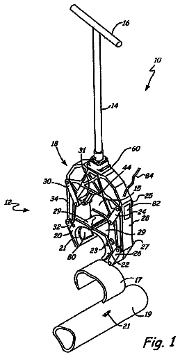
Clamp and repair tool
A system for repairing a pipe including a tool, a programmable logic controller and a patch.
US 8,689,614 B2 · Assignee: Highland Biosciences Limited · Inventors: Day; Richard et al.
Sheet 1 of 33 from the published document. All sheets in the USPTO PDF
The present invention provides a method for the real-time continuous monitoring of a change or density and/or viscosity within a test sample. Such methods can be used to determine the occurrence of a chemical reaction within a test sample where the same causes and increase or decrease in the density and/or viscosity of the sample due to, for example, a gelation, precipitation or coagulation occurring within the test sample. There is further provided a multi-resonator apparatus for use in measuring the density and/or viscosity of a test sample in which the multi-beam resonator is immersed.
The viscosity of a fluid may be measured using a viscometer. Viscometers measure the properties of a fluid under conditions where the fluid remains stationary and an object, such as a vibratory element moves through it. The measurement of the viscosity can be determined based on the drag caused by the relative motion of the fluid and surface. One specific type of viscometer is a vibration viscometer. Vibration viscometers typically function by allowing the measurement of the dampening of an oscillating electrochemical resonator which is immersed in the fluid of which the viscosity is to be determined. The greater the viscosity of the fluid, the larger the dampening effect imposed on the resonator. A change in the density or viscosity of a fluid can accompany or be the result of the occurrence of a chemical reaction. A change in the density or viscosity of a test sample can, in particular
1 of 33 drawing sheets so far from the published document, cropped to the drawing. Every sheet is in the USPTO PDF.
What the patent claimed, word for word. All of it is now free to use.
The present invention provides an improved sensor apparatus for the measurement of assays and chemical reactions wherein a change in viscosity and/or density, by for example, gellation, precipitation, agglutination or coagulation, occurs. In particular, there is provided a biosensor for use in the real time measurement of an assay, such as an endotoxin assay used to determine the presence of microbial contaminants in a test sample, the apparatus allowing the viscosity and/or density of the sample to be measured continuously as the assay progresses. The invention further extends to methods for performing such assays, and further to the use of said apparatus in the performance of such methods.
The viscosity of a fluid may be measured using a viscometer. Viscometers measure the properties of a fluid under conditions where the fluid remains stationary and an object, such as a vibratory element moves through it. The measurement of the viscosity can be determined based on the drag caused by the relative motion of the fluid and surface.
One specific type of viscometer is a vibration viscometer. Vibration viscometers typically function by allowing the measurement of the dampening of an oscillating electrochemical resonator which is immersed in the fluid of which the viscosity is to be determined. The greater the viscosity of the fluid, the larger the dampening effect imposed on the resonator.
A change in the density or viscosity of a fluid can accompany or be the result of the occurrence of a chemical reaction. A change in the density or viscosity of a test sample can, in particular, occur during the performance of assays commonly used in areas such as haematology where blood clotting, or coagulation reactions are measured, in immunology where immunoassays are performed, and further for more general screening, such as high throughput screening, for example to detect the presence of a contaminant or analyte in a sample.
One example of such an assay which uses a change in density or viscosity of a test sample in order to provide result is assay based test to determine the presence of bacterial endotoxin in a test sample.
Bacterial endotoxin, such as lipopolysaccaharide (LPS), is a fever producing product of gram negative bacteria. Endotoxins typically have a hydrophobic core which is bound to repeating oligosaccharide side chains. When present in the bloodstream, even in low levels, endotoxins can cause fever, shock, hypotension, raised erythrocyte count, and disseminated intravascular coagulation. If the endotoxin is present in a sufficient high level in the bloodstream, it can cause death.
The US Food and Drug Administration department (FDA) requires drugs and pharmaceutical compounds which are to be administered to a subject either by injection, or intravenously, to undergo an endotoxin test prior to their administration. Furthermore, prosthetic devices, such as heart valves or hip replacements also require such an endotoxin test. There is therefore an on-going need to provide accurate testing to determine the presence of endotoxin within a test sample.
The traditional test used to identify the presence of pyrogens, such as endotoxin, was the rabbit pyrogen test. This test, which dates back to 1942, suffered the disadvantages of being both slow and expensive to perform. Subsequent to this, Levin and Bang discovered that blood cells (amebocytes) which were derived from the horseshoe crab (Limulus polyphemus), contained a clotting agent that attaches to the endotoxins produced by gram-negative bacteria. This clotting agent was identified as Limulus amoebocyte lysates, which is commonly abbreviated to "LAL".
LAL was used to develop a number of gellation based clotting tests which detect and quantify the presence of endotoxin within a test sample. A number of such LAL-based tests are currently used commercially to determine the presence and quantity of endotoxin within a sample.
For example, the gel-clot test is a sample test that uses a lysate preparation of Limulus polyphemus blood to give a positive/negative answer by means of the presence or absence of gel-clot formation within a test tube or vial. The presence of endotoxin results in clotting, and hence, this change of state can be visually determined by inverting the vessel in which the reaction has occurred.
Preparations of LAL lysate are commercially available in different sensitivities, to give a qualitative. In addition, testing kits that contain LAL reagents may be provided in `ready to use` tube vials, which allow for diluted samples to be added to the vials so that the assay can be performed within them.
Gel-clot kits are frequently used for field testing. They may also be used in laboratories where small sample throughput is required. The maximum sensitivity of the gel-clot test is generally a level of around 0.03 EU/ml of endotoxin in a sample. However, there are disadvantages associated with such tests, in particular the cost as a large quantity of LAL reagent must be used for each sample. Furthermore, the results from the gel-clot LAL test are subject to human interpretation, as the results are visually determined. An assay based on the subjective determination of a gel-clot is particularly difficult to automate, hence determining the result of the gel-clot test in this way may introduce a greater degree of error into determining the results of the test, and may further lead to the increased risk of reporting a false negative result.
A further technique used to identify endotoxin in a sample is by means of optical analysis: chromogenic or turbidometric methods. These methods can be fully automated, and further have the advantage of providing quantitative results. These tests can also use a "kinetic" approach, measuring a response as a function of time can be obtained, rather than waiting for the entire reaction to complete before determining the result.
The turbidometric method is a sensitive LAL-based method used for determining endotoxin levels in a sample, with a maximum sensitivity of 0.001 EU/ml. However, for this level of sensitivity the methodology requires the use of costly, large and sensitive laboratory equipment, and therefore analysis of this type is restricted. Equipment which allows for "kinetic" LAL testing to be performed on a smaller scale, albeit with lower sensitivity is commercially available; however such systems (for example ENDOSAFE.TM., Charles River Laboratories) use microfluidics and optical technology to analyse the sample within a tiny sampling area. Such approaches have limited sensitivity and poor precision due to the short pathlength of the interrogating light through the sample. The resulting method will be suffer increases in analysis time and decreases in precision with a desirable reduction in sample volume that enable reductions in reagent and sample usage
A quartz crystal microbalance (QCM) may be used for detecting the end-point of a gellation or agglutination reaction. For example a LAL assay can be performed by immersing the crystal within a test sample undergoing a LAL reaction. A key failing of resonating crystals is caused due to the high frequency of resonance of a pure piezoelectric resonator (for example in European Patent No 0,304,283 B1 these values are in the order of 6-12 MHz). The depth of the liquid probed by the vibration will therefore be very small, and so it is to be expected that the signal will also be very small. However, WO 2005/114138 teaches that applying a texture to the surface of a planar resonating device operating at a megahertz frequency improves the viscosity and density measuring capability. The textured surface creates an entrapped layer of liquid close to the sensor surface. In the case of monitoring of biological reactions, this not ideal because the sensor now responds according to the kinetics of the diffusion of the reagents and reaction products in the entrapped layer, rather than responding to the reaction in the bulk. In order to address these shortcomings in the devices known in the prior art, the inventors have identified that ideally a lower frequency resonator, for example of 400 kHz or less, would be optimal for the measurement of biological reactions.
U.S. Pat. No. 6,401,519 teaches how mechanical oscillators can be used to analyse the properties of fluids. Different viscosities and density values present different characteristic frequency/amplitude responses. A twin beam cantilevered tuning fork as shown in U.S. Pat. No. 6,401,519 suffers from energy losses due to moments acting at the mountings of the beams. The clamping/mounting of electrodes or coatings at the mountings of the beams will create wide variations in sensor performance. The high-loss twin beam cantilever tuning fork has little energy to resonate in liquid and is almost completely damped. Furthermore, the twin cantilevered arrangement disclosed cannot be reliably waterproofed as coating the mountings cause this to be damp the signals further.
Following extensive experimentation, the present inventors have surprisingly provided an improved apparatus and method for use in performing real time monitoring of the progress of an assay or chemical reaction, wherein the assays or chemical reaction results in a change or density or viscosity of a test sample, typically by way of the production of a gel, precipitate, coagulate, precipitate or the like. In particular, the inventors have provided an apparatus and method for the detection of endotoxin in a test sample using amoebocyte lysates, wherein the progress of the gellation of the test sample can be monitored in real time. The methods of the invention are advantageous in as far as they provide a quantitative assay result, and as such, when employed in relation to assays, such as the determination of bacterial endotoxin contamination in a sample, they provide the further associated advantages of an enhancement in sensitivity, specificity and throughput, when compared to LAL-based endotoxin tests currently known in the art.
According to a first aspect of the invention there is provided a method for the monitoring, in real-time, of a change in the viscosity and/or density of a test sample which is undergoing a chemical reaction, the method comprising the steps of: providing a fluid test sample, optionally adding at least one reagent to the test sample to form a test sample mixture, immersing at least one resonant beam member of a multi-beam resonator comprising at least 3 resonating beam members in the test sample mixture, and determining a change in viscosity and/or density of the test sample mixture by monitoring the change in at least one parameter relating to the resonance of at least one of the resonating beam members, said parameter being selected from the group consisting of; resonance frequency, quality factor and variation of the resonance phase angle of said at least one resonating beam member, and using the change in said at least one parameter to calculate the viscosity and/or density of the test sample mixture in order to determine the occurrence of a chemical reaction within the test sample mixture.
In certain embodiments, the occurrence of a chemical reaction within the test sample mixture is indicative of the presence of an analyte, contaminant, antigen or antibody within the test sample mixture. The observed increase in density and/or viscosity of the test sample mixture may be due to the occurrence of the chemical reaction resulting in at least one of a gelation, agglutination, coagulation or precipitation occurring within the test sample mixture.
In one embodiment, the step of determining the change in the viscosity and/or density of the test sample mixture by means of monitoring a change in at least one parameter selected from the group consisting of; resonance frequency, quality factor and variation of the resonance phase angle of the immersed resonant beam member(s), is performed by defining said at least one parameter relative to the same parameter as derived from at least one further resonant beam member of the triple beam resonator, said at least one further beam member also being immersed within the test sample mixture. In certain embodiments, the change in the parameter may be monitored continuously from a time point when the resonant beam member(s) is immersed in the test sample, or from when the reagent is added to the test sample to form the test sample mixture. Monitoring the parameter in this way allows the continuous, real-time monitoring of the progress of any chemical reaction which may be occurring in the test sample mixture, which results in a change in the density and/or viscosity of the sample.
In certain embodiments, the data obtained following the analysis of the at least one parameter, such as Q-factor, determined in relation to the physical resonance properties of the resonating beam members of the test strip may be processed using at least one algorithm which can be used to process this input data and determine whether a change in density and/or viscosity of the test sample is occurring. In certain embodiments, the algorithm will be stored by, and used in the calculation of output data, by an electronic processing apparatus, such as a computer.
In certain embodiments, the output parameter data relating to the at least one resonating beam member is communicated to the processing apparatus as at least one signal, which is in turn communicable to a user to indicate the presence or absence of bacterial endotoxin in the sample, due to an increase in viscosity due to gellation of test sample.
Typically, the test sample is a fluid test sample, in particular a liquid. Said liquid may be selected from the group consisting of, but not limited to: a biological sample, such as a pharmaceutical composition or a liquid for use in the same; a bodily fluid, such as blood, a blood product, or the like; or any other liquid test sample which is to be analysed for the presence of a parameter, such as a contaminant, an analyte, an antigen, an antibody or the like, wherein a change of density and/or viscosity may result in the sample during the testing process.
As herein defined, the term `quality factor` means a unit used to measure the quality of a resonant system; specifically it is a measurement of the sharpness of resonance or frequency selectivity of a resonant vibratory system. In all resonating devices, the quality factor is affected by the surrounding environment. The quality factor of a resonant system changes according to the viscosity of the media in which it oscillates. Accordingly, as the fluid becomes more viscous, this resulting in an associated change in the quality factor of the fundamental resonance of the resonating beam structures described herein. The determination of the quality factor (Q-factor) typically allows the rate of change of the viscosity of the sample mixture to be determined.
As herein defined, the terms "resonance phase angle" relates to a measurement of the difference in phase of the resonance of one resonating beam member relative to the phase of at least one further resonating beam member, said second beam member being parallel to the first resonating beam member.
As herein defined, the term "resonance frequency" means the frequency when a material, in this case a resonating beam member of a multi-beam resonator, resonates at maximum amplitude at a specific mode of resonance. The frequency of the resonating beam will change relative to the viscosity of the fluid in which it is immersed. The invention therefore provides a multi-beam resonator viscometer device which comprises a plurality of resonating beam members, where the frequency of at least one of the vibrational resonant beam members allows a change in density and/or viscosity of a fluid in which it is immersed to be determined. The frequency of the resonating beam member as detected may not always be the resonant frequency.
In certain embodiments, the determination of the change in density and/or viscosity of the test sample mixture is performed continuously by monitoring the density and/or viscosity of the test sample mixture. Such continuous monitoring may be referred to as dynamic monitoring of the density or viscosity of the sample mixture. Accordingly, in certain embodiments, the method of this aspect of the invention allows the rate of change of density and/or viscosity of a sample mixture to be measured.
In certain embodiments, the determination of the change in density and/or viscosity of the sample mixture may be determined by the taking of a series of readings to determine the parameter of at least one of resonance frequency, resonance phase angle and/or quality factor, said readings taken at specific time points, wherein the data obtained from said readings can be analysed in order to determine, for example by calculation, any resulting change in the density and/or viscosity of the sample mixture. In certain embodiments a reading is taken every 80 seconds during the progress of the chemical reaction within the sample. In certain further embodiments, the frequency of this reading can be any valued from under 1 second to over 1 minute.
In certain embodiments, the data relating to at least one parameter which is derived from the resonance of the resonating beam member may be processed, for example, using an algorithm, in order to determine whether there has been a change in the density and/or viscosity of the sample mixture. Accordingly, in various further aspects, the invention extends to an algorithm, and further to the use of such an algorithm for processing data relating to the parameters identified hereinbefore as derivable from the resonating beam members in order to provide a numerical value which can be used in the determination of the density and/or viscosity of the test sample mixture.
In certain embodiments, the data relating to the at least one parameter which is determined from the at least one resonating beam member can be compared to known values in order to determine whether there has been an associated increase or decrease in the density and/or viscosity of the sample mixture.
In certain embodiments, an increase or decrease in the density and/or viscosity of the sample mixture can be determined by detecting a change in the resonating frequency of at least one resonating beam member of the multi-beam resonator, typically a reduction in frequency for an increase in density. In general, the determination of resonant frequency is a more direct function of density than quality factor (Q-factor) which is more related to the viscosity of the fluid.
In certain embodiments, an increase or decrease in the density and/or viscosity of the sample mixture can be determined by detecting a variation in the quality factor (Q factor), typically a decrease in the quality factor for an increase in viscosity. In certain embodiments, a measurement of the rate of change of Q factor is used to determine the rate of change of viscosity of the sample mixture.
In certain embodiments, an increase or decrease in the density and/or viscosity of the sample mixture can be determined by detecting an alteration in the resonance phase angle of at least one resonant beam member relative to at least one further resonant beam member.
Typically a change in the density and/or viscosity of the sample mixture indicates that the sample mixture is undergoing gellation, agglutination, precipitation, coagulation or the like. This change is typically caused by the reaction of the test sample with the reagent present in the sample mixture.
In certain further embodiments, the method may further comprise a step or steps to allow the resonant beam members to be calibrated. Typically calibration is performed by way of resonating the resonant beam members prior to immersion in the test sample, in a fluid which has a known density and/or viscosity, most typically air. In certain embodiments, this initial calibration step is performed prior to the test sample mixture immersing the at least one resonant beam member. In certain embodiments, this calibration includes the determination of the temperature in the environment of the multi-beam resonator. The determination of the environmental temperature can be important as this may have an effect on the speed of progression of a chemical reaction, such as a coagulation or gellation reaction. As such, in one particular embodiment, the method of this aspect of the invention further comprises the step of calibrating the multi-beam resonator prior to immersion in the test sample mixture, the calibration step comprising resonating the resonating beams in air. In certain further embodiments, the calibration step includes determining the temperature by means of determining the inner temperature within an apparatus which may house the multi-beam resonator using a thermistor or the like, and further determining the outer temperature of the environment using the multi-beam resonator, in order to establish the air temperature which the test sample will be exposed during the chemical reaction which is to be monitored by the resonant beam members of the multi-beam resonator.
In certain embodiments, the method of this aspect of the invention is an automated method, which allows for the automatic or continuous performance of the assay method.
In one embodiment, the method may be used to determine the presence and/or quantity of endotoxin which is present within a test sample, wherein this determination is based on the formation of gellation within a test sample.
Accordingly, in such an embodiment the foregoing method would provide a method for the continuous monitoring of a change in the viscosity and/or density of a test sample to determine the presence and/or quantity of bacterial endotoxin within the sample, the method comprising the steps of: providing a test sample, admixing the test sample with a reagent comprising amebocyte lysate or a synthetic analogue thereof in order to form a test sample mixture, immersing at least one resonant beam member of a multi-beam resonator device according to the invention in the test sample mixture, and determining a change in at least one parameter associated with the resonance of at least one resonating beam member selected from the group consisting of: (i) the resonance frequency of the at least one resonant beam member, (ii) the quality factor of the at least one resonant beam member, (iii) changes in the resonance phase angle of the at least one resonant beam member relative to at least one further resonant beam, and using the observed change in said at least one parameter to calculate the viscosity and/or density of the test sample mixture, wherein an increase in the viscosity and/or density of the test sample mixture is indicative of the presence of endotoxin within the test sample.
In certain embodiments, the determination of the values of the identified parameters associated with the resonance of a resonant beam member within the test sample mixture are performed repeatedly and, typically continuously from the time when the reagent is added to the test sample to form the test sample mixture, or from the time point from when the resonant beam member is immersed in the test sample mixture. Monitoring the resonance of the resonant beam member in this way allows the continuous, real-time monitoring of changes of density and/or viscosity in the test sample mixture. Tracking the progress of any chemical reaction within the test sample mixture in this way is advantageous in that the method allows for the early identification of the occurrence of gellation, which can be determined by way of an increase in viscosity of the test sample mixture, in order to provide an indication that endotoxin is present within the test sample mixture.
In certain embodiments, the data obtained following the analysis of the at least one parameter, such as Q-factor, determined in relation to the physical resonance properties of the resonating beam members of the test strip may be processed using at least one algorithm which can be used to process this input data and determine whether a change in density and/or viscosity of the test sample is occurring, and whether, therefore, endotoxin is likely to be present in the test sample.
In embodiments where an algorithm is used to interpret the parameter data, this data may include for example, data relating to a parameter associated with: the frequency of oscillation of at least one of the beam members, the quality factor and/or resonance phase angle. Said algorithm can be used to provide a numerical value, which itself, or by reference to a standard derivative, can be used to determine an end point of a chemical reaction, for example of a Limulus amoebocyte lysate (LAL)-based endotoxin detection screening assay reaction, and further, which can be used to provide a quantitative measure as to whether bacterial endotoxin is present or absent from a specific test sample.
In certain embodiments, the output parameter data relating to the at least one resonating beam member is communicated to the processing apparatus as at least one signal, which is in turn communicable to a user to indicate the presence or absence of bacterial endotoxin in the sample, due to an increase in viscosity due to the gellation of test sample.
In certain embodiments, the output signal may be a visual indication which indicates the presence or absence of bacterial endotoxin in the test sample, and which may further provide a determination of the amount of bacterial endotoxin in the test sample. The indication may be a visual signal such a coloured lighting or a text or symbol based display, or an aural signal, such as a sound.
As herein defined, the term `endotoxin` refers to potentially toxic, naturally derived compounds which are derived from pathogenic organisms, in particular bacteria. The endotoxin is therefore typically a structural component of a bacteria which is released when the bacteria is lysed. Typical examples of endotoxins include lipopolysaccaharide (LPS) and lipo-oligosaccharide (LOS) both of which are found in the outer membrane of gram-negative bacteria.
In certain embodiments, the at least one reagent which is mixed with the test sample is typically amebocyte lysate, or a synthetic analogue thereof.
In certain embodiments, the amebocyte lysate is provided in dried form, with the lysates and is reconstituted during the reaction process which occurs during the screening methods of the invention.
In certain embodiments, the amebocyte lysate may be formulated with salts and/or buffer in order to stabilise the amebocyte lysates. Performance of LAL-based endotoxin screen assays is based upon obtaining Limulus amebocyte lysates (LAL) directly from the horseshoe crab. There are four known species of the horseshoe crab, these being: Limulus polyphemus, Tachypleus gigas, Tachypleus tridentatus, and Carcinoscoypius rotuhicauda. Limulus amoebocyte lysates (LAL) is obtained by bleeding the crab and deriving the LAL from the obtained blood product. Although this procedure is rarely leads to morbidity for the crab, the associated costs of production for obtaining commercially viable quantities of LAL is high. Accordingly, alternative compounds are being developed which will replace LAL in endotoxin screening assays. Such compounds, such as synthetic analogues of LAL are within the scope of the present invention.
TAL (Tachypleus amoebocyte lysate) functions similarly to LAL in aiding the detection of gram-negative bacteria. As such, in certain embodiments of the present invention, Limulus amoebocyte lysates (LAL) may be replaced with TAL (Tachypleus amoebocyte lysate) or a synthetic analogue thereof.
Furthermore, the production of a protein by recombinant means is a technique which is widely used in the field of molecular biology. On-going work is being performed to identify the gene which encodes for Limulus amoebocyte lysates (LAL). Identification of this gene, will allow it to be cloned and expressed by recombinant means, for example, using prokaryotic or eukaryotic cells. A recombinant or synthetic form of Limulus amoebocyte lysates (LAL) or TAL (Tachypleus amoebocyte lysate) may therefore be provided. Accordingly, in certain embodiments, the invention extends to the use of a synthetic or recombinantly-derived form of Limulus amoebocyte lysates (LAL) or TAL (Tachypleus amoebocyte lysate) which may be used to replace, or to supplement the use of naturally derived Limulus amoebocyte lysates (LAL) or TAL (Tachypleus amoebocyte lysate) in the methods of the present invention.
In certain embodiments, the test sample can be selected from the group comprising of, but not limited to: a pharmaceutical composition, a biological composition or fluid, a parental preparation, such as a diluent, carrier or adjuvant for the preparation of, or for administration along with a biological or pharmaceutical composition, a reconstitution buffer or salt solution for a pharmaceutical composition or the like, an injectable pharmaceutical. In certain embodiments, the sample is a water sample, for example, sterile water, natural water, purified water, treated water or distilled water, where it is required to determine whether said water sample is free from endotoxin contamination.
The method of this aspect of the invention can also be used to follow any other assay or chemical reaction where a gel, solid, precipitate, agglutinate or coagulate is formed in a test sample as a result of a chemical reaction therein.
Accordingly, in one embodiment of the assay of the first aspect of the invention, the assay is an immunoassay, such as an enzyme linked immunosorbant assay (ELISA) which is used to detect the presence of at least one target analyte, such as an antibody or an antigen, in a test sample. In such an embodiment, the reaction between an enzyme labelled probe and a substrate can generate a precipitate. In such instances, the reagent which is added to the test sample can be an enzymatic substrate which serves to indicate whether the particular analyte is present in the test sample.
In embodiments of the invention, where the chemical reaction relates to an ELISA assay, the reagent may be Tetramethylbenzidine (TMB) (3,3',5,5'Tetramethylbenzidine) or any precipitate forming reagent, the TMB example is used for detecting horseradish peroxidase (HRP) labelled probes, such as antibodies used in an ELISA assay. This provides a convenient non-optical technique for detecting probes used in optical assays.
In a yet further embodiment of the method of the first aspect of the invention, the method may be used to monitor the progression of a latex agglutination assay where, for example, antibodies are presented on the surface of latex beads, in order to perform an antibody agglutination test. Such a test can be used to detect the presence of antigens in a reagent system. In such an embodiment, the agglutination of the antibody bound beads indicates the end-point of the assay. During the agglutination reaction, changes in the density and/or viscosity of the test sample about the resonating beams can be detected.
In a yet further embodiment, the method of this aspect of the invention can be used to detect the result of the Widal test, a presumptive serological test for Enteric fever or Undulant fever. The Widal test is widely used in developing countries to test for typhoid fever. The test demonstrates the presence of somatic (O) and flagellar (H) agglutinins to Salmonella typhi in the patient's serum using suspensions of O and H antigens. Typically the Widal test is performed by the tube agglutination technique. The method of the present invention could therefore be used to monitor the occurrence of agglutination in order to accurately provide a result.
In still yet further embodiments, the method of the present invention can be used to monitor the progress of other reactions which involve a chemical reaction wherein a gellation, agglutination, precipitation or a coagulation occurs within the sample mixture, or wherein a partial change of state of the sample mixture occurs, for example, during the setting of a adhesive or resin, such as an epoxy resin, wherein a first part (i.e. a reagent) is added to a second part (being equivalent to what is defined herein as a test sample) in order to monitor the setting of the composition.
In various further aspects the invention provides a multi-beam resonator which may be used to perform the methods of the invention.
Accordingly, a yet further aspect of the present invention provides a multi-beam resonator for use in monitoring a change in density and/or viscosity in a test sample, comprising: at least 3 resonant beam members, said beam members being arranged in a substantially parallel arrangement, at least one vibratory element positioned to cause the vibration of at least one of the beam members, at least one sensor means for determining at least one parameter associated with the vibration of the resonant beam member, a reaction chamber defining a static volume, which is suitable for receiving and retaining a test sample, the reaction chamber comprising at least one inlet port to allow the introduction of the test sample and at least one outlet port of dimensions which allow for the outflow of air but not the test sample from the reaction chamber, wherein at least part of said at least one outlet port has a hydrophobic surface coating.
In certain embodiments, the resonant beam members of the multi-beam resonator are provided in a parallel arrangement and are fixed at each end of their longitudinal length to a base substrate.
In certain embodiments the at least inlet port allows the test sample to be introduced into the reaction chamber from the top of the reaction chamber. In certain embodiments at least part of the upper and lower surfaces of the at least one outlet port are coated with a hydrophilic material.
In certain embodiments, the at least one outlet port has a depth of 90 .mu.m and a width of around 0.6 mm.
In certain embodiments, the term "monitoring a change" means continuously monitoring the progress of a chemical reaction within a test sample, but taking a plurality of readings which can be used as data to calculate whether a change in density and/or viscosity is occurring within the fluid sample. Typically the resonant beam members are placed in direct contact with the test sample which is undergoing a chemical reaction, typically by immersing the multi-beam resonator in the test sample.
In certain embodiments, the multi-beam resonator comprises 3 resonator beam members. As defined herein, a "resonant beam member" is a beam member which is part of a multi-beam resonator apparatus which is of specific dimensions and which is further comprised of a material which is suitable for resonating when immersed in a fluid sample.
In certain embodiments, the test strip comprises 2 or more vibratory beam members, typically 3, but also 5 or 7 or more vibratory beam members. Where 2 or more vibratory beam elements are used, a shearing effect is used to mediate movement of the vibratory beam member through the fluid sample. Typically said resonant beam members can be provided in a parallel arrangement and can be fixed at each end of their longitudinal length to a base substrate. In certain embodiments, at least one end of the resonating beam members may not be fixed to a base substrate. In further embodiments, the resonating beam members are defined from the same piece of material which forms the base substrate, and hence are therefore integral to the base substrate material.
Without wishing to be bound by theory, the inventors have identified that an arrangement of resonant beam members which comprises 3 resonant beam members joined at both ends confers particular advantages as the moments of the clamped ends of the resonant beam members are cancelled out. Surprisingly, this arrangement has been shown experimentally to have particular advantage when performing measurements in liquids over single ended resonating beam structures which in prior art are in general heavily damped in liquids with density greater than 1 g/ml. The benefit observed with a 3 beam resonator should also apply to multi-beam resonators comprising 5, 7, 9 or any other odd number of resonant beam members, which comprise outer resonant beam members positioned about a central beam member.
Typically the resonant beam members of the multi-beam resonator are arranged in parallel configuration, with a central beam and outer beams provided thereabout.
In certain embodiments, the central (or middle) resonating beam is of a first set of dimensions, in particular a first width and first length, while each of the further resonating beams, which are typically arranged in equal number either side of the central beam member in a parallel configuration, are of symmetrical dimensions of longitudinal length and width, along an axis defined by the longitudinal axis in the centre of the central beam.
In certain embodiments, the central resonant beam member of the multi-beam resonator has a width in the lateral dimension of 2 mm or less. In one embodiment, the width of the central resonant beam member is about 1 mm. In certain embodiments, typically the width of the central beam member is equal to the width of the outer beam members. In certain embodiments, typically the width of the central beam member is greater than the width of the outer beam members. In one embodiment, for a 3 beam resonator, the central beam is the width of the sum of the outer beam widths, said outer beam members typically being positioned parallel to the central beam member, with an equal number at each side of the central beam member.
In certain embodiments, the length of the of the resonant beam members in the longitudinal dimension can be 18 mm or less, 16 mm or less or 14 mm or less. In one embodiment, the length of the resonant beam members is 5.5 mm or less.
In certain embodiments, the distance of the spacing between resonant beam members which are arranged immediately parallel to each other is 2 mm or less. In one embodiment, the spacing between the beam members is 0.25 mm or less.
In certain embodiments the internal height of the reaction chamber is greater than 1 mm. In certain further embodiments, the internal height of the reaction chamber is less than 1 mm, so as to provide a reaction chamber with as small a volume as possible.
In certain embodiments, the distance of the spacing between the outer longitudinal lateral side of the outermost resonant beam member and the surrounding housing is 2 mm or less. In particular embodiments where the multi-beam resonator is used to make a measurement of viscosity by way of determining a change in quality factor, the dimension of the spacing between the outermost resonant beam and the surrounding housing is 0.5 mm or less. In particular embodiments where the multi-beam resonator is being used to obtain a measurement of the density of a sample fluid, through the use of a change in frequency, the distance of the spacing between the outermost lateral surface of the outermost longitudinal beam and the surrounding housing is 0.5 mm.
In certain embodiments, the distance of the spacing between the outer lateral side of the outermost resonant beam member and the innermost wall of the surrounding housing is greater than 25 .mu.m.
In certain embodiments, the total length of the multi-beam resonator of the invention is 20 mm or less. The total length of the multi-beam resonator is typically defined by the summation of the longitudinal length of the resonant beam member and the length of the mounting zone. In certain embodiments, the length of the multi-beam resonator in the longest dimension is around 12.4 mm.
The description continues in the full USPTO document.
About 6,446 words. The USPTO PDF has it with every drawing.
Fees are due 3.5, 7.5 and 11.5 years after grant. This patent expired on April 8, 2026, so the fee marked "not paid" was the one that went unpaid.
APPARATUS AND METHOD FOR DETERMINING THE RESULTS OF ASSAYS
Filed Aug 2008 · published Jun 2011Apparatus and method for determining the results of assays
Filed Aug 2008 · granted Apr 2014Earlier publications, parents and continuations. None of them can still be enforced, or this patent would not be listed.
Prior art cited by the examiner or applicant. Useful when you check your own idea for novelty.
Everything on this page comes from the documents linked above.


