 Lapsed, fee not paid2 drawings
Hardware & Electronics · US 8,689,063 B2
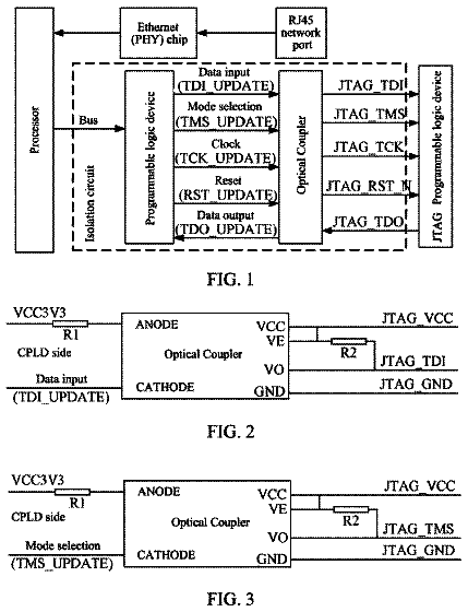
JTAG apparatus and method for implementing JTAG data transmission
A Joint Test Action Group (JTAG) apparatus and a method for implementing JTAG data transmission are disclosed.
US 8,689,090 B2 · Assignee: Samsung Electronics Co., Ltd. · Inventors: Myung; Se-Ho et al.
Sheet 1 of 7 from the published document. All sheets in the USPTO PDF
Methods and apparatuses are provided for achieving maximum diversity gain through channel coding based on a Low-Density Parity-Check (LDPC) code in a multiple antenna communication system. A method includes determining a parity-check matrix; generating a codeword using the parity-check matrix; puncturing a part of an information word; dividing a parity into a plurality of partial parities based on a number of transmit antennas; transmitting an unpunctured part of the information word and a partial parity over a first antenna; and transmitting at least one other partial parity over at least one other transmit antenna.
In a communication system, noises, fading, and Inter-Symbol Interference (ISI) of a channel distort a signal being transmitted. Particularly, in high-speed digital communication systems, such as advanced mobile communication, digital broadcasting, and mobile Internet, requiring high data throughput and high reliability, it is important to overcome signal distortion caused by noise, fading, and ISI. Channel coding and interleaving are some of the techniques for overcoming signal distortion. Specifically, interleaving is used to prevent burst errors that frequently occur during channel fading, to minimize data transmission loss, and to enhance a channel coding effect, by distributing errors of transmitted bits over multiple points. The channel coding is often used to enhance communication reliability in that a receiving node can confirm signal distortion caused by noise, fading, and ISI, a
All 7 drawing sheets from the published document, cropped to the drawing.
What the patent claimed, word for word. All of it is now free to use.
The present application claims priority under 35 U.S.C. .sctn.119(a) to Korean patent application Serial No. 10-2011-0000238, which was filed in the Korean Intellectual Property Office on Jan. 3, 2011, the entire content of which is incorporated herein by reference.
The present invention relates generally to a multiple antenna communication system, and more particularly, to an apparatus and a method for channel encoding and decoding a codeword based on a Low-Density Parity-Check (LDPC) code applying puncturing in the multiple antenna communication system.
In a communication system, noises, fading, and Inter-Symbol Interference (ISI) of a channel distort a signal being transmitted. Particularly, in high-speed digital communication systems, such as advanced mobile communication, digital broadcasting, and mobile Internet, requiring high data throughput and high reliability, it is important to overcome signal distortion caused by noise, fading, and ISI. Channel coding and interleaving are some of the techniques for overcoming signal distortion.
Specifically, interleaving is used to prevent burst errors that frequently occur during channel fading, to minimize data transmission loss, and to enhance a channel coding effect, by distributing errors of transmitted bits over multiple points.
The channel coding is often used to enhance communication reliability in that a receiving node can confirm signal distortion caused by noise, fading, and ISI, and efficiently recover the original signal. Codes used in channel coding are often referred to as "Error-Correcting Codes (ECC)".
Conventional ECCs include a parity-check code based on a parity-check matrix. The parity-check code can be defined using a parity-check matrix or a generator matrix. Basically, the parity-check matrix H or the generator matrix G of the parity-check code is given, and a codeword is determined to satisfy a relation as shown in Equation (1). mG=c Hc.sup.T=0
In Equation (1), m denotes an information word of a length K including K-ary information bits, and (m.sub.0, m.sub.1, . . . , m.sub.K-1). H denotes the parity-check matrix, G denotes the generator matrix, and c denotes a codeword obtained from the information word.
When the parity-check matrix is systematic, the codeword c is expressed as (m, p), where p denotes the parity. In general, when a message i.e., an information word) length is K and the codeword length is N, the parity length p is (N-K). With full rank, the size of the parity-check matrix is (N-K).times.N.
As for the systematic coding, the parity-check matrix as shown in Equation
is possible.
In Equation (2), H denotes the parity-check matrix.
The codeword c corresponding to the parity-check matrix of Equation
includes the information word m=(m.sub.0, m.sub.1, m.sub.2, m.sub.3) including four information bits, and the parity p=(p.sub.0, p.sub.1, p.sub.2, p.sub.3, p.sub.4) including five parity bits. The relationship of the codeword c and the parity-check matrix H is shown in Equation (3).
In Equation (3), H denotes the parity-check matrix, c denotes the codeword, m.sub.i denotes the information bit, and p.sub.i denotes the parity bit.
In the matrix of Equation (3), each row of the parity-check matrix represents an algebraic relational expression. Typically, an algebraic relational expression is referred to as a parity-check equation. Based on Equation (3), the algebraic relational expression is given by Equation (4).
.times. ##EQU00003##
In Equation (4), m.sub.i denotes the information bit and p.sub.i denotes the parity bit.
A nonzero element in the parity-check matrix is referred to as a weight. In general, as the number of the weights increases in the parity-check code, the encoding and decoding complexity rises. That is, the fewer weights in the parity-check matrix, the lower complexity. A code with few weights is referred to as a Low-Density Parity-Check (LDPC) code. In many cases, as the codeword of the LDPC code is lengthened, the weight density lowers.
When the systematic parity-check code is applied to a space-time code, which is a type of multiple antenna system, diversity can occur according to characteristics of the parity-check matrix. The diversity improves the signal quality of each antenna stream by reducing interference between the multiple antennas. As the diversity increases, a higher data rate can be provided.
When an LDPC code is used, the maximum diversity can depend on the characteristics of the parity-check matrix and the transmit antenna for transmitting the codeword. More specifically, a condition of the parity-check matrix for achieving the maximum diversity varies according to whether the parity-check matrix is systematic, and according to the number of the transmit antennas. Accordingly, to achieve maximum diversity using an LDPC in a multiple antenna communication system, it is necessary to define the condition of the parity-check matrix and the distribution criterion of the codeword per transmit antenna.
The present invention is designed to substantially solve at least the above-described problems and/or disadvantages and to provide at least the advantages below.
Accordingly, an aspect of the present invention is to provide an apparatus and a method for achieving maximum diversity in a space-time code using an LDPC code in a multiple antenna communication system.
Another aspect of the present invention is to provide an apparatus and a method for encoding and decoding using a parity-check matrix that satisfies a condition for maximum diversity in a multiple antenna communication system.
Another aspect of the present invention is to provide an apparatus and a method for transmitting a codeword over a plurality of transmit antennas based on a codeword distribution manner corresponding to a condition for maximum diversity in a multiple antenna communication system.
In accordance with an aspect of the present invention, an operating method of a transmitting node in a multiple-input multiple-output wireless communication system is provided. The method includes determining a parity-check matrix; generating a codeword using the parity-check matrix; puncturing a part of an information word; dividing a parity into a plurality of partial parities based on a number of transmit antennas; transmitting an unpunctured part of the information word and a partial parity over a first antenna; and transmitting at least one other partial parity over at least one other transmit antenna.
In accordance with another aspect of the present invention, an operating method of a receiving node in a multiple-input multiple-output wireless communication system is provided. The method includes receiving a codeword with part of an information word punctured therefrom, over a receive antenna; obtaining an unpunctured part of the information word and a partial parity from the codeword transmitted over a first transmit antenna of a transmitting node; obtaining at least one other partial parity from part of the codeword transmitted over at least one other transmit antenna; rearranging the unpunctured part of the information word and the partial parities; and restoring the information word by decoding the rearranged codeword using a parity-check matrix used by the transmitting node.
In accordance with another aspect of the present invention, an apparatus of a transmitting node in a multiple-input multiple-output wireless communication system is provided. The apparatus includes a controller for determining a parity-check matrix; an encoder for generating a codeword using the parity-check matrix; a puncturing unit for puncturing part of an information word; a distributor for dividing a parity into partial parities based on a number of transmit antennas; and a transmitter for transmitting an unpunctured part of the information word and a partial parity over a first antenna, and transmitting at least one other partial parity over at least one other transmit antenna.
In accordance with another aspect of the present invention, an apparatus of a receiving node in a multiple-input multiple-output wireless communication system is provided. The apparatus includes a receiver for receiving a codeword with part of an information word punctured therefrom, over a receive antenna; an arranger for obtaining an unpunctured part of the information word and a partial parity from the codeword transmitted over a first transmit antenna of a transmitting node, obtaining at least one other partial parity from part of the codeword transmitted over at least one other transmit antenna, and rearranging the unpunctured part of the information word and the partial parities; and a decoder for restoring the information word by decoding the rearranged codeword using a parity-check matrix used by the transmitting node.
The above and other aspects, features, and advantages of certain embodiments of the present invention will be more apparent from the following detailed description taken in conjunction with the accompanying drawings, in which:
FIG. 1 illustrates codeword transmission in a multiple antenna communication system according to an embodiment of the present invention;
FIG. 2 illustrates a transmission of a punctured codeword over two transmit antennas in a multiple antenna communication system according to an embodiment of the present invention;
FIG. 3 illustrates a transmission of a punctured codeword over three transmit antennas in a multiple antenna communication system according to an embodiment of the present invention;
FIG. 4 is a flow chart illustrating an operation of a transmitting node in a multiple antenna communication system according to an embodiment of the present invention;
FIG. 5 is a flow chart illustrating an operation of a receiving node in a multiple antenna communication system according to an embodiment of the present invention;
FIG. 6 is a block diagram illustrating a transmitting node in a multiple antenna communication system according to an embodiment of the present invention; and
FIG. 7 is a block diagram illustrating a receiving node in a multiple antenna communication system according to an embodiment of the present invention.
Throughout the drawings, like reference numerals will be understood to refer to like parts, components, and structures.
Various embodiments of the present invention will be described is detail herein below with reference to the accompanying drawings. In the following description, well-known functions or constructions are not described in detail to avoid obscuring the present invention in unnecessary detail.
In accordance with an embodiment of the present invention, a technique for achieving maximum diversity through space-time coding using an LDPC code in a multiple antenna communication system is provided.
When a transmitting node including two transmit antennas performs space-time coding using a systematic parity-check matrix, diversity can be achieved based on a condition as described below.
A parity-check matrix of a systematic parity-check code can be given by Equation (5).
.times..times..times..times..times..times. .times..times. ##EQU00004##
In Equation (5), H.sub.A denotes the parity-check matrix, H.sub.I denotes a submatrix corresponding to an information word, and H.sub.P denotes a submatrix corresponding to a parity.
Based on Equation (5), when an information word length is K and a codeword length is N, the size of the submatrix H.sub.I corresponding to the information word is (N-K).times.K and the size of the submatrix H.sub.P corresponding to the parity is (N-K).times.(N-K). Because the codeword satisfies the relationship shown in Equation (1), the relational expression of Equation
is valid.
.function..times..revreaction..times..revreaction..times. ##EQU00005##
In Equation (6), H.sub.A denotes the parity-check matrix, c denotes the codeword, H.sub.I denotes the submatrix corresponding to the information word, H.sub.P denotes the submatrix corresponding to the parity, in denotes the information word, and p denotes the parity.
FIG. 1 illustrates codeword transmission in a multiple antenna communication system according to an embodiment of the present invention.
Referring to FIG. 1, the codeword c=(m, p) is transmitted through two antennas. Specifically, in the codeword c=(m, p), which is generated from the parity-check matrix H.sub.A, the information word m is transmitted via a first transmit antenna and the parity p is transmitted via a second transmit antenna. To attain maximum diversity, when a 2.times.K-sized matrix
##EQU00006## corresponding to a random codeword c=(m, p) excluding zero codewords is given, the matrix C should have full rank all the time. For example, the rank of an m.times.n matrix cannot be greater than m nor n. Further, a matrix that has a rank as large as possible is said to have full rank. Herein, the full rank implies that the same row as a particular row is not derived even by subtracting or adding at least two of the rows of the corresponding matrix.
Accordingly, because the matrix C is in the size of 2.times.K, full rank of the matrix C is 2. Thus, when searching for a parity-check code that satisfies the condition for achieving maximum diversity, a receiving node using two transmit antennas has the same problem as designing the parity-check matrix in which the rank of the matrix C is not 1 with respect to a random codeword excluding the zero codewords.
Cases where the rank of the matrix C is 1 and conditions of the parity-check matrix H.sub.A for avoiding the corresponding cases are shown in Table 1.
TABLE-US-00001 TABLE 1 Condition of H.sub.A to avoid case Case where rank is 1 where rank is 1 m .noteq. p, p = 0 H.sub.I has the full rank. m = p, p .noteq. 0 H.sub.P has the full rank. m = p .noteq. 0 H.sub.I + H.sub.P has the full rank.
Based on Table 1, in the first case for rank 1, in is not zero and p is zero. When H.sub.I has full rank, m.sup.T=H.sub.I.sup.1H.sub.Pp.sup.T is derived from Equation (6). When the parity matrix p is zero, the information word in is also zero. Therefore, the first case for rank 1 in Table 1 is not valid.
In the second case for rank 1, in is zero and p is not zero. When H.sub.P has full rank, p.sup.T=H.sub.P.sup.1H.sub.Im.sup.T is derived from Equation (6). When the information word in is zero, the parity matrix p is also zero. Therefore, the second case for rank 1 in Table 1 is not valid.
In the third case for rank 1, m and p are equal and neither is zero. When m and p are equal and H.sub.I+H.sub.P has full rank, 0=H.sub.Im.sup.T+H.sub.Pp.sup.T=(H.sub.I+H.sub.P)m.sup.T is derived from Equation (6). When H.sub.I+H.sub.P has full rank, in and p are zero. Therefore, the third case for rank 1 in Table 1 is also not valid.
When satisfying all of the conditions for avoiding the rank 1 in Table 1, the transmitting node can attain the maximum diversity.
Besides the parity-check matrix shown in Equation (5), a system according to an embodiment of the present invention can use a parity-check matrix as shown in Equation (7).
.times..times. .times..times..times..times..times..times..times..times..times..times. .times..times..times..times..times..times..times..times..times. .times..times. ##EQU00007##
In Equation (7), H.sub.B denotes the parity-check matrix, H.sub.I1, H.sub.I2, and H.sub.I3 denote the submatrices corresponding to the information word, and H.sub.P1 and H.sub.P2 denote the submatrices corresponding to the parity. Among the submatrices corresponding to the information word, H.sub.I1 and H.sub.I2 are the submatrices corresponding to the untransmitted information word. That is, H.sub.I1 and H.sub.I2 correspond to the punctured codeword.
The parity-check matrix shown in Equation
can be decomposed, where
.times..times..times..times. ##EQU00008## is a submatrix corresponding to part m.sub.1 of the information word in a length K.sub.1,
.times..times. ##EQU00009## is a submatrix corresponding to part m.sub.2 of the information word in a length K.sub.2,
.times..times. ##EQU00010## is a submatrix corresponding to part p of the parity in a length (K.sub.1+K.sub.2), and
.times..times. ##EQU00011## is a submatrix corresponding to part p.sub.2 of the information word in a length K.sub.1. Accordingly, the length of the information word (m.sub.1, m.sub.2) is (K.sub.1+K.sub.2) and the length of the parity (p.sub.1, p.sub.2) is (2K.sub.1+K.sub.2). The size of H.sub.I1 is K.sub.1.times.K.sub.1, the size of H.sub.I2 is K.sub.1.times.K.sub.1, the size of H.sub.I3 is (K.sub.1+K.sub.2).times.K.sub.2, the size of H.sub.P1 is (K.sub.1+K.sub.2).times.(K.sub.1+K.sub.2), and the size of H.sub.P2 is K.sub.1.times.K.sub.1.
Because the codeword c=(m.sub.1, m.sub.2, p.sub.1, p.sub.2) satisfies H.sub.Bc.sup.T=0, a relational expression shown in Equation
is established.
.times..times..times..times..times..times..times..times..times..times. ##EQU00012##
In Equation (8), H.sub.B denotes the parity-check matrix, c denotes the codeword, H.sub.I1, H.sub.I2, and H.sub.I3 denote the submatrices corresponding to the information word, H.sub.P1 and H.sub.P2 denote the submatrices corresponding to the parity, m.sub.i denotes part of the information word, and p.sub.i denotes part of the parity.
Equation
can be arranged as shown in Equation (9). H.sub.I1m.sub.1.sup.T+H.sub.I3m.sub.2.sup.T+H.sub.P1p.sub.1.sup.T=0 H.sub.I2m.sub.1.sup.T+H.sub.P2p.sub.2.sup.T=0
In Equation (9), H.sub.I1, H.sub.I2, and H.sub.I3 denote the submatrices corresponding to the information word, H.sub.P1 and H.sub.P2 denote the submatrices corresponding to the parity, m.sub.i denotes part of the information word, and p.sub.i denotes part of the parity.
In the communication system using the parity-check code or the LDPC code corresponding to the parity-check matrix H.sub.B of Equation (7), the transmitting node may puncture, i.e., not transmit, part m.sub.i of the information word of the length K.sub.1 in the codeword c=(m.sub.1, m.sub.2, p.sub.1, p.sub.2).
FIG. 2 illustrates a transmission of a punctured codeword over two transmit antennas in a multiple antenna communication system according to an embodiment of the present invention.
Referring to FIG. 2, the transmitting node transmits the punctured codeword c'=(m.sub.2, p.sub.1, p.sub.2), where (p.sub.2, m.sub.2) is transmitted over the first transmit antenna and p.sub.1 is transmitted over the second transmit antenna. Accordingly, the transmitting node transmits p.sub.2 first and then m.sub.2 over the first transmit antenna. Because the initial information word length is (K.sub.1+K.sub.2) and the length of the punctured codeword c'=(m.sub.2, p.sub.1, p.sub.2) actually transmitted is 2(K.sub.1+K.sub.2), the actual code rate is 1/2. The lengths of (p.sub.2, m.sub.2) transmitted over the first transmit antenna and p.sub.1 transmitted over the second transmit antenna are equal to (K.sub.1+K.sub.2).
A condition for attaining maximum diversity in a transmitting node using two transmit antennas will be described below, where the parity-check matrix shown in Equation
is used.
A certain punctured codeword c'=(m.sub.2, p.sub.1, p.sub.2), excluding the zero codewords, can be expressed as a matrix
##EQU00013## in the size 2.times.(K.sub.1+K.sub.2), and the matrix
##EQU00014## should have full rank. Given the two transmit antennas, the full rank of the matrix
##EQU00015## is 2. Therefore, when the parity-check matrix as shown in Equation
is used, determining the parity-check code satisfying the condition for achieving the maximum diversity in the transmitting node using the two transmit antennas is the same problem as designing the parity-check matrix such that the rank of the matrix
##EQU00016## is not zero with respect to a random codeword excluding the zero codewords.
When m.sub.1.sup.T=H.sub.I2.sup.1H.sub.P2p.sub.2.sup.T is derived from the lower equation of Equation
and is applied to the upper equation of Equation (9), H.sub.I1+H.sub.I2.sup.-1H.sub.P2p.sub.2.sup.T+H.sub.I3m.sub.2.sup.T+H.sub- .P1p.sub.1.sup.T=0 is derived. The condition of the parity-check matrix H.sub.B for blocking the rank of the matrix
##EQU00017## from being 1 is derived from H.sub.I1+H.sub.I2.sup.-1H.sub.P2p.sub.2.sup.T+H.sub.I3m.sub.2.sup.T+H.sub- .P1p.sub.1.sup.T=0 as shown below.
More specifically, when (p.sub.2, m.sub.2) is substituted with one vector v, H.sub.I1+H.sub.I2.sup.-1H.sub.P2p.sub.2.sup.T+H.sub.I3m.sub.2.sup.T+H.- sub.P1p.sub.1.sup.T=0 is expressed as shown in Equation (10). [H.sub.I1H.sub.I2.sup.-1H.sub.P2H.sub.I3]v.sup.T+H.sub.P1p.sub.1.sup.T=0
In Equation (10), H.sub.I1, H.sub.I2, and H.sub.I3 denote the submatrices corresponding to the information word, H.sub.P1 and H.sub.P2 denote the submatrices corresponding to the parity, v denotes (p.sub.2, m.sub.2), m.sub.i denotes part of the information word, and p.sub.i denotes part of the parity.
In the first case for rank 1, v is not zero and p.sub.1 is zero. Yet, when [H.sub.I1H.sub.I2.sup.-1H.sub.P2H.sub.I3] of Equation
has the full rank and an inverse matrix, v.sup.T=[H.sub.I1H.sub.I2.sup.-1H.sub.P2H.sub.I3].sup.-1H.sub.P1p.sub.1.s- up.T is satisfied. At this time, the case where v is not zero and p.sub.1 is zero cannot be established.
In the second case for rank 1, v is zero and p.sub.1 is not zero. However, when H.sub.P1 of Equation
has full rank and an inverse matrix, p.sub.1.sup.T=H.sub.P1.sup.-1[H.sub.I1H.sub.I2.sup.-1H.sub.P2H.su- b.I3].sup.-1v.sup.T is satisfied. At this time, the case where v is zero and p.sub.1 is not zero also cannot be established.
In the third case for rank 1, v and p.sub.1 are equal and neither is zero. However, when [H.sub.I1H.sub.I2.sup.-1H.sub.P2H.sub.I3]+H.sub.P1 of Equation
has full rank, 0=[H.sub.I1H.sub.I2.sup.-1H.sub.P2H.sub.I3]v.sup.T+H.sub.P1p.sub.1.sup.T=- ([H.sub.I1H.sub.I2.sup.-1H.sub.P2H.sub.I3]+H.sub.P1)v.sup.T is satisfied. At this time, the case where v and p.sub.1 are equal and neither is zero cannot be established.
In the communication system using the parity-check code corresponding to the parity-check matrix H.sub.B as shown in Equation (7), the condition of the transmitting node that punctures part m.sub.1 of the K.sub.1-length information word of the codeword c=(m.sub.1, m.sub.2, p.sub.1, p.sub.2) and transmits (p.sub.2, m.sub.2) over the first transmit antenna and p.sub.1 over the second transmit antenna, for attaining maximum diversity is as explained above. This condition is shown below in Table 2.
TABLE-US-00002 TABLE 2 Condition of H.sub.B to avoid case where rank is 1 Case where rank is 1 (v = (p.sub.2, m.sub.2)) v .noteq. p.sub.1, p.sub.1 = 0 [H.sub.I1 + H.sub.I2.sup.-1 H.sub.P2 H.sub.I3] has the full rank. v = p.sub.1 , p.sub.1 .noteq. 0 H.sub.P1 has the full rank. v = p.sub.1 .noteq. 0 [H.sub.I1 + H.sub.I2.sup.-1 H.sub.P2 H.sub.I3] + H.sub.P1 has the full rank.
When satisfying all of the conditions for avoiding rank 1 in Table 2, the transmitting node can achieve maximum diversity.
In addition the parity-check matrix of Equation
or Equation (7), the system can use a parity-check matrix as shown in Equation
using three transmit antennas.
.times..times. .times..times..times..times..times..times..times..times..times..times. .times..times..times..times..times..times..times..times..times..times. .times..times. ##EQU00018##
In Equation (11), H.sub.C denotes the parity-check matrix, H.sub.I1, H.sub.I2, and H.sub.I3 denote the submatrices corresponding to the information word, and H.sub.P1, H.sub.P2 and H.sub.P3 denote the submatrices corresponding to the parity. Among the submatrices corresponding to the information word, H.sub.I1 and H.sub.I2 are the submatrices corresponding to the untransmitted information word, i.e., correspond to the punctured codeword.
The parity-check matrix as shown in Equation
can be decomposed, where
.times..times..times..times. ##EQU00019## is a submatrix corresponding to part m.sub.1 of a K.sub.1-length information word,
.times..times. ##EQU00020## is a submatrix corresponding to part m.sub.2 of a K.sub.2-length information word,
.times..times. ##EQU00021## is a submatrix corresponding to part p.sub.1 of a (K.sub.1+K.sub.2)-length parity,
.times..times. ##EQU00022## is a submatrix corresponding to part p.sub.2 of a K.sub.1-length information word, and
.times..times. ##EQU00023## is a submatrix corresponding to part p.sub.3 of a K.sub.1-length information word. Accordingly, the length of the information word (m.sub.1, m.sub.2) is (K.sub.1+K.sub.2) and the length of the parity (p.sub.1, p.sub.2, p.sub.3) is (3K.sub.1+2K.sub.2). The size of H.sub.I1 is (2K.sub.1.times.2K.sub.1).times.K.sub.1, the size of H.sub.I2 is K.sub.1.times.K.sub.1, the size of H.sub.I3 is (2K.sub.1+2K.sub.2).times.K.sub.2, the size of H.sub.P1 and H.sub.P2 is (2K.sub.1+2K.sub.2).times.(K.sub.1+K.sub.2), and the size H.sub.P3 of is K.sub.1.times.K.sub.1.
Because the codeword c=(m.sub.1, m.sub.2, p.sub.1, p.sub.2, p.sub.3) satisfies H.sub.Cc.sup.T=0, Equation
is valid.
.times..times..times..times..times..times..times..times..times..times..ti- mes..times. ##EQU00024##
In Equation (12), H.sub.C denotes the parity-check matrix, c denotes the codeword, H.sub.I1, H.sub.I2, and H.sub.I3 denote the submatrices corresponding to the information word, H.sub.P1, H.sub.P2 and H.sub.P3 denote the submatrices corresponding to the parity, in denotes part of the information word, and p.sub.i denotes part of the parity.
Equation
can be arranged as shown in Equation (13). H.sub.I1m.sub.1.sup.T+H.sub.I3m.sub.2.sup.T+H.sub.P1p.sub.1.sup.T+H.sub.P- 2p.sub.2.sup.T=0 H.sub.I2m.sub.1.sup.T+H.sub.P3p.sub.3.sup.T=0
In Equation (13), H.sub.I1, H.sub.I2, and H.sub.I3 denote the submatrices corresponding to the information word, H.sub.P1, H.sub.P2 and H.sub.P3 denote the submatrices corresponding to the parity, in denotes part of the information word, and p.sub.i denotes part of the parity.
In the communication system using the parity-check code or the LDPC code corresponding to the parity-check matrix H.sub.C of Equation (11), the transmitting node may puncture, i.e., not transmit, the part m.sub.1 of the K.sub.1-length information word in the codeword c=(m.sub.1, m.sub.2, p.sub.1, p.sub.2, p.sub.3).
FIG. 3 illustrates a transmission of a punctured codeword over three transmit antennas in a multiple antenna communication system according to an embodiment of the present invention.
Referring to FIG. 3, the transmitting node transmits the punctured codeword c'=(m.sub.2, p.sub.1, p.sub.2, p.sub.3), where (p.sub.3, m.sub.2) are transmitted over the first transmit antenna, p.sub.1 is transmitted over the second transmit antenna, and p.sub.2 is transmitted over the third transmit antenna. Accordingly, the transmitting node first transmits p.sub.3 and then transmits m.sub.2 over the first transmit antenna. Because the initial information word length is 9(K.sub.1+K.sub.2) and the length of the punctured codeword c'=(m.sub.2, p.sub.1, p.sub.2, p.sub.3) actually transmitted is 3(K.sub.1+K.sub.2), the actual code rate is 1/3. The lengths of (p.sub.3, m.sub.2) transmitted over the first transmit antenna, p.sub.1 transmitted over the second transmit antenna, and p.sub.2 transmitted over the third transmit antenna are equal to (K.sub.1+K.sub.2).
A condition for attaining maximum diversity in a transmitting node using three transmit antennas is described below, when the parity-check matrix of Equation
is used.
A random punctured codeword c'=(m.sub.2, p.sub.1, p.sub.2, p.sub.3), excluding the zero codewords, can be expressed as a matrix
##EQU00025## in the size 3.times.(K.sub.1+K.sub.2), and the matrix
##EQU00026## should have the full rank. Given the three transmit antennas, the full rank of the matrix
##EQU00027## is 3. Accordingly, when the parity-check matrix of Equation
is used, determining a parity-check code that satisfies the condition for achieving maximum diversity in the transmitting node using the three transmit antennas is the same problem as the designing the parity-check matrix such that the rank of the matrix
##EQU00028## is not 1 or 2 with respect to a random codeword excluding the zero codewords.
When m.sub.1.sup.T=H.sub.I2.sup.-1H.sub.P3p.sub.3.sup.T is derived from the lower equation shown in Equation
and is applied to the upper equation shown in Equation (13), H.sub.I1+H.sub.I2.sup.-1H.sub.P3p.sub.3.sup.T+H.sub.I3m.sub.2.sup.T+H.sub- .P1p.sub.1.sup.T+P.sub.P2p.sub.2.sup.T=0 is derived. The condition of the parity-check matrix H.sub.C for preventing the rank of the matrix
##EQU00029## from being 1 or 2 is derived from H.sub.I1+H.sub.I2.sup.-1H.sub.P3p.sub.3.sup.T+H.sub.I3m.sub.2.sup.T+H.sub- .P1p.sub.1.sup.T+P.sub.P2p.sub.2.sup.T=0 as will be described below.
More specifically, when (p.sub.3, m.sub.2) is substituted with one vector v, H.sub.I1+H.sub.I2.sup.-1H.sub.P2p.sub.2.sup.T+H.sub.I3m.sub.2.sup.T+H.- sub.P1p.sub.1.sup.T=0 is arranged as shown in Equation (14). [H.sub.I1H.sub.I2.sup.-1H.sub.P2H.sub.I3]v.sup.T+H.sub.P1p.sub.1.sup.T+H.- sub.P2p.sub.2.sup.T=0
In Equation (14), H.sub.I1, H.sub.I2, and H.sub.I3 denote the submatrices corresponding to the information word, H.sub.P1, H.sub.P2 and H.sub.P3 denote the submatrices corresponding to the parity, v denotes (p.sub.3, m.sub.2), denotes part of the information word, and p.sub.i denotes part of the parity.
The rank 1 is achieved as follows.
In a first case, where v is not zero and both of p.sub.1 and p.sub.2 is zero, the rank is 1.
In a second case, where p.sub.1 is not zero and both of p.sub.2 and v is zero, the rank is 1.
In a third case, where p.sub.2 is not zero and both of v and p.sub.1 is zero, the rank is 1.
In a fourth case, where v and p.sub.1 are equal and neither is zero and p.sub.2 is zero, the rank is 1.
In a fifth case, where v and p.sub.2 are equal and neither is zero and p.sub.1 is zero, the rank is 1.
In a sixth case, where p.sub.1 and p.sub.2 are equal and neither is zero and v is zero, the rank is 1.
In a seventh case, where all of v, p.sub.1 and p.sub.2 are equal and neither is zero, the rank is 1.
When [H.sub.I1H.sub.I2.sup.-1H.sub.P3H.sub.I3] has full rank, the first case cannot be established. When H.sub.P1 has full rank, the second case cannot be established. When H.sub.P2 has full rank, the third case cannot be established. When [H.sub.I1H.sub.I2.sup.-1H.sub.P3H.sub.I3]+H.sub.P1 has full rank, the fourth case cannot be established. When [H.sub.I1H.sub.I2.sup.-1H.sub.P3H.sub.I3]+H.sub.P2 has full rank, the fifth case cannot be established. When H.sub.P1+H.sub.P2 has full rank, the sixth case cannot be established. When [H.sub.I1H.sub.I2.sup.-1H.sub.P3H.sub.I3]+H.sub.P1+H.sub.P2 has full rank, the seventh case cannot be established.
The rank 2 is achieved as follows.
In a first case, where v and p.sub.1 are not zero and p.sub.2 is zero, the rank is 2.
In a second case, where v and p.sub.2 are not zero and p.sub.1 is zero, the rank is 2.
In a third case, where p.sub.1 and p.sub.2 are not zero and v is zero, the rank is 2.
In a fourth case, where v and p.sub.1 are not zero and p.sub.2 and v are equal, the rank is 2.
In a fifth case, where v and p.sub.2 are not zero and p.sub.1 and p.sub.2 are equal, the rank is 2.
In a sixth case, where p.sub.1 and p.sub.2 are not zero and v and p.sub.1 are equal, the rank is 2.
In a seventh case, where v and p.sub.1 are not zero and p.sub.2 and v+p.sub.1 are equal, the rank is 2.
When [H.sub.I1H.sub.I2.sup.-1H.sub.P3H.sub.I3H.sub.P1] has full rank, the first case cannot be established. When [H.sub.I1H.sub.I2.sup.-1H.sub.P3H.sub.I3H.sub.P2] has full rank, the second case cannot be established. When [H.sub.P1H.sub.P2] has full rank, the third case cannot be established. When [([H.sub.I1H.sub.I2.sup.-1H.sub.P3H.sub.I3]+H.sub.P2)H.sub.P1] has full rank, the fourth case cannot be established. When [[H.sub.I1H.sub.I2.sup.-1H.sub.P3H.sub.I3](H.sub.P2+H.sub.P1)] has full rank, the fifth case cannot be established. When [([H.sub.I1H.sub.I2.sup.-1H.sub.P3H.sub.I3]+H.sub.P1)H.sub.P2] has full rank, the sixth case cannot be established. When [([H.sub.I1H.sub.I2.sup.-1H.sub.P3H.sub.I3]+H.sub.P1)([H.sub.I1H.sub.I2.s- up.-1H.sub.P3H.sub.I3]+H.sub.P2)] has full rank, the seventh case cannot be established.
In the communication system using the parity-check code corresponding to the parity-check matrix H.sub.C of Equation (11), the condition of the transmitting node that punctures part m.sub.1 of the K.sub.1-length information word of the codeword c=(m.sub.1, m.sub.2, p.sub.1, p.sub.2, p.sub.3) and transmits (p.sub.3, m.sub.2) over the first transmit antenna, p.sub.1 over the second transmit antenna, and p.sub.2 over the third transmit antenna for attaining maximum diversity is as described above. More specifically, this condition is shown in Table 3.
TABLE-US-00003 TABLE 3 Condition of H.sub.C to avoid case where rank is 1 Case where rank is 1 (v = ( p.sub.3, m.sub.2), H.sub.X = R.sub.I1H.sub.I2.sup.-1H.sub.P3) v .noteq. 0, p.sub.1 = p.sub.2 = 0 [H.sub.X H.sub.I3] has the full rank. p.sub.1 .noteq. 0, v = p.sub.2 = 0 H.sub.P1 has the full rank. p.sub.2 .noteq. 0, v = p.sub.1 = 0 H.sub.P2 has the full rank. v = p.sub.1 .noteq. 0, p.sub.2 = 0 [H.sub.X H.sub.I3] + H.sub.P1 has the full rank. v = p.sub.2 .noteq. 0, p.sub.1 = 0 [H.sub.X H.sub.I3] + H.sub.P2 has the full rank. p.sub.1 = p.sub.2 .noteq. 0, v = 0 H.sub.P1 + H.sub.P2 has the full rank. v = p.sub.1 = p.sub.2 .+-. 0 [H.sub.X H.sub.I3] + H.sub.P1 + H.sub.P2 has the full rank. Condition of H.sub.C to avoid case where rank is 2 Case where rank is 2 (v = (p.sub.3 , m.sub.2), H.sub.X = H.sub.I1H.sub.I2.sup.-1H.sub.P3) v .noteq. 0, p.sub.1 .noteq. 0, p.sub.2 = 0 [H.sub.X H.sub.I3 H.sub.P1] has the full rank. v .noteq. 0 , p.sub.2 .noteq. 0, p.sub.1 = 0 [H.sub.X H.sub.I3 H.sub.P2] has the full rank. p.sub.1 .noteq. 0, p.sub.2 .noteq. 0, v = 0 [H.sub.P1 H.sub.P2] has the full rank. v .noteq. 0, p.sub.1 .noteq. 0, p.sub.2 = v [([H.sub.X H.sub.I3] + H.sub.P2) H.sub.P1] has the full rank. v .noteq. 0, p.sub.2 .noteq. 0, p.sub.1 = p.sub.2 [([H.sub.X H.sub.I3] (H.sub.P1 + H.sub.P2)] has the full rank. p.sub.1 .noteq. 0, p.sub.2 .noteq. 0, v = p.sub.1 [([H.sub.X H.sub.I3] + H.sub.P1) H.sub.P2] has the full rank. v .noteq. 0, p.sub.1 .noteq. 0, p.sub.2 = v + p.sub.1 [([H.sub.X H.sub.I3] + H.sub.P1) ([H.sub.X H.sub.I3] + H.sub.P2)] has the full rank.
When satisfying all of the conditions for avoiding the rank 1 and all of the conditions for avoiding the rank 2 in Table 3, the transmitting node can achieve maximum diversity.
As described above, when the parity-check matrix is given, the conditions for attaining maximum diversity can be derived. The condition derivation can be similarly applied to four or more transmit antennas. That is, when one transmit antenna transmits part of the parity and the unpunctured information word, and other transmit antennas transmit the remaining parities in a same length as the length of the parity and the information word transmitted over the one transmit antenna, the conditions of the corresponding parity-check matrix can be derived similarly to the above-described condition derivation.
For example, with respect to the codeword c=(m.sub.1, m.sub.2, p.sub.1, p.sub.2, . . . p.sub.M-1, p.sub.M) including zeros, when the transmitting node applying a space-time code using M-ary transmit antennas punctures m.sub.1, transmits (p.sub.M, m.sub.2) over the first transmit antenna, and transmits p.sub.1, p.sub.2, . . . p.sub.M-1 over the other (M-1)-ary transmit antennas, the transmitting node can achieve the maximum diversity by designing the parity-check matrix such that
##EQU00030## has full rank.
FIG. 4 is a flow chart illustrating an operation of a transmitting node in a multiple antenna communication system according to an embodiment of the present invention.
Referring to FIG. 4, the transmitting node performs LDPC encoding using a parity-check matrix in step 401. More specifically, the transmitting node determines the parity-check matrix according to the code rate defined in the system, the length of the codeword, the length of the information word, and the number of the transmit antennas. The transmitting node generates or loads the determined parity-check matrix, and determines the parity that makes the product the parity-check matrix and a transpose matrix of the codeword zero.
For example, the transmitting node can use the parity-check matrix shown in Equation
or Equation (11). When the parity-check matrix shown in Equation
is used, at least one of [H.sub.I1H.sub.I2.sup.-1H.sub.P2H.sub.I3], H.sub.P1, and [H.sub.I1H.sub.I2.sup.-1H.sub.P2H.sub.I3]+H.sub.P1 of the parity-check matrix has full rank.
When the parity-check matrix shown in Equation
is used, at least one of [H.sub.I1H.sub.I2.sup.-1H.sub.P3H.sub.I3], H.sub.P1, H.sub.P2, [H.sub.I1H.sub.I2.sup.-1H.sub.P3H.sub.I3]+H.sub.P1, [H.sub.I1H.sub.I2.sup.-1H.sub.P3H.sub.I3]+H.sub.P2, H.sub.P1+H.sub.P2, [H.sub.I1H.sub.I2.sup.-1H.sub.P3H.sub.I3]+H.sub.P1+H.sub.P2, [H.sub.I1H.sub.I2.sup.-1H.sub.P3H.sub.I3H.sub.P1], [H.sub.I1H.sub.I2.sup.-1H.sub.P3H.sub.I3H.sub.P2], [H.sub.P1H.sub.P2][([H.sub.I1H.sub.I2.sup.-1H.sub.P3H.sub.I3]+H.sub.P2)H.- sub.P1], [[H.sub.I1H.sub.I2.sup.-1H.sub.P3H.sub.I3](H.sub.P2+H.sub.P1)], [([H.sub.I1H.sub.I2.sup.-1H.sub.P3H.sub.I3]+H.sub.P1)H.sub.P2], and [([H.sub.I1H.sub.I2.sup.-1H.sub.P3H.sub.I3]+H.sub.P1)([H.sub.I1H.sub.I2.s- up.-1H.sub.P3H.sub.I3]+H.sub.P2)] has full rank.
In step 403, the transmitting node punctures part of the codeword. Specifically, the transmitting node punctures part of the information word. For example, the transmitting node splits the information word to two partial information words, and punctures the first partial information word including a Most Significant Bit (MSB) of the codeword.
In step 405, the transmitting node divides the punctured codeword and distributes the divided codeword fragments to the transmit antennas. That is, the transmitting node divides the punctured partial codeword into the plurality of the fragments and distributes the fragments to the plurality of the transmit antennas.
For example, the transmitting node divides the parity into as many partial parities as there are transmit antennas, and distributes the other partial information word unpunctured and one partial parity to the first transmit antenna and the other partial parities to the remaining transmit antennas. Herein, the length of the other partial parity can equal the length of the other partial information word unpunctured and the one partial parity. The partial parity output to the first transmit antenna path together with the unpunctured information word includes a Least Significant Bit (LSB) of the codeword.
In step 407, the transmitting node transmits the punctured and distributed codeword over the plurality of the transmit antennas according to the distribution in step 405. That is, the transmitting node transmits the other partial information word unpunctured and the one partial parity over the first transmit antenna and transmits the other partial parities over the remaining transmit antennas. Accordingly, the transmitting node first transmits the one partial parity and then transmits the unpunctured information word over the first transmit antennas.
FIG. 5 is a flow chart illustrating an operation of a receiving node in a multiple antenna communication system according to an embodiment of the present invention.
Referring to FIG. 5, in step 501, the receiving node receives the codeword with part of the information word punctured, over at least one receive antenna.
The description continues in the full USPTO document.
About 5,706 words. The USPTO PDF has it with every drawing.
Fees are due 3.5, 7.5 and 11.5 years after grant. This patent expired on April 1, 2026, so the fee marked "not paid" was the one that went unpaid.
APPARATUS AND METHOD FOR CHANNEL ENCODING AND DECODING BASED ON LOW-DENSITY PARITY CHECK CODE IN MULTIPLE ANTENNA COMMUNICATION SYSTEM
Filed Dec 2011 · published Jul 2012Apparatus and method for channel encoding and decoding based on low-density parity check code in multiple antenna communication system
Filed Dec 2011 · granted Apr 2014Earlier publications, parents and continuations. None of them can still be enforced, or this patent would not be listed.
Prior art cited by the examiner or applicant. Useful when you check your own idea for novelty.
Everything on this page comes from the documents linked above.