Background
Heating, ventilating, and air conditioning (HVAC) systems often have dehumidification systems integrated into the cooling apparatus for dehumidifying the air being conditioned by such systems. When cooling is required in warm to hot environments, the air being cooled and dehumidified will usually have a humidity ratio above approximately 0.009 (pounds of H.sub.2O per pounds of dry air). In these environments, the HVAC systems traditionally use refrigerant compressors for sensible cooling of the air and removal of latent energy (i.e., humidity). The air is typically cooled to about 55.degree. F., which condenses H.sub.2O out of the air until the air is about 100% saturated (i.e., relative humidity at about 100%). The 55.degree. F. temperature lowers the humidity ratio to about 0.009 pounds of H.sub.2O per pounds of dry air, which is the water vapor saturation point at 55.degree. F., resulting in a relative humidity of almost 100%. When this air warms to about 75.degree. F., the humidity ratio remains approximately the same, and the relative humidity drops to approximately 50%. This traditional method of dehumidification requires the air to be cooled to about 55.degree. F., and can usually achieve a coefficient of performance (COP) of approximately 3-5.
Brief description
Certain embodiments commensurate in scope with the present disclosure are summarized in the following. These embodiments are not intended to limit the scope of the claimed invention, but rather these embodiments are intended only to provide a brief summary of possible forms of the invention. Indeed, the invention may encompass a variety of forms that may be similar to or different from the embodiments set forth in the following.
In a first embodiment, a dehumidification system for removing water vapor from an airstream is provided. The dehumidification system includes a plurality of dehumidification units. Each dehumidification unit includes a first and second channel separated by a membrane. The membrane is configured to facilitate removal of water vapor from an airstream flowing through the first channel by facilitating passage of H.sub.2O from the water vapor to the second channel through permeable volumes of the membrane while substantially blocking all other components of the airstream from passing through the membrane. The dehumidification system also includes at least one pressure increasing device configured to create a lower partial pressure of water vapor within the second channels than in the first channels, such that the H.sub.2O moves through the membranes to the second channels. The at least one pressure increasing device is also configured to increase the pressure of water vapor at an outlet of the at least one pressure increasing device to a partial pressure of water vapor in a range suitable for subsequent condensing into liquid water. The dehumidification system further includes at least one condensation device configured to receive the water vapor from the at least one pressure increasing device and condense the water vapor into liquid water. The dehumidification system also includes at least one water transport device configured to transport the liquid water from the at least one condensation device.
In a second embodiment, a system includes a dehumidification system for removing H.sub.2O vapor from an airstream. The dehumidification system includes a plurality of dehumidification units, each comprising an air channel configured to receive an inlet airstream and discharge an outlet airstream, and an H.sub.2O permeable barrier adjacent to the air channel. The H.sub.2O permeable barrier is configured to selectively enable H.sub.2O from H.sub.2O vapor in the inlet airstream to pass through the H.sub.2O permeable barrier to a suction side of the H.sub.2O permeable barrier and substantially block other components in the inlet airstream from passing through the H.sub.2O permeable barrier to the suction side of the H.sub.2O permeable barrier. The dehumidification system also includes at least one pressure increasing device configured to create a lower partial pressure of H.sub.2O vapor on the suction sides of the H.sub.2O permeable barriers than the partial pressure of the H.sub.2O vapor in the inlet airstreams to drive passage of the H.sub.2O from the H.sub.2O vapor in the inlet airstream through the H.sub.2O permeable barrier, and to increase the pressure at an outlet of the at least one pressure increasing device to a partial pressure of H.sub.2O vapor suitable for condensing H.sub.2O vapor into liquid H.sub.2O. The dehumidification system further includes at least one condensation device configured to receive the H.sub.2O vapor from the outlet of the at least one pressure increasing device, and to condense the H.sub.2O vapor into liquid H.sub.2O.
In a third embodiment, a method includes receiving a plurality of airstreams including H.sub.2O vapor into air channels of a plurality of dehumidification units. The airstreams have a first partial pressure of H.sub.2O vapor. The method also includes suctioning H.sub.2O into H.sub.2O vapor channels of the plurality of dehumidification units through H.sub.2O permeable materials of the plurality of dehumidification units using pressure differentials across the H.sub.2O permeable materials. The H.sub.2O vapor channels have a second partial pressure of H.sub.2O vapor lower than the first partial pressure of H.sub.2O vapor of the airstreams. The method further includes receiving H.sub.2O vapor from the H.sub.2O vapor channels into a pressure increasing device and increasing the pressure of the H.sub.2O vapor from the pressure increasing device to a third partial pressure of H.sub.2O vapor that is higher than the second partial pressure of H.sub.2O vapor. The method also includes receiving the H.sub.2O vapor from the pressure increasing device into a condensation device and condensing the H.sub.2O vapor into liquid H.sub.2O. The method further includes transporting the liquid H.sub.2O from the condensation device to ambient conditions.
Brief description of the drawings
These and other features, aspects, and advantages of embodiments of the present disclosure will become better understood when the following detailed description is read with reference to the accompanying drawings in which like characters represent like parts throughout the drawings, wherein:
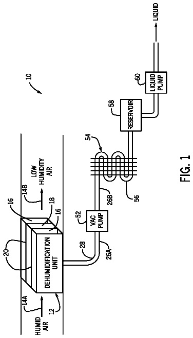
FIG. 1 is a schematic diagram of an HVAC system having a dehumidification unit in accordance with an embodiment of the present disclosure;
FIG. 2A is a perspective view of the dehumidification unit of FIG. 1 having multiple parallel air channels and water vapor channels in accordance with an embodiment of the present disclosure;
FIG. 2B is a perspective view of the dehumidification unit of FIG. 1 having a single air channel located inside a single water vapor channel in accordance with an embodiment of the present disclosure;
FIG. 3 is a plan view of an air channel and adjacent water vapor channels of the dehumidification unit of FIGS. 1, 2A, and 2B in accordance with an embodiment of the present disclosure;
FIG. 4 is a perspective view of a separation module formed using a membrane that may be used as a water vapor channel of the dehumidification unit of FIGS. 1-3 in accordance with an embodiment of the present disclosure;
FIG. 5 is a psychrometric chart of the temperature and the humidity ratio of the moist air flowing through the dehumidification unit of FIGS. 1-3 in accordance with an embodiment of the present disclosure;
FIG. 6 is a schematic diagram of the HVAC system and the dehumidification unit of FIG. 1 having a vacuum pump for removing noncondensable components from the water vapor in the water vapor extraction chamber of the dehumidification unit in accordance with an embodiment of the present disclosure;
FIG. 7 is a schematic diagram of the HVAC system and the dehumidification unit of FIG. 6 having a control system for controlling various operating conditions of the HVAC system and the dehumidification unit in accordance with an embodiment of the present disclosure;
FIG. 8 is a schematic diagram of an HVAC system having a plurality of dehumidification units arranged in series in accordance with an embodiment of the present disclosure;
FIG. 9 is a schematic diagram of an HVAC system having a plurality of dehumidification units arranged in parallel in accordance with an embodiment of the present disclosure; and
FIG. 10 is a schematic diagram of an HVAC system having a first plurality of dehumidification units arranged in series, and a second plurality of dehumidification units also arranged in series, with the first and second plurality of dehumidification units arranged in parallel in accordance with an embodiment of the present disclosure.
Detailed description of specific embodiments
Specific embodiments of the present disclosure will be described herein. In an effort to provide a concise description of these embodiments, all features of an actual implementation may not be described in the specification. It should be appreciated that in the development of any such actual implementation, as in any engineering or design project, numerous implementation-specific decisions must be made to achieve the developers' specific goals, such as compliance with system-related and business-related constraints, which may vary from one implementation to another. Moreover, it should be appreciated that such a development effort might be complex and time-consuming, but would nevertheless be a routine undertaking of design, fabrication, and manufacture for those of ordinary skill having the benefit of this disclosure.
When introducing elements of various embodiments of the present invention, the articles "a," "an," "the," and "said" are intended to mean that there are one or more of the elements. The terms "comprising," "including," and "having" are intended to be inclusive and mean that there may be additional elements other than the listed elements.
The subject matter disclosed herein relates to dehumidification systems and, more specifically, to systems and methods capable of dehumidifying air without initial condensation by establishing a humidity gradient in a dehumidification unit. In one embodiment, a water vapor permeable material (i.e., a water vapor permeable membrane) is used along at least one boundary separating an air channel from a secondary channel or chamber to facilitate the removal of water vapor from the air passing through the air channel. The secondary channel or chamber separated from the air channel by the water vapor permeable material may receive water vapor extracted from the air channel via the water vapor permeable material.
In certain embodiments, multiple dehumidification units (i.e., multiple stages) may be used in combination with each other. For example, in certain embodiments, the dehumidification units may be arranged in series with each other, such that the air flows through each of the dehumidification units, with more and more water vapor removed from the air in each successive dehumidification unit. In other embodiments, the dehumidification units may be arranged in parallel with each other such that the air is split between the dehumidification units. In addition, in even more complex systems, multiple sets of one or more dehumidification units arranged in series may be further arranged in parallel. For example, a first set of dehumidification units arranged in series with each other may be arranged in parallel with a second set of dehumidification units arranged in series with each other.
In operation, the water vapor permeable material allows the flow of H.sub.2O (which may refer to H.sub.2O as water molecules, gaseous water vapor, liquid water, adsorbed/desorbed water molecules, absorbed/desorbed water molecules, or combinations thereof) through the water vapor permeable material from the air channel to the secondary channel or chamber, while substantially blocking the flow of other components of the air flowing through the air channel from passing through the water vapor permeable material. As such, the water vapor permeable material reduces the humidity of the air flowing through the air channel by removing primarily only water vapor from the air. Correspondingly, the secondary channel or chamber is filled with primarily water vapor. It should be noted that the passage of H.sub.2O through the water vapor permeable material may be facilitated by a pressure differential. Indeed, a lower partial pressure of water vapor (i.e., a partial pressure less than the partial pressure of water vapor in the air channel) may be created in the secondary channel or chamber to further facilitate passage of the H.sub.2O through the water vapor permeable material. Accordingly, the side of the water vapor permeable material opposite the air channel may be referred to as the suction side of the water vapor permeable material.
Once the H.sub.2O has been passed through the water vapor permeable material, a vacuum pump is used to increase the partial pressure of the water vapor on the suction side of the water vapor permeable material to a minimal saturation pressure required to enable condensation of the water vapor by a condenser. That is, the vacuum pump compresses the water vapor to a pressure in a range suitable for condensing the water vapor into liquid water (e.g., a range of approximately 0.25-1.1 pounds per square inch absolute (psia), with the higher value applying to embodiments using multiple dehumidification units in series), depending on desired conditions for condensation. The condenser then condenses the water vapor into a liquid state, and the resulting liquid water is then pressurized to approximately atmospheric pressure, such that the liquid water may be rejected at ambient atmospheric conditions. By condensing the water vapor to a liquid state prior to expelling it, certain efficiencies are provided. For example, pressurizing liquid water to atmospheric pressure requires less energy than pressurizing water vapor to atmospheric pressure. It should also be noted that the dehumidification unit described herein in general uses significantly less energy than conventional systems.
While the embodiments described herein are primarily presented as enabling the removal of water vapor from air, other embodiments may enable the removal of other H.sub.2O components from air. For example, in certain embodiments, instead of a water vapor permeable material, an H.sub.2O permeable material may be used. As such, the H.sub.2O permeable material may allow the flow of one, all, or any combination of H.sub.2O components (i.e., water molecules, gaseous water vapor, liquid water, adsorbed/desorbed water molecules, absorbed/desorbed water molecules, and so forth) through the H.sub.2O permeable material from the air channel to the secondary channel or chamber, while substantially blocking the flow of other components of the air flowing through the air channel from passing through the H.sub.2O permeable material. In other words, the disclosed embodiments are not limited to the removal of water vapor from air, but rather to the removal of H.sub.2O (i.e., in any of its states) from air. However, for conciseness, the embodiments described herein are primarily focused on the removal of water vapor from air.
FIG. 1 is a schematic diagram of an HVAC system 10 having a dehumidification unit 12 in accordance with an embodiment of the present disclosure. As illustrated, the dehumidification unit 12 may receive inlet air 14A having a relatively high humidity and expel outlet air 14B having a relatively low humidity. In particular, the dehumidification unit 12 may include one or more air channels 16 through which the air 14 (i.e., the inlet air 14A and the outlet air 14B) flows. In addition, the dehumidification unit 12 may include one or more water vapor channels 18 adjacent to the one or more air channels 16. As illustrated in FIG. 1, the air 14 does not flow through the water vapor channels 18. Rather, the embodiments described herein enable the passage of water vapor from the air 14 in the air channels 16 to the water vapor channels 18, thus dehumidifying the air 14 and accumulating water vapor in the water vapor channels 18. In particular, water vapor from the air 14 in the air channels 16 may be allowed to flow through an interface 20 (i.e., a bather or membrane) between adjacent air channels 16 and water vapor channels 18, while the other components (e.g., nitrogen, oxygen, carbon dioxide, and so forth) of the air 14 are blocked from flowing through the interface 20. In general, the water vapor channels 18 are sealed to create the low pressure that pulls the water vapor from the air 14 in the air channels 16 through the interfaces 20 as H.sub.2O (i.e., as water molecules, gaseous water vapor, liquid water, adsorbed/desorbed water molecules, absorbed/desorbed water molecules, and so forth, through the interfaces 20).
As such, a humidity gradient is established between the air channels 16 and adjacent water vapor channels 18. The humidity gradient is generated by a pressure gradient between the air channels 16 and adjacent water vapor channels 18. In particular, the partial pressure of water vapor in the water vapor channels 18 is maintained at a level lower than the partial pressure of water vapor in the air channels 16, such that the water vapor in the air 14 flowing through the air channels 16 tends toward the suction side (i.e., the water vapor channels 18 having a lower partial pressure of water vapor) of the interfaces 20.
Components of air other than H.sub.2O may be substantially blocked from passing through the interfaces 20 in accordance with present embodiments. In other words, in certain embodiments, approximately 95% or more, approximately 96% or more, approximately 97% or more, approximately 98% or more, or approximately 99% or more of components of the air 14 other than H.sub.2O (e.g., nitrogen, oxygen, carbon dioxide, and so forth) may be blocked from passing through the interfaces 20. When compared to an ideal interface 20 that blocks 100% of components other than H.sub.2O, an interface 20 that blocks 99.5% of components other than H.sub.2O will experience a reduction in efficiency of approximately 2-4%. As such, the components other than H.sub.2O may be periodically purged to minimize these adverse effects on efficiency.
FIG. 2A is a perspective view of the dehumidification unit 12 of FIG. 1 having multiple parallel air channels 16 and water vapor channels 18 in accordance with an embodiment of the present disclosure. In the embodiment illustrated in FIG. 2A, the air channels 16 and the water vapor channels 18 are generally rectilinear channels, which provide a substantial amount of surface area of the interfaces 20 between adjacent air channels 16 and water vapor channels 18. Further, the generally rectilinear channels 16, 18 enable the water vapor 26A to be removed along the path of the air channels 16 before the air 14 exits the air channels 16. In other words, the relatively humid inlet air 14A (e.g., air with a dew point of 55.degree. F. or higher such that the air is appropriate for air conditioning) passes straight through the air channels 16 and exits as relatively dry outlet air 14B because moisture has been removed as the air 14 traverses along the atmospheric pressure side of the interfaces 20 (i.e., the side of the interfaces 20 in the air channels 16). In an embodiment where a single unit is dehumidifying to a 60.degree. F. saturation pressure or below, the suction side of the interfaces 20 (i.e., the side of the interfaces 20 in the water vapor channels 18) will generally be maintained at a partial pressure of water vapor that is lower than the partial pressure of water vapor on the atmospheric pressure side of the interfaces 20.
As illustrated in FIG. 2A, each of the water vapor channels 18 is connected with a water vapor channel outlet 22 through which the water vapor in the water vapor channels 18 is removed. As illustrated in FIG. 2A, in certain embodiments, the water vapor channel outlets 22 may be connected via a water vapor outlet manifold 24, wherein the water vapor 26A from all of the water vapor channels 18 is combined in a single water vapor vacuum volume 28, such as a tube or a chamber. Other configurations of the air channels 16 and the water vapor channels 18 may also be implemented. As another example, FIG. 2B is a perspective view of the dehumidification unit 12 of FIG. 1 having a single air channel 16 located inside a single water vapor channel 18 in accordance with an embodiment of the present disclosure. As illustrated, the air channel 16 may be a cylindrical air channel located within a larger concentric cylindrical water vapor channel 18. The embodiments illustrated in FIGS. 2A and 2B are merely exemplary and are not intended to be limiting.
FIG. 3 is a plan view of an air channel 16 and adjacent water vapor channels 18 of the dehumidification unit 12 of FIGS. 1, 2A, and 2B in accordance with an embodiment of the present disclosure. In FIG. 3, a depiction of the water vapor 26 is exaggerated for illustration purposes. In particular, the water vapor 26 from the air 14 is shown flowing through the interfaces 20 between the air channel 16 and the adjacent water vapor channels 18 as H.sub.2O (i.e., as water molecules, gaseous water vapor, liquid water, adsorbed/desorbed water molecules, absorbed/desorbed water molecules, and so forth, through the interfaces 20). Conversely, other components 30 (e.g., nitrogen, oxygen, carbon dioxide, and so forth) of the air 14 are illustrated as being blocked from flowing through the interfaces 20 between the air channel 16 and the adjacent water vapor channels 18.
In certain embodiments, the interfaces 20 may include membranes that are water vapor permeable and allow the flow of H.sub.2O through permeable volumes of the membranes while blocking the flow of the other components 30. Again, it should be noted that when the H.sub.2O passes through the interfaces 20, it may actually pass as one, all, or any combination of states of water (e.g., as water vapor, liquid water, adsorbed/desorbed water molecules, absorbed/desorbed water molecules, and so forth) through the interfaces 20. For example, in one embodiment, the interfaces 20 may adsorb/desorb water molecules. In another example, the interfaces 20 may adsorb/desorb water molecules and enable passage of water vapor. In other embodiments, the interfaces 20 may facilitate the passage of water in other combinations of states. The interfaces 20 extend along the flow path of the air 14. As such, the water vapor 26 is continuously removed from one side of the interface 20 as the relatively humid inlet air 14A flows through the air channel 16. Therefore, dehumidification of the air 14 flowing through the air channel 16 is accomplished by separating the water vapor 26 from the other components 30 of the air 14 incrementally as it progresses along the flow path of the air channel 16 and continuously contacts the interfaces 20 adjacent to the air channel 16 from the inlet air 14A location to the outlet air 14B location.
In certain embodiments, the water vapor channels 18 are evacuated before use of the dehumidification unit 12, such that a lower partial pressure of the water vapor 26 (i.e., a partial pressure less than the partial pressure of water vapor in the air channels 16) is created in the water vapor channels 18. For example, the partial pressure of the water vapor 26 in the water vapor channels 18 may be in the range of approximately 0.10-0.25 psia during normal operation, which corresponds to dehumidifying to a 60.degree. F. saturation pressure or below. In this example, an initial condition in the 0.01 psia range may be used to remove noncondensables, whereas the partial pressure of water vapor in the air channels 16 may be in the range of approximately 0.2-1.0 psia. However, at certain times, the pressure differential between the partial pressure of the water vapor in the water vapor channels 18 and the air channels 16 may be as low as (or lower than) 0.01 psia. The lower partial pressure of water vapor in the water vapor channels 18 further facilitates the flow of water vapor 26 from the air channels 16 to the water vapor channels 18 because the air 14 flowing through the air channels 16 is at local atmospheric pressure (i.e., approximately 14.7 psia at sea level). Since the partial pressure of water vapor in the air 14 in the air channels 16 is greater than the partial pressure of the water vapor 26 in the water vapor channels 18, a pressure gradient is created from the air channels 16 to the water vapor channels 18. As described previously, the interfaces 20 between adjacent air channels 16 and water vapor channels 18 provide a barrier, and allow substantially only water vapor 26 to flow from the air 14 in the air channels 16 into the water vapor channels 18. As such, the air 14 flowing through the air channels 16 will generally decrease in humidity from the inlet air 14A to the outlet air 14B.
The use of water vapor permeable membranes as the interfaces 20 between the air channels 16 and the water vapor channels 18 has many advantages. In particular, in some embodiments, no additional energy is required to generate the humidity gradient from the air channels 16 to the water vapor channels 18. In addition, in some embodiments, no regeneration is involved and no environmental emissions (e.g., solids, liquids, or gases) are generated. Indeed, in accordance with one embodiment, separation of the water vapor 26 from the other components 30 of the air 14 via water permeable membranes (i.e., the interfaces 20) can be accomplished at energy efficiencies much greater than compressor technology used to condense water directly from the airstream.
Because water vapor permeable membranes are highly permeable to water vapor, the costs of operating the dehumidification unit 12 may be minimized because the air 14 flowing through the air channels 16 does not have to be significantly pressurized to facilitate the passage of H.sub.2O through the interfaces 20. Water vapor permeable membranes are also highly selective to the permeation of the water vapor from the air 14. In other words, water vapor permeable membranes are very efficient at preventing components 30 of the air 14 other than water vapor from entering the water vapor channels 18. This is advantageous because the H.sub.2O passes through the interfaces 20 due to a pressure gradient (i.e., due to the lower partial pressures of water vapor in the water vapor channels 18) and any permeation or leakage of air 14 into the water vapor channels 18 will increase the power consumption of the vacuum pump used to evacuate the water vapor channels 18. In addition, water vapor permeable membranes are rugged enough to be resistant to air contamination, biological degradation, and mechanical erosion of the air channels 16 and the water vapor channels 18. Water vapor permeable membranes may also be resistant to bacteria attachment and growth in hot, humid air environments in accordance with one embodiment.
One example of a material used for the water vapor permeable membranes (i.e., the interfaces 20) is zeolite supported on thin, porous metal sheets. In particular, in certain embodiments, an ultrathin (e.g., less than approximately 2 .mu.m), dense zeolite membrane film may be deposited on an approximately 50 .mu.m thick porous metal sheet. The resulting membrane sheets may be packaged into a membrane separation module to be used in the dehumidification unit 12. FIG. 4 is a perspective view of a separation module 32 formed using a membrane that may be used as a water vapor channel 18 of the dehumidification unit 12 of FIGS. 1-3 in accordance with an embodiment of the present disclosure. Two membrane sheets 34, 36 may be folded and attached together into a generally rectangular shape with a channel for the water vapor having a width w.sub.msm of approximately 5 mm. The separation module 32 may be positioned within the dehumidification unit 12 such that the membrane coating surface is exposed to the air 14. The thinness of the metal support sheet reduces the weight and cost of the raw metal material and also minimizes resistance to the H.sub.2O diffusing through the water vapor permeable membrane film deposited on the membrane sheets 34, 36. The metallic nature of the sheets 34, 36 provides mechanical strength and flexibility for packaging such that the separation module 32 can withstand a pressure gradient of greater than approximately 60 psi (i.e., approximately 4 times atmospheric pressure).
Separation of water vapor from the other components 30 of the air 14 may create a water vapor permeation flux of approximately 1.0 kg/m.sup.2/h (e.g., in a range of approximately 0.5-2.0 kg/m.sup.2/h), and a water vapor-to-air selectivity range of approximately 5-200+. As such, the efficiency of the dehumidification unit 12 is relatively high compared to other conventional dehumidification techniques with a relatively low cost of production. As an example, approximately 7-10 m.sup.2 of membrane area of the interfaces 20 may be needed to dehumidify 1 ton of air cooling load under ambient conditions. In order to handle such an air cooling load, in certain embodiments, 17-20 separation modules 32 having a height h.sub.msm of approximately 450 mm, a length l.sub.msm of approximately 450 mm, and a width w.sub.msm of approximately 5 mm may be used. These separation modules 32 may be assembled side-by-side in the dehumidification unit 12, leaving approximately 2 mm gaps between the separation modules 32. These gaps define the air channels 16 through which the air 14 flows. The measurements described in this example are merely exemplary and not intended to be limiting.
FIG. 5 is a psychrometric chart 38 of the temperature and the humidity ratio of the moist air 14 flowing through the dehumidification unit 12 of FIGS. 1-3 in accordance with an embodiment of the present disclosure. In particular, the x-axis 40 of the psychrometric chart 38 corresponds to the temperature of the air 14 flowing through the air channels 16 of FIG. 1, the y-axis 42 of the psychrometric chart 38 corresponds to the humidity ratio of the air 14 flowing through the air channels 16, and the curve 44 represents the water vapor saturation curve of the air 14 flowing through the air channels 16. As illustrated by line 46, because water vapor is removed from the air 14 flowing through the air channels 16, the humidity ratio of the outlet air 14B (i.e., point 48) from the dehumidification unit 12 of FIGS. 1-3 is lower than the humidity ratio of the inlet air 14A (i.e., point 50) into the dehumidification unit 12 of FIGS. 1-3, while the temperature of the outlet air 14B and the inlet air 14A are substantially the same.
Returning now to FIG. 1, as described previously, a lower partial pressure of the water vapor 26 (i.e., a partial pressure less than the partial pressure of water vapor in the air channels 16) is created in the water vapor channels 18 of the dehumidification unit 12 to further facilitate the passage of H.sub.2O through the interfaces 20 from the air channels 16 to the water vapor channels 18. In certain embodiments, the water vapor channels 18 may initially be evacuated using a vacuum pump 52. In particular, the vacuum pump 52 may evacuate the water vapor channels 18 and the water vapor vacuum volume 28, as well as the water vapor outlets 22 and the water vapor manifold 24 of FIG. 2A. However, in other embodiments, a pump separate from the vacuum pump 52 may be used to evacuate the water vapor channels 18, water vapor vacuum volume 28, water vapor outlets 22, and water vapor manifold 24. As illustrated in FIG. 1, the water vapor 26 removed from the air 14 in the dehumidification unit 12 may be distinguished between the water vapor 26A in the water vapor vacuum volume 28 (i.e., the suction side of the vacuum pump 52) and the water vapor 26B expelled from an exhaust side (i.e., an outlet) of the vacuum pump 52 (i.e., the water vapor 26B delivered to a condensation unit). In general, the water vapor 26B expelled from the vacuum pump 52 will have a slightly higher pressure and a higher temperature than the water vapor 26A in the water vapor vacuum volume 28. The vacuum pump 52 may be a compressor or any other suitable pressure increasing device capable of maintaining a lower pressure on the suction side of the vacuum pump 52 than the partial pressure of water vapor in the humid air 14.
For example, the lower partial pressure of water vapor 26A maintained in the water vapor vacuum volume 28 may be in the range of approximately 0.15-0.25 psia, which corresponds to saturation temperatures of approximately 45.degree. F. to 60.degree. F., with the water vapor 26A typically be in the range of approximately 65-75.degree. F. However, in other embodiments, the water vapor 26A in the water vapor vacuum volume 28 may be maintained at a partial pressure of water vapor in the range of approximately 0.01-0.25 psia and a temperature in the range of approximately 55.degree. F. up to the highest ambient air temperature. A specific embodiment may be designed to lower the partial pressure in the water vapor vacuum volume 28 to the range of 0.01 psia to increase the capacity for removing water vapor from the air 14 to enable an evaporative cooler to process the entire air conditioning load when atmospheric conditions permit this mode of operation.
In certain embodiments, the vacuum pump 52 is a low-pressure pump configured to decrease the pressure of the water vapor 26A in the water vapor vacuum volume 28 to a lower partial pressure than the partial pressure of water vapor on the atmospheric side of the interfaces 20 (i.e., the partial pressure of the air 14 in the air channels 16). On the exhaust side of the vacuum pump 52, the partial pressure of the water vapor 26B has been increased just high enough to facilitate condensation of the water vapor (i.e., in a condensation unit 54). Indeed, the vacuum pump 52 is configured to increase the pressure such that the water vapor 26B in the condensation unit 54 is at a pressure proximate to a minimal saturation pressure in the condensation unit 54.
As an example, when in operation, the air 14 may enter the system at a partial pressure of water vapor of 0.32 psia, which corresponds to a humidity ratio of 0.014 pounds of H.sub.2O per pounds of dry air. The system may be set to remove 0.005 pounds of H.sub.2O per pounds of dry air from the air 14. Pressure differentials across the interfaces 20 may be used to create a flow of H.sub.2O through the interfaces 20. For example, the partial pressure of water vapor in the water vapor vacuum volume 28 may be set to approximately 0.1 psia. The pressure of the water vapor 26B is increased by the vacuum pump 52 in a primarily adiabatic process, and as the pressure of the water vapor 26B increases, the temperature increases as well (in contrast to the relatively negligible temperature differential across the interfaces 20). As such, if for example the pressure of the water vapor 26B is increased in the vacuum pump 52 by 0.3 psi (i.e., to approximately 0.4 psia), the condensation unit 54 is then capable of condensing the water vapor 26B at a temperature of approximately 72-73.degree. F., and the temperature of the water vapor 26B will increase to a temperature substantially higher than the condenser temperature. The system may continually monitor the pressure and temperature conditions of both the upstream water vapor 26A and the downstream water vapor 26B to ensure that the water vapor 26B expelled from the vacuum pump 52 has a partial pressure of water vapor just high enough to facilitate condensation in the condensation unit 54. It should be noted that the pressure and temperature values presented in this scenario are merely exemplary and are not intended to be limiting.
Note that as the pressure difference from the water vapor 26A entering the vacuum pump 52 to the water vapor 26B exiting the vacuum pump 52 increases, the efficiency of the dehumidification unit 12 decreases. For example, in a preferred embodiment, the vacuum pump 52 will be set to adjust the pressure of the water vapor 26B in the condensation unit 54 slightly above the saturation pressure at the lowest ambient temperature of the cooling media (i.e., air or water) used by the condensation unit 54 to condense the water vapor 26B. In another embodiment, the temperature of the water vapor 26B may be used to control the pressure in the condensation unit 54. The temperature of the water vapor 26B expelled from the vacuum pump 52 may be substantially warmer than the humid air 14A (e.g., this temperature could reach 200.degree. F. or above depending on a variety of factors). Because the vacuum pump 52 only increases the pressure of the water vapor 26B to a point where condensation of the water vapor 26B is facilitated (i.e., approximately the saturation pressure), the power requirements of the vacuum pump 52 are relatively small, thereby obtaining a high efficiency from the dehumidification unit 12.
Once the water vapor 26B has been slightly pressurized (i.e., compressed) by the vacuum pump 52, the water vapor 26B is directed into the condensation unit 54, wherein the water vapor 26B is condensed into a liquid state. In certain embodiments, the condensation unit 54 may include a condensation coil 56, a pipe/tube condenser, a flat plate condenser, or any other suitable system for causing a temperature below the condensation point of the water vapor 26B. The condensation unit 54 may either be air cooled or water cooled. For example, in certain embodiments, the condensation unit 54 may be cooled by ambient air or water from a cooling tower. As such, the costs of operating the condensation unit 54 may be relatively low, inasmuch as both ambient air and cooling tower water are in relatively limitless supply.
Once the water vapor 26B has been condensed into a liquid state, in certain embodiments, the liquid water from the condensation unit 54 may be directed into a reservoir 58 for temporary storage of saturated vapor and liquid water. However, in other embodiments, no reservoir 58 may be used. In either case, the liquid water from the condensation unit 54 may be directed into a liquid pump 60 (i.e., a water transport device), within which the pressure of the liquid water from the condensation unit 54 is increased to approximately atmospheric pressure (i.e., approximately 14.7 psia) so that the liquid water may be rejected at ambient conditions. As such, the liquid pump 60 may be sized just large enough to increase the pressure of the liquid water from the condensation unit 54 to approximately atmospheric pressure. Therefore, the costs of operating the liquid pump 60 may be relatively low. In addition, the liquid water from the liquid pump 60 may be at a slightly elevated temperature due to the increase in the pressure of the liquid water. As such, in certain embodiments, the heated liquid water may be transported for use as domestic hot water, further increasing the efficiency of the system by recapturing the heat transferred into the liquid water.
The description continues in the full USPTO document.
 Lapsed, fee not paid11 drawings