 Lapsed, fee not paid3 drawings
Industrial Equipment · US 8,684,880 B2
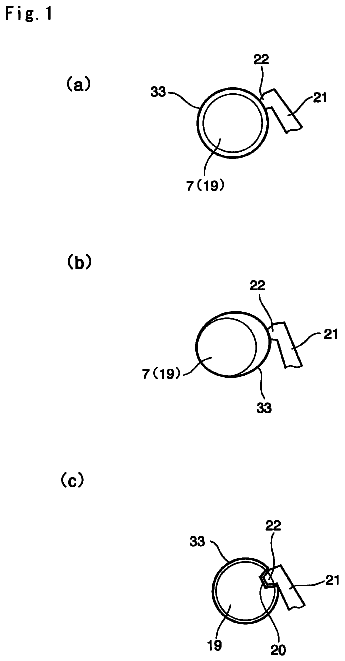
Rattling noise reduction device for vehicle
A simply structured rattling noise reduction device for a vehicle capable of preventing rattling certainly under neutral position.
US 8,685,089 B2 · Assignee: The Regents of the University of Colorado · Inventors: Kahook; Malik Y. et al.
Sheet 1 of 13 from the published document. All sheets in the USPTO PDF
A shape memory polymer (SMP) intraocular lens may have a refractive index above 1.45, a Tg between 10.degree. C. and 60.degree. C., inclusive, de minimis or an absence of glistening, and substantially 100% transmissivity of light in the visible spectrum. The intraocular lens is then rolled at a temperature above Tg of the SMP material. The intraocular device is radially compressed within a die to a diameter of less than or equal to 1.8 mm while maintaining the temperature above Tg. The compressed intraocular lens device may be inserted through an incision less than 2 mm wide in a cornea or sclera or other anatomical structure. The lens can be inserted into the capsular bag, the ciliary sulcus, or other cavity through the incision. The SMP can substantially achieve refractive index values of greater than or equal to 1.45.
The human eye functions to provide vision by transmitting light through a clear outer portion called the cornea, and focusing the image by way of a crystalline lens onto a retina. The quality of the focused image depends on many factors including the size and shape of the eye, and the transparency of the cornea and the lens. When age or disease causes the lens to become less transparent, vision deteriorates because of the diminished light which can be transmitted to the retina. This deficiency in the lens of the eye is medically known as a cataract. An accepted treatment for this condition is surgical removal of the lens and replacement of the lens function by an artificial intraocular lens (IOL). Intraocular lenses are employed as replacements for the crystalline lens after either extracapsular or intracapsular surgery for the removal of a cataract. In the United States, the majority of
1 of 13 drawing sheets so far from the published document, cropped to the drawing. Every sheet is in the USPTO PDF.
What the patent claimed, word for word. All of it is now free to use.
The technology described herein relates to artificial intraocular lenses.
The human eye functions to provide vision by transmitting light through a clear outer portion called the cornea, and focusing the image by way of a crystalline lens onto a retina. The quality of the focused image depends on many factors including the size and shape of the eye, and the transparency of the cornea and the lens.
When age or disease causes the lens to become less transparent, vision deteriorates because of the diminished light which can be transmitted to the retina. This deficiency in the lens of the eye is medically known as a cataract. An accepted treatment for this condition is surgical removal of the lens and replacement of the lens function by an artificial intraocular lens (IOL).
Intraocular lenses are employed as replacements for the crystalline lens after either extracapsular or intracapsular surgery for the removal of a cataract. In the United States, the majority of cataractous lenses are removed by a surgical technique called phacoemulsification. During this procedure, an opening is made in the anterior capsule and a thin phacoemulsification cutting tip is inserted into the diseased lens and vibrated ultrasonically. The vibrating cutting tip liquefies or emulsifies the lens so that the lens may be aspirated out of the eye. The diseased lens, once removed, is replaced by an artificial lens.
Intraocular lenses are generally of two types, those that are placed in the anterior chamber, i.e., between the iris and the cornea, and those that are placed in the posterior chamber, i.e., behind the iris. Both types of lenses are conventionally employed with the choice between an anterior chamber and a posterior chamber lens being partly dictated by requirements of the patient and partly dictated by the preferences of the physician inserting the lens. A third type of lens, known as iris-fixated lenses because they are secured to the iris periphery, can be thought of as being within one of the two types above, in that their optic portion is in either the anterior or posterior chamber.
Intraocular lenses normally consist of an optic with at least one and preferably two or more haptics that extend generally radially from the optic and contain distal portions that normally seat in the scleral spur for an anterior chamber lens and either in the ciliary sulcus or within the lens capsule for a posterior chamber lens. The optic normally comprises a circular transparent optical lens. The haptic in most lenses is a flexible fiber or filament having a proximate end affixed to the lens and having a distal end extending radially away from the periphery of the lens to form a seating foot. Several haptic designs are currently in use, for example, a pair of C-shaped loops in which both ends of each loop are connected to the lens, and, for example, J-shaped loops in which only one end of the loop is affixed to the lens.
Haptics are usually radially resilient and extend outwardly from the periphery of the lens and gently, but elastically, engage appropriate circumferential eye structures adjacent the iris or within the capsular bag. This resiliency is due to the conventional elastic properties of the materials of the haptic. The result is a haptic which when compressed and released will uncontrollably spring back immediately. This property makes the process of implantation and final positioning of the lens difficult since the haptics must be constrained during implantation. Also, once situated, the flexibility of the conventional haptic material makes the lens susceptible to decentration from being pushed by vitreous pressure from behind the lens or shifting due to pressure from adjacent ocular tissue. Also, the forces generated by the elastic recoil of the haptic release may damage the delicate local tissue.
The optimum position for a posterior chamber lens is in the capsular bag. This is an extremely difficult maneuver for the surgeon to accomplish. When a posterior chamber lens is employed it must be placed through the small pupillary opening, and the final haptic position is hidden behind the iris and not visible to the surgeon. It is therefore highly desirable to keep the overall dimensions of the posterior chamber lens as small as possible during implantation, letting it expand when it is finally situated where the surgeon intends, usually in the capsular bag. A small device is easier to manipulate in the eye, reduces the chance of the haptics coming in contact with the corneal endothelial tissue, and allows the surgeon ease of insertion, as he must often insert a lens with a 14 mm overall dimension through a pupil of 5 to 8 mm diameter. A smaller lens also reduces the lens/iris contact and can better guarantee that the intraocular lens and its haptics will be in the capsular bag.
In recent years intraocular lenses with and without haptics having relatively soft body portions have been provided such that the body portion could be folded generally across the diameter thereof for insertion into a smaller opening during implantation of the lens. Lenses formed of liquid or hydrogel constrained within a sheath have been designed which allow the lens body to be folded before insertion and then subsequently filled when in position. Unfortunately, the soft materials used for the bodies of these lenses lack the restorative strength sometimes required to return to their original shape.
Further, these lens types are typically deployed using either an elastic release mechanism, wherein mechanical energy stored by bending the elastic material is released when the mechanical constraint is removed, or through water uptake, also known as hydration, wherein the lens gradually absorbs water through an osmotic diffusion process. Both processes are difficult to control. In the former case, the elastic recoil may damage local tissue or may move the lens away from the center. In the latter case, the ultimate shape of the lens may become distorted if the expanding lens comes into contact with surrounding tissue. Further, hydrating materials are known to possess poor shape recovery properties.
In the natural lens, bifocality of distance and near vision is provided by a mechanism known as accommodation. The natural lens, early in life, is soft and contained within the capsular bag. The bag is suspended from the ciliary muscle by the zonules. Relaxation of the ciliary muscle tightens the zonules, and stretches the capsular bag. As a result, the natural lens tends to flatten. Tightening of the ciliary muscle relaxes the tension on the zonules, allowing the capsular bag and the natural lens to assume a more rounded shape. In this way, the natural lens can be focused alternatively on near and far objects. As the lens ages, it also becomes harder and is less able to change shape in reaction to the tightening of the ciliary muscle. This makes it harder for the lens to focus on near objects--a medical condition known as presbyopia. Presbyopia affects nearly all adults over the age of 45 or 50.
Typically, when a cataract or other disease requires the removal of the natural lens and replacement with an artificial IOL, the IOL is a monofocal lens, requiring that the patient use a pair of spectacles or contact lenses for near vision. Some bifocal IOLs have been created, but are not been widely accepted. Some IOL designs are single optic lenses having flexible haptics that allow the optic to move forward and backward in reaction to movement of the ciliary muscle. However, the amount of movement of the optic in these single-lens systems may be insufficient to allow for a useful range of accommodation. In addition, the eye must be medicated for one to two weeks to decrease eye movement in order for capsular fibrosis to entrap the lens that thereby provide for a rigid association between the lens and the capsular bag. Further, the commercial models of these lenses are made from a hydrogel or silicone material. Such materials are not resistive to the formation of posterior capsule opacification ("PCO"). The treatment for PCO is a capsulotomy using a Nd:YAG laser that vaporizes a portion of the posterior capsule. Such destruction of the posterior capsule may destroy the mechanism of accommodation of these lenses.
Known accommodative lenses also lack extended depth of focus in addition to having poor accommodation performance. Such known lenses further require precise lens sizing for proper function over a range of capsular bag sizes and lack long-term capsular fixation and stability. Further, as current lens replacement surgeries move towards smaller incision size, IOLs in general require the ability to be delivered through such small incisions.
Dual-optic lenses leverage the ability of the ciliary body-zonule complex to change the shape of the capsular bag. This allows the inter-lens distance to change, thereby allowing a change in refractive error. These dual-optic lenses can be large secondary to the optical hardware needed to create this optical system and requires larger corneal incisions to insert into the eye.
Intracorneal lenses are designed to treat refractive error or presbyopia. Intracorneal lenses include corneal implants and lenses, which are inserted through a small incision in the cornea created by a blade or a laser. The pocket formed by the incision in the cornea is used to position the implant to change the shape of the cornea. In the case of a lens implant, the pocket is used to position the refractive lens in the optically effective location. Some lenses create a pinhole-type effect to treat presbyopia. As current intraocorneal lenses move towards smaller incision size, devices in general require the ability to be delivered through such small incisions. Laser technology such as the femtosecond laser has enhanced the ability to create these smaller corneal wounds and pockets for implantation.
Phakic intraocular lenses are implanted either in the anterior chamber supported by the angle structures or in the posterior sulcus immediately posterior to the iris and anterior to the native lens. The lens is implanted through a minimally invasive wound at the limbus and inserted into or through the anterior chamber. The lenses are used to treat refractive error and have the risk of causing trauma to the lens and/or angle structures. Smaller incisions require folding the lens and then lens deployment in the eye, which increases the risk of damage to intraocular structures.
The information included in this Background section of the specification, including any references cited herein and any description or discussion thereof, is included for technical reference purposes only and is not to be regarded subject matter by which the scope of the invention as defined in the claims is to be bound.
Shape-memory polymers (SMP) are a class of smart materials that can be tailored to have significant mechanical property changes in response to a given stimulus. The ability to recover from large deformations and adapt to differing environmental conditions greatly facilitates use of SMP devices in minimally invasive surgery. Current shape memory polymer formulations can be created to have independently programmed modulus and glass transition temperatures (Tg). The ability to precisely control mechanical properties of SMP along with the transparent nature of the material, a refractive index in ranges very similar to the range of a human lens (1.386-1.406 and greater), and proven biocompatibility allows for the creation of unique solutions for treatment of various ophthalmic diseases. Therefore, there are many aspects of a hydrophobic, acrylate-based, SMP intraocular lens which are appealing in view of other lens options.
One clear advantage of the SMP systems disclosed herein is the dramatic capability to vary mechanical properties by changing material properties such as cross-linked weight percentage, fractions of each component co-monomer, and other ingredient properties. This provides the capability to design the required mechanical properties for the specific application into the material. For example, varying Tg for particular SMP formulations affects resultant rubbery modulus. Additional property changes can be incorporated, for example, by varying the weight percentage of the co-monomers forming the SMP. The SMP material qualities may also be leveraged to change the radius of curvature of the anterior and posterior surfaces of particular IOL designs with heat, UV light, or other processes to change the central and/or paracentral power of the particular lens.
A variety of intraocular lenses may be formed of a shape memory polymer with high degrees of "shape certainty" or "shape-fixity" (i.e., the accuracy of the recovered shape after transition from the deformed shape back to the permanent shape). The lenses are deformed and compressed into a compact preoperative shape that allows for implantation through a small incision, gently unfurl and expand into guaranteed post-operative shapes (permanent shapes), and provide an integrated haptic for a stable and nontraumatic apposition to ciliary sulcus, capsular bag, or anterior chamber angle structures. The SMP lenses may be deformed and compressed to sizes smaller than currently known and available for implantation through an incision size under 2 mm, which is currently the lower limit.
In one exemplary implementation, a method of manufacturing an intraocular device includes providing a shape memory polymer (SMP) material with a Tg, forming the SMP material in a permanent intraocular device form, mechanically compressing the intraocular device at a temperature above Tg to deform the intraocular device into a smaller volume; and cooling the deformed intraocular device while still in compression to a temperature below Tg to thereby create a stable deformed intraocular device with a delivery profile allowing for insertion through an incision of 2 mm or less. In one embodiment, the intraocular device may be rolled at a temperature above Tg of the SMP material. The rolled intraocular device may then be cooled while still in a rolled form to a temperature below Tg to thereby create a stable rolled intraocular device. The intraocular device may then be mechanically compressed to a diameter of less than 1.8 mm. In another embodiment, the intraocular device may be rolled at a temperature above Tg of the SMP material. The intraocular device may then be radially compressed within a die to a diameter of less than 1.8 mm while maintaining the temperature above Tg.
In another exemplary implementation, a shape memory polymer (SMP) intraocular lens may have a refractive index above 1.45, a Tg between 15.degree. C. and 40.degree. C., inclusive, de minimis or an absence of glistening, and substantially 100% transmissivity of light in the visible spectrum. In one embodiment, the SMP intraocular lens may be formed of a combination of 50 weight percent tBA, 28 weight percent isobutyl acrylate, and 22 weight percent PEGDMA 1000. In another embodiment, the SMP intraocular lens may be formed of a combination of 22 weight percent tBA and 78 weight percent PEGDMA 1000. In a further embodiment, the SMP intraocular lens may be formed of a combination of 65 weight percent tBA, 13 weight percent butyl acrylate, and 22 weight percent PEGDMA 1000.
In a further exemplary implementation, a method of implanting an intraocular lens device includes making an incision in a cornea or sclera less than 2 mm wide. In one embodiment, an intraocular lens is into the capsular bag through the incision. In another embodiment, an intraocular lens is inserted into the ciliary sulcus through the incision. In another embodiment, a method of implanting an intraocular lens device includes making an incision into a cornea less than 2 mm wide to access the anterior chamber. An intraocular lens is then inserted into the anterior chamber through the incision. In a further embodiment, a method of implanting an intracorneal implant device includes making an incision into a cornea less than 2 mm wide to create a tunnel in the cornea. An intracorneal implant device is then inserted into the anterior chamber through the incision.
This Summary is provided to introduce a selection of concepts in a simplified form that are further described below in the Detailed Description. This Summary is not intended to identify key features or essential features of the claimed subject matter, nor is it intended to be used to limit the scope of the claimed subject matter. A more extensive presentation of features, details, utilities, and advantages of the present invention as defined in the claims is provided in the following written description of various embodiments of the invention and illustrated in the accompanying drawings.
FIG. 1 is a graph depicting the storage modulus vs. temperature attributes for several exemplary SMP formulations.
FIG. 2 is a graph depicting the UV blocking properties and optical clarity of the exemplary SMP formulations of FIG. 9 as a percentage of transmission over a range of wavelengths in the UV and visible spectrum.
FIG. 3 is a graph depicting the storage modulus vs. temperature attributes for several exemplary SMP formulations.
FIG. 4 is a graph depicting the UV blocking properties and optical clarity of the exemplary SMP formulations of FIG. 11 as a percentage of transmission over a range of wavelengths in the UV and visible spectrum.
FIG. 5 is a graph depicting the compression properties of the exemplary SMP formulations of FIG. 11.
FIG. 6 is a graph depicting the tensile properties of an exemplary SMP formulation at two different rates of strain.
FIG. 7 is an optical profilometry image of a sample SMP IOL lens surface showing average surface roughness.
FIG. 8A is an isometric view of an exemplary shape memory polymer (SMP) intraocular lens (IOL) with placement haptics in a permanent or deployed configuration.
FIG. 8B is a top plan view of the SMP IOL of FIG. 1A.
FIG. 8C is a front elevation view of the SMP IOL of FIG. 1A
FIG. 8D is a side elevation view of the SMP IOL of FIG. 1A.
FIG. 9A is a top plan view of an exemplary SMP IOL placed on a rolling die with a channel for rolling the SMP IOL.
FIG. 9B is a front elevation view of the rolling die of FIG. 2A with the SMP IOL folded into the channel under compression by a wire running axially down the channel.
FIG. 10A is a schematic front elevation view of the rolling die of FIG. 2A with the edges of the SMP IOL folded over and the rolling die cooled below Tg.
FIG. 10B is a schematic elevation view of the SMP IOL removed from the rolling die and maintaining a deformed, rolled configuration.
FIG. 11 is a schematic diagram of the rolled SMP IOL placed in a fabric sock.
FIG. 12A is a top plan view, in cross section of the SMP IOL within the fabric sock being pulled through a tube of decreasing diameter formed in a compression die heated above Tg.
FIG. 12B is a is a top plan view, in cross section of the SMP IOL within the fabric sock compressed within the smallest diameter section of the tube while the compression die is cooled below Tg.
FIG. 13 is a schematic elevation view of the SMP IOL removed from the compression die and sock maintaining a deformed, rolled, extended, and radially compressed configuration.
FIG. 14A is a schematic top plan view of a folding and compression tool used to fold a SMP IOL in conjunction with a temperature-regulated compression system.
FIG. 14B is a schematic side elevation view in cross section of the tool of FIG. 7A used in conjunction with a temperature-regulated compression tool.
FIG. 14C is a schematic side elevation view in cross section of the folding and compression tool in a compressed position with the temperature-regulated compression tool.
Known acrylic lens materials are unable to be compressed significantly to achieve desired functionality. While various methodologies are known to fold or roll acrylic IOLs, these merely address the need to reduce the form factor of a deployed shape for the purposes of minimizing the required incision size for implantation. The actual volume displaced by these lenses remains constant so there is a limit on the minimum size that such IOLs can reach. Further, the ability to fold or roll these IOLs is limited by the ability of the material to resist strain caused by the stress of folding and return to a desired shape and provide the necessary optical qualities after implantation. Further, there is little control over the speed and force with which deployment of a lens occurs once it is implanted, which often causes trauma to tissues which engage haptics of the IOL.
In contrast, the SMP IOLs disclosed herein are actually more deformable (in some cases greater than 65% compression and greater than 250% tensile strain) and thus the volume displaced by such devices can actually be reduced for implantation. This allows for implantation through reduced incision sizes (sub 2 mm and even sub 1.8 mm) and thus reduced trauma to the human eye. Several other benefits are also achievable by using SMP IOLs. It is notable that the refractive index of many of the formulations (n.sub.0.apprxeq.1.464) is relatively high (higher than the refractive index of human lens tissue) and thus allows for the possibility of reducing the thickness of the lens and therefore of the size of the delivery profile. The refractive index of SMP IOLs can further be modified by formulation of the SMP material. The formulations of the SMP materials can also be adjusted to slow or time delay the shape recovery process in order to reduce trauma to tissue in the implant location and to allow the surgeon adequate time for manipulation and placement of the IOL in the proper location. With some SMP formulations, post implant modification is possible, e.g., to change the curvature of the optic or the index of refraction. This may be realized through application of non-intrusive heating of the SMP IOL, or portions thereof, post-implant via laser or ultrasound. Such heating may be applied to particular sections of the SMP IOL which have different cross-link weight percentages of material (and thus different Tg in those areas) to allow activation of a secondary or tertiary shape change, which may be used to effect changes to the refractive index, the curvature of the optic, or the expansion of the haptics. For example, the configuration of the haptic-optic junction may be changed to modify the vault of the optic by heating the junction. Such secondary or tertiary shape changes may also be used to promote interaction with the lens capsule, vitreous, zonules and surrounding tissues to help in accommodation. In addition, the baseline positioning of the two optics in a dual optic accommodative intraocular lens system can be changed even after implantation.
Further, some SMP IOL formulations may be impregnated with various drugs that may be eluted from the SMP IOL once implanted in vivo to assist with the healing process of the optical tissue traumatized during implantation or to deliver therapeutic medications to treat other ocular diseases. The medication or active ingredient (e.g., a biologic agent) may be integrated into the SMP IOL as part of the polymerization process, within a swelling agent (e.g., as a chemical or physical hydrogel polymer structure), or as a biodegradeable, drug-eluting polymer portion of the final SMP IOL device. Exemplary drugs that may be impregnated in the SMP IOL may include antibiotics, anti-inflammatories, anti-histamines, anti-allergy, biologic agents (e.g., anti-VEGF agents, siRNAs, etc), and glaucoma medications (i.e., medications to decrease eye pressure, which include, but are not limited to, prostaglandins, parasympathetic/sympathetic-based medications, alpha agonists, beta blockers, carbonic anhydrase inhibitors, Rho Kinase inhibitors, adenosine agonists, endothelin agonists and antagonists, etc). Other agents that may be linked to an SMP IOL include viral vectors and cell-based therapeutics.
Shape Memory Polymer Materials
SMP materials have significant capacity to change shape or otherwise activate with a mechanical force in response to an external stimulus. The stimulus may be light, heat, chemical, or other types of energy or stimuli. The thermomechanical response of SMP materials may be controlled through formulation to predict and optimize shape-memory properties. Shape memory polymer devices may be designed and optimized to a high degree of tailorability that are capable of adapting and responding to particular biomedical applications and patient physiology.
A polymer may be considered a SMP if the original shape of the polymer can be deformed and remain stable in the deformed state until acted upon by an external stimulus, and then the original shape can be recovered by exposing the material to the appropriate stimulus. In one implementation, the stimulus may be heat. The original shape may be set by molding, extruding, stamping, or other typical polymer processing process. In addition, a disc, rod, or other configuration of the material may be formed by the above processes and then shaped into a final shape with cryolathing, which is a process involving freezing of the material followed by laser and/or mechanical cutting of the material into a final shape. The temporary shape may be set by thermo-mechanical deformation. Heating the deformed SMP material above a shape deformation recovery temperature results in recovery of the original shape, even if the original molded shape of the polymer is altered mechanically at a lower temperature than the deformation recovery temperature. SMP materials disclosed for use in the applications herein have the ability to recover large deformation upon heating and in appropriate formulations with greater than 99% accuracy of the original shape.
In one implementation using heat stimulus, a polymer transition temperature may be tailored to provide for a deformation recovery temperature, at body temperature, about 37.degree. C.; i.e., the glass transition temperature, Tg, of the polymer is designed to be about 37.degree. C. The distinct advantage of this approach is the utilization of the thermal energy of the human body to naturally activate the SMP material. For some applications, the mechanical properties (e.g., stiffness) of the material are strongly dependent on Tg. Thus, it may be difficult to design an extremely stiff device when Tg is close to the body temperature due to the compliant nature of the polymer. Another consideration in medical applications is that the required storage temperature of a shape memory polymer with Tg about 37.degree. C. will typically be below room temperature requiring "cold" storage before deployment. In higher temperature transportation or storage environments, the folded shape may be retained through the use of a constraining device which does not allow the device to deploy into its initially molded shape.
In an alternative implementation, the recovery temperature is higher than the body temperature, i.e., Tg>37.degree. C. The advantage of this implementation is that the storage temperature can be equal to room temperature facilitating easy storage of the device and avoiding unwanted deployments before use. the folded shape may be retained through the use of a constraining device which does not allow the device to deploy into its initially molded shape. However, local heating of the material upon deployment may be needed to induce recovery of the SMP material. Local damage to some tissues in the human body may occur at temperatures approximately 5 degrees above the body temperature through a variety of mechanisms including apoptosis and protein denaturing. Local heating bursts may be used to minimize exposure to elevated temperatures and circumvent tissue damage. The use of one method over the other is a design decision that depends on the targeted body system and other device design constraints such as required in-vivo mechanical properties.
A SMP material or network may include dissolving materials which may include part of the network or may be included in the formulation of the network before the network is polymerized (e.g., as an aggregate, mixed into the formulation). Dissolving materials may include materials that disperse over time, even if the material or part of the material does not actually dissolve or enter into a solution with a solvent. In other words, a dissolving material as used herein may be any material that may be broken down by an anticipated external environment of the polymer. In one embodiment, a dissolving material is a drug which elutes out of a SMP network. A dissolving material may be attached by chemical or physical bonds to the polymer network and may become disassociated with the polymer network over time.
Dissolving materials, through their dissolution over time, may be used for many purposes. For example, the dissolution of a material may affect a dissolution or break-up of a biomedical device over time. Alternatively, the dissolution of a material may elute a drug, achieving a pharmacological purpose. Medications or drugs can be infused into SMP devices to aid in healing (e.g., anti-inflammatory), avoid complications (e.g., anti-thrombotic), or to combat potential infection (e.g., antibiotic). Medications may be added by injection into the liquid polymer before curing. Medications may also be added to SMP devices post-polymerization using various surface modification or coating techniques, for example, plasma deposition.
In certain embodiments, the SMP polymer segments can be natural or synthetic, although synthetic polymers are preferred. The polymer segments may be non-biodegradable. Non-biodegradable polymers used for medical applications preferably do not include aromatic groups, other than those present in naturally occurring amino acids. The SMP utilized in the IOLs disclosed herein may be nonbiodegradable. In some implementations, it may be desirable to use biodegradable polymers in the SMP IOLs, for example, when temporary sterilization is desired or additional functionality is necessary.
The polymers are selected based on the desired glass transition temperature(s) (if at least one segment is amorphous) or the melting point(s) (if at least one segment is crystalline), which in turn is based on the desired application, taking into consideration the environment of use. Representative natural polymer blocks or polymers include proteins such as zein, modified zein, casein, gelatin, gluten, serum albumin, and collagen, and polysaccharides such as alginate, celluloses, dextrans, pullulane, and polyhyaluronic acid, as well as chitin, poly(3-hydroxyalkanoate), especially poly(.beta.-hydroxybutyrate), poly(3-hydroxyoctanoate), and poly(3-hydroxy fatty acids). Representative natural biodegradable polymer blocks or polymers include polysaccharides such as alginate, dextran, cellulose, collagen, and chemical derivatives thereof (substitutions, additions of chemical groups, for example, alkyl, alkylene, hydroxylations, oxidations, and other modifications routinely made by those skilled in the art), and proteins such as albumin, zein, and copolymers and blends thereof, alone or in combination with synthetic polymers.
Representative synthetic polymer blocks or polymers include polyphosphazenes, poly(vinyl alcohols), polyamides, polyester amides, poly(amino acid)s, synthetic poly(amino acids), polyanhydrides, polycarbonates, polyacrylates, polyalkylenes, polyacrylamides, polyalkylene glycols, polyalkylene oxides, polyalkylene terephthalates, polyortho esters, polyvinyl ethers, polyvinyl esters, polyvinyl halides, polyvinyl pyrrolidone, polyesters, polylactides, polyglycolides, polysiloxanes, polyurethanes and copolymers thereof. Examples of suitable polyacrylates include poly(methyl methacrylate), poly(ethyl methacrylate), poly(butyl methacrylate), poly(isobutyl methacrylate), poly(ethylene glycol dimethacrylate) (PEGDMA), diethylene glycol dimethacrylate (DEGDMA), poly(ethylene glycol) diacrylate (PEGDA), poly(hexyl methacrylate), poly(isodecyl methacrylate), poly(lauryl methacrylate), poly(phenyl methacrylate), poly(ethyl acrylate), poly(methyl acrylate), poly(isopropyl acrylate), butyl acrylate, poly(butyl acrylate), poly (tert-butyl acrylate), poly(isobutyl acrylate), poly(isobornyl acrylate) and poly(octadecyl acrylate).
Synthetically modified natural polymers include cellulose derivatives such as alkyl celluloses, hydroxyalkyl celluloses, cellulose ethers, cellulose esters, nitrocelluloses, and chitosan. Examples of suitable cellulose derivatives include methyl cellulose, ethyl cellulose, hydroxypropyl cellulose, hydroxypropyl methyl cellulose, hydroxybutyl methyl cellulose, cellulose acetate, cellulose propionate, cellulose acetate butyrate, cellulose acetate phthalate, carboxymethyl cellulose, cellulose triacetate, and cellulose sulfate sodium salt. These are collectively referred to herein as "celluloses."
Representative synthetic degradable polymer segments include polyhydroxy acids, such as polylactides, polyglycolides and copolymers thereof poly(ethylene terephthalate); polyanhydrides, poly(hydroxybutyric acid); poly(hydroxyvaleric acid); poly[lactide-co-(.epsilon.-caprolactone)]; poly[glycolide-co-(.epsilon.-caprolactone)]; polycarbonates, poly(pseudo amino acids); poly(amino acids); poly(hydroxyalkanoate)s; polyanhydrides; polyortho esters; and blends and copolymers thereof. Polymers containing labile bonds, such as polyanhydrides and polyesters, are well known for their hydrolytic reactivity. The hydrolytic degradation rates of these polymer segments can generally be altered by simple changes in the polymer backbone and their sequence structure.
Examples of non-biodegradable synthetic polymer segments include ethylene vinyl acetate, poly(meth)acrylic acid, polyamides, polyethylene, polypropylene, polystyrene, polyvinyl chloride, polyvinylphenol, and copolymers and mixtures thereof. The polymers can be obtained from commercial sources such as Sigma Chemical Co., St. Louis, Mo.; Polysciences, Warrenton, Pa.; Aldrich Chemical Co., Milwaukee, Wis.; Fluka, Ronkonkoma, N.Y.; and BioRad, Richmond, Calif. Alternately, the polymers can be synthesized from monomers obtained from commercial sources, using standard techniques.
In some implementations, thiol-vinyl and thiol-yne polymer compounds as disclosed in international application no. PCT/US2009/041359 entitled "Thiol-vinyl and thiol-yne systems for shape memory polymers" filed 22 Apr. 2009, which is hereby incorporated by reference herein in its entirety, may be used to form IOLs. In other implementations, polymer formulations may undergo a two-stage curing process in which a second, photo-induced polymerization of still unreacted functional groups is undertaken after an initial cure stage. Such a dual cure system for manufacturing SMP materials is described in U.S. provisional patent application No. 61/410,192 entitled "Dual-cure polymer systems" filed 10 Nov. 2010, which is hereby incorporated by reference herein in its entirety.
Tailoring of specific SMP formulations allows IOLs to be created to meet specific design requirements and to be manufactured using scalable liquid injection manufacturing techniques. SMP formulations were developed to optimize the following properties: Shape fixity of >98.5%; Recovery rates of between 0.25 seconds to 600 seconds, including clinically desirable rates of between 3 and 25 seconds, inclusive; Minimum device deformations of at least 40% in any dimension during the manufacturing process, and preferentially of 100-200%; Rubbery modulus of 250 kPa to 20,000 kPa; Tailoring of Tg for folding, compression, and injection; Glistening-free (an industry term describing optical imperfections possible in polymer formulations for intraocular lenses); UV blocking capabilities; Coloration of blue, yellow, red, and green, or combinations thereof; Cycle times for liquid injection manufacturing of 30 seconds to 20 minutes; Ability to tolerate high temperature mold-based manufacturing, e.g., temperatures of as much as 400 degrees; Capability to tolerate high-pressure mold-based manufacturing, specifically pressures of as much as 50 Mpa; Ability to flow through extremely narrow channels (<100 microns diameter) during the mold-based manufacturing process (i.e., low viscosity at manufacturing temperatures); and Volume shrinkage to permanent shape of 3%-15% or less after thermal curing in the mold-based manufacturing process. Some exemplary SMP formulations and their measured properties are reported in Table A below. In one formulation, tert-butyl acrylate (tBA) is combined with poly(ethylene glycol) dimethacrylate (PEGDMA) 1000 as a cross-linker. The weight percentages of each may be varied to design an SMP with particular desired material properties.
TABLE-US-00001 TABLE A Max Com- Rubbery Tensile pressive Tg Modulus Strain Strain Glistening Formulation (.degree. C.) (MPa) RI (%) (%) Properties tBA (78%): 40 2.5 1.465 >250 >65 Glistening PEGDMA Free 1000 (22%) tBA (65%): 25 2.5 1.475 >125 >65 Glistening nBA (13%): Free PEGDMA 1000 (22%) tBA (50%): 17 2.5 1.468 >100 >65 Glistening isobutyl Free acrylate (28%): PEGDMA 1000 (22%)
As one example of the optimization, recovery time is controlled by the relationship of the glass transition temperature (Tg) of the SMP material used to the environmental temperature (Te) in which an SMP device is deployed. A Tg<Te deploys more slowly than a Tg=Te, and a Tg>Te deploys at the fastest rate. Tg of the material may be controlled from -35.degree. C. up to 114.degree. C. allowing a wide range of control over the deployment rate into the body. Desirable ranges for Tg in IOL devices may be between 10.degree. C. and 60.degree. C., and even more desirably between 15.degree. C. and 45.degree. C. Devices have been created that deploy in less than a second all the way up to several minutes to fully deploy.
In order to deliver the IOLs through the smallest possible incision, the mechanical properties of the SMP devices may be developed to achieve high levels of recoverable strain. In tension, up to 180% strain can be achieved for 10% cross-linked systems and up to 60% strain can be achieved in 40% cross-linked systems. In compression 80% or more strain can be achieved with the above percentage cross-link. The desired levels of strain in tension and compression are determined by the level of deformation required to fit the SMP IOL into the delivery system. Formulations with lower amounts of cross-linking can undergo higher levels of deformation without failure. Current IOLs utilize 5%-40% cross-linking to achieve the material properties for the desired level of recoverable strain.
Manufacturing of SMP IOLs may be achieved through either thermal initiation or photo-initiation or a combination of the two processes. For thermal initiation, both peroxides and azo initiators have been utilized. 2,2-dimethoxy-2-phenylacetophenone (DMPA) may be used for photo-initiation. Formulations vary in quantity from 0.01% by weight to 1% by weight of initiator. These are varied to optimize cycle time during the manufacturing process and still maintain desired thermomechanical properties.
Colorant can also be added to the formulations. SMP materials with SPECTRAFLO (trademark of Ferro) liquid colors have been created. Formulations with 0.1% to 2% by weight have been created, which allows various colors to be added yet maintain desired thermomechanical properties.
The ability to change refractive index has also been investigated through changes to the SMP formulation. Table B below provides data on the refractive index of the different components used in several exemplary formulations.
The description continues in the full USPTO document.
About 6,129 words. The USPTO PDF has it with every drawing.
Fees are due 3.5, 7.5 and 11.5 years after grant. This patent expired on April 1, 2026, so the fee marked "not paid" was the one that went unpaid.
MANUFACTURING METHOD FOR SHAPE MEMORY POLYMER INTRAOCULAR DEVICES
Filed Mar 2012 · published Aug 2014IMPLANTATION OF SHAPE MEMORY POLYMER INTRAOCULAR DEVICES
Filed Apr 2012 · published Sep 2012SHAPE MEMORY POLYMER INTRAOCULAR LENSES
Filed Apr 2012 · published Sep 2012Shape memory polymer intraocular lenses
Filed Apr 2012 · granted Apr 2014Earlier publications, parents and continuations. None of them can still be enforced, or this patent would not be listed.
Prior art cited by the examiner or applicant. Useful when you check your own idea for novelty.
Everything on this page comes from the documents linked above.


