Cross-reference to related application
This application is based upon and claims the benefit of priority of the prior Japanese Patent Application No. 2011-101887, filed on Apr. 28, 2011, the entire contents of which are incorporated herein by reference.
Field
The embodiments discussed herein are related to semiconductor devices, information processing apparatuses, methods of detecting errors.
Background
A method of detecting and correcting errors using error-correcting code (ECC) may be used to protect data stored in memories. Memories having a function of error detection and correction using ECC detect and correct single-bit errors and detect double-bit errors while data is being read. The function of error detection and correction using ECC is used in, for example, random-access memories (RAMs) according to Dual In-line Memory Module (DIMM) Standard. The function of error detection and correction is also used to protect data to be transferred to buses.
As another example method of detecting and correcting errors in memories, 4-bit data including 2-bit data and additional redundant 2-bit data may be recorded in memory cells, and read data may be converted such that correct data is read out with a high possibility even if one or two bits of the 4-bit data are inverted from "0" to "1". Furthermore, 1-bit information may be recorded in three or more memory cells, and outputs from the memory cells may be subjected to majority decision (see, for example, Japanese Laid-open Patent Publication Nos. 63-308800 and 58-105498).
Reliability of data transmission may be improved by error detection and correction using ECC compared with, for example, methods of detecting errors using parity bits. Meanwhile, error detection and correction using ECC is complicated due to data convolution operations included in the process, resulting in an increase in the scale of circuits that implement the process.
Summary
According to one aspect of the invention, a semiconductor device includes a decoding circuit provided with (n-1) 2-bit checking units, where n is an integer larger than or equal to 4, each receiving n-bit redundant encoded data generated from 1-bit input data and outputting (n-1) sets of 2-bit check data based on results of comparisons between bits of the encoded data, combinations of the bits differing in each comparison; an all-bit checking unit that outputs all-bit check data based on exclusive ORs of all bits of the encoded data; and an error detecting unit that detects errors in the encoded data on the basis of the (n-1) sets of the 2-bit check data and the all-bit check data and that outputs the input data on the basis of a result of error detection.
The object and advantages of the invention will be realized and attained by means of the elements and combinations particularly pointed out in the claims.
It is to be understood that both the foregoing general description and the following detailed description are exemplary and explanatory and are not restrictive of the invention, as claimed.
Brief description of drawings
FIG. 1 illustrates an example configuration of a semiconductor device according to a first embodiment;
FIG. 2 illustrates an example internal configuration of a decoder;
FIG. 3 illustrates the relationship between input data and encoded data in Encoding Example 1;
FIG. 4 illustrates an example circuit configuration of an encoder that implements Encoding Example 1;
FIG. 5 illustrates the relationship between input data and encoded data in Encoding Example 2;
FIG. 6 illustrates an example circuit configuration of an encoder that implements Encoding Example 2;
FIG. 7 is a first graph illustrating the relationship among input data, check codes, and decoder outputs in Decoding Example 1;
FIG. 8 is a second graph illustrating the relationship among the input data, the check codes, and the decoder outputs in Decoding Example 1;
FIG. 9 illustrates an example circuit configuration of a decoder that implements Decoding Example 1;
FIG. 10 illustrates a first example calculation by the decoder when n=3;
FIG. 11 illustrates a second example calculation by the decoder when n=3;
FIG. 12 is a first graph illustrating the relationship among input data, check codes, and decoder outputs in Decoding Example 2;
FIG. 13 is a second graph illustrating the relationship among the input data, the check codes, and the decoder outputs in Decoding Example 2;
FIG. 14 illustrates an example circuit configuration of a decoder that implements Decoding Example 2;
FIG. 15 is a first graph illustrating the relationship among input data, check codes, and decoder outputs in Decoding Example 3.
FIG. 16 is a second graph illustrating the relationship among the input data, the check codes, and the decoder outputs in Decoding Example 3;
FIG. 17 illustrates an example circuit configuration of a decoder that implements Decoding Example 3;
FIG. 18 illustrates an example of symbol-by-symbol encoding;
FIG. 19 illustrates examples of bit error patterns of encoded data encoded a symbol at a time;
FIG. 20 illustrates an example configuration of a data transmission and reception system according to a second embodiment;
FIG. 21 illustrates an example system configuration of a storage system according to a third embodiment;
FIG. 22 illustrates example hardware configurations of two CMs;
FIG. 23 illustrates an example configuration of data transfer paths in monitoring FPGAs;
FIG. 24 is a block diagram illustrating example internal configurations of buffers that transfer data between the CPUs of the two CMs;
FIG. 25 is a sequence diagram illustrating an example process sequence when data is normally transferred between the CPUs of the two CMs; and
FIG. 26 is a sequence diagram illustrating an example process sequence when data is not normally transferred between the CPUs of the two CMs.
Description of embodiments
Several embodiments will be described below with reference to the accompanying drawings, wherein like reference numerals refer to like elements throughout.
First Embodiment
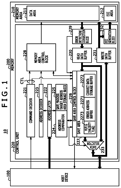
FIG. 1 illustrates an example configuration of a semiconductor device according to a first embodiment. A semiconductor device 1 illustrated in FIG. 1 includes a memory 110, an encoder 120, and a decoder 200.
The memory 110 is a memory circuit that stores data, and may be, for example, a volatile memory such as a dynamic random-access memory (DRAM) and a static RAM (SRAM) or a nonvolatile memory such as a flash memory.
The encoder 120 converts input data Din into encoded data I, and outputs the encoded data I to the memory 110. The encoder 120 generates n-bit encoded data I[(n-1):0], where n is an integer larger than or equal to 4, by making the value of a bit of the input data Din redundant. Herein, the value of each bit of the encoded data I is not predetermined, and is determined in accordance with the value of the input data Din. For example, the encoder 120 outputs the encoded data I that stores the same value as the input data Din in each of the n bits.
The decoder 200 detects errors in the encoded data I output from the memory 110, and outputs output data Dout on the basis of the results of error detection. The decoder 200 detects and corrects a single-bit error, and detects a double-bit error in the encoded data I. The decoder 200 outputs the output data Dout that agrees with the original input data Din at least when no error occurs in any bits of the encoded data I and when an error occurs in a bit of the encoded data I.
Since the decoder 200 corrects a single-bit error, output data Dout having the same value as that of the input data Din is reliably output even if a bit error, i.e., reading of an incorrect value from the memory, occurs in one of the n bits due to, for example, failure of memory cells in the memory 110. That is, recording of the encoded data I, converted from the input data Din by the encoder 120, in the memory 110 and outputting of the output data Dout from the decoder 200 on the basis of the encoded data I read from the memory 110 improve reliability of data written to and read from the memory 110.
The decoder 200 may be provided for another semiconductor device that does not include the memory 110. Similarly, the encoder 120 may be provided for another semiconductor device that does not include the memory 110.
FIG. 2 illustrates an example internal configuration of the decoder. The decoder 200 includes (n-1) 2-bit checking units 210_0 to 210_(n-2), an all-bit checking unit 220, and an error detecting unit 230. Each of the 2-bit checking units 210_0 to 210_(n-2) receives values of two bits of the encoded data I, combinations of the two bits differing for each 2-bit checking unit. Each of the 2-bit checking units 210_0 to 210_(n-2) outputs 2-bit check data based on a result of comparison between the values of the two input bits.
Each of the 2-bit checking units 210_0 to 210_(n-2), for example, outputs a value based on an exclusive OR of the values of the two input bits as 2-bit check data. Alternatively, at least one of the 2-bit checking units 210_0 to 210_(n-2) may output 2-bit check data on the basis of an exclusive OR of the value of one of the two input bits and an inverted value of the other bit. Furthermore, at least one of the 2-bit checking units 210_0 to 210_(n-2) may output an inverted value of the result of an exclusive OR as 2-bit check data.
The all-bit checking unit 220 outputs all-bit check data based on exclusive ORs of all input bits of the encoded data I. The term "exclusive ORs of all bits" herein refers to a sequential operation of exclusive ORs of two values. The sequential operation may be performed by, for example, computing an exclusive OR of a first bit and a second bit, and then computing an exclusive OR of the result and a third bit. The all-bit checking unit 220 outputs, for example, the result of the exclusive ORs of all bits of the encoded data I or an inverted value of the result as all-bit check data.
The error detecting unit 230 detects errors in the encoded data I on the basis of the (n-1) sets of the 2-bit check data output from the 2-bit checking units 210_0 to 210_(n-2) and the all-bit check data output from the all-bit checking unit 220. For example, the error detecting unit 230 may determine the existence of up to two error bits of the encoded data I from the combination of the values of the (n-1) sets of the 2-bit check data. Furthermore, the error detecting unit 230 may determine the occurrence of a single-bit error and the position of the error bit from the combination of the values of the (n-1) sets of the 2-bit check data and the value of the all-bit check data. When a single-bit error is detected, for example, the error detecting unit 230 may output the same value as the original input data Din as the output data Dout on the basis of the values of the bits other than the error bit in the encoded data I.
In addition, the error detecting unit 230 may determine, for example, whether or not the number of error bits is one on the basis of the value of the all-bit check data from the all-bit checking unit 220 if the existence of error bits is detected from the combination of the values of the (n-1) sets of the 2-bit check data. Since it may be determined whether or not the number of error bits is one not from n-bit data including the (n-1) sets of the 2-bit check data and the all-bit check data but from the all-bit check data of one bit in this case, the configuration of circuits for the determination may be simplified, and the scale of the circuits may be reduced.
In this embodiment, n-bit check code C, storing the 2-bit check data output from each of the 2-bit checking units 210_0 to 210_(n-2) and the all-bit check data output from the all-bit checking unit 220 in the order from the lowest bit to the highest, is input to the error detecting unit 230 as illustrated in FIG. 2.
In addition, the error detecting unit 230 outputs an error notification signal ERR indicating whether or not an error occurs and an error notification signal UE indicating whether or not the error is uncorrectable in addition to the output data Dout. A signal processor (not illustrated) that receives the output data Dout from the decoder 200 may recognize that the value of the output data Dout is correct when the error notification signal ERR is "0" that indicates the non-occurrence of errors or when the error notification signal ERR is "1" that indicates the occurrence of errors and the error notification signal UE is "0" that indicates a correctable error, i.e., a single-bit error.
Next, example processes performed by the encoder 120 and the decoder 200 and example internal configurations of related components will be described. As an example, n is 4 in the following description.
Encoding Example 1
FIG. 3 illustrates the relationship between input data and encoded data in Encoding Example 1.
In Encoding Example 1, the same value as the input data Din is stored in each of the four bits of the encoded data I. For example, the encoded data I is "0000" when the input data Din is "0", and the encoded data I is "1111" when the input data Din is "1". Herein, the Hamming distance between the two possible values "0000" and "1111" of the encoded data I is "4". When the Hamming distance is "4", the maximum number of bits whose errors are detectable is 4/2=2, and the maximum number of bits whose errors are correctable is 4/2-1=1. That is, in order to correct a single-bit error, the smallest number n of bits of the encoded data is 4, which allows the Hamming distance to be larger than or equal to 4.
FIG. 4 illustrates an example circuit configuration of an encoder that implements Encoding Example 1.
The encoder 120 illustrated in FIG. 4 includes, for example, a branch circuit 121 that branches the input data Din into four. This allows the encoder 120 to convert data as illustrated in FIG. 3.
Encoding Example 2
FIG. 5 illustrates the relationship between input data and encoded data in Encoding Example 2.
In Encoding Example 2, the same value as the input data Din is stored in the lower two bits of the 4-bit encoded data I, and the inverted value of the input data Din is stored in the upper two bits. For example, the encoded data I is "1100" when the input data Din is "0", and the encoded data I is "0011" when the input data Din is "1". Herein, the Hamming distance between the two possible values "1100" and "0011" of the encoded data I is "4" as in Encoding Example 1.
The encoded data I generated as illustrated in FIG. 5 allows the decoder 200 to correctly detect errors even if, for example, the values in all memory cells in the memory 110 turn into "0" or "1" due to, for example, some failure of the memory 110. In cases where the encoded data I as illustrated in FIG. 3 is generated, for example, it is not determined whether or not the value of the encoded data I is correct when "0000" is read from the memory 110 as the encoded data I. In contrast, in cases where the encoded data I is generated as illustrated in FIG. 5, it is determined that the encoded data I is not correct when the "0000" is read from the memory. Similar effects may be produced when the encoded data I stores the same value as the input data Din in at least one of the four bits and the inverted value of the input data Din in at least one of the four bits.
FIG. 6 illustrates an example circuit configuration of an encoder that implements Encoding Example 2. In FIG. 6, the same reference numerals and symbols are used for components corresponding to those illustrated in FIG. 4.
The encoder 120 illustrated in FIG. 6 includes, for example, the branch circuit 121 that branches the input data Din into four and inverters 122 and 123 each inverting one of the four values output from the branch circuit 121. This allows the encoder 120 to convert data as illustrated in FIG. 5.
Decoding Example 1
FIGS. 7 and 8 illustrate the relationships among input data, check codes, and decoder outputs in Decoding Example 1.
In Decoding Example 1, it is assumed that the encoded data I is generated as in Encoding Example 1 illustrated in FIG. 3. In the example calculation illustrated in FIG. 7, the original input data Din is "0", and the encoded data I generated by the encoder 120 is "0000". Meanwhile, in the example calculation illustrated in FIG. 8, the original input data Din is "1", and the encoded data I generated by the encoder 120 is "1111". In the following description, a symbol "^" indicates an exclusive OR operation, and characters "0x" are the prefix for hexadecimal numbers.
In Decoding Example 1, each of the four bits of the check code C is calculated as follows on the basis of the 4-bit encoded data I input to the decoder 200. Herein, C[0] to C[2] correspond to the 2-bit check data, and C[3] corresponds to the all-bit check data. C[0]=I[0]^I[1]
C[1]=i[1]^i[2]
C[2]=i[2]^i[3]
C[3]=i[0]^i[1]^i[2]^i[3]
As illustrated in FIGS. 7 and 8, the check code C is "0x0" when no bit error occurs in the encoded data I. In contrast, when a single-bit or double-bit error occurs in the encoded data I, the value of the check code C is other than "0x0". This allows the decoder 200 to determine the occurrence of a single-bit or double-bit error from the check code C. The error detecting unit 230 (see FIG. 2) of the decoder 200 sets "0" to the error notification signal ERR when the check code C is "0x0", and sets "1" when the check code C is other than "0x0".
In addition, from Expression (4), the C[3] bit of the check code C indicates the parity of the number of "1" in the encoded data I input to the decoder 200. Therefore, the value of C[3] differs when a single-bit error occurs and when a double-bit error occurs. This allows the decoder 200 to determine whether the detected error is a single-bit error or a double-bit error from the value of C[3] when the error notification signal ERR is "1". The error detecting unit 230 of the decoder 200 sets "0" that indicates correctable errors to the error notification signal UE when the error notification signal ERR is "1" and C[3] is "1", and sets "1" that indicates uncorrectable errors to the error notification signal UE when C[3] is "0".
Furthermore, when a single-bit error occurs in the encoded data I, the value of the check code C varies depending on the position of the error bit as illustrated in FIGS. 7 and 8. This allows the decoder 200 to determine the position of the error bit in the encoded data I from the value of the check code C when a single-bit error occurs.
The decoder 200 sets the value of a bit of the encoded data I, no error occurring in the bit, as the output data Dout on the basis of the result of determination of the error position. In the examples illustrated in FIGS. 7 and 8, the error detecting unit 230 of the decoder 200 sets the value of I[1] bit of the encoded data I as the output data Dout when the check code is "0x9", and sets the value of I[0] bit of the encoded data I as the output data Dout when the check code is other than "0x9".
As illustrated in FIGS. 7 and 8, the above-described relationships between the encoded data I and the check code C hold when the encoded data I generated by the encoder 120 is "0000" or "1111". Therefore, detection of errors in up to two bits and correction of a single-bit error are correctly performed even if the output from the memory cells is changed from "0" to "1" or from "1" to "0" in Decoding Example 1.
FIG. 9 illustrates an example circuit configuration of a decoder that implements Decoding Example 1. The decoder 200 illustrated in FIG. 9 includes XOR (exclusive OR) gates 241 to 244, comparators 245 and 246, inverters 247 and 248, and selectors 249 and 250.
The XOR gates 241 to 243 correspond to, for example, 2-bit checking units 210_0 to 210_2, respectively, among the 2-bit checking units illustrated in FIG. 2. The XOR gates 241 to 243 evaluate Expressions
to (3), respectively. The XOR gate 244 corresponds to the all-bit checking unit 220 illustrated in FIG. 2. The XOR gate 244 evaluates Expression (4).
The comparator 245 and the inverter 247 are circuits that determine the occurrence of errors in the encoded data I. The comparator 245 outputs "1" when the check code C output from XOR gates 241 to 244 is "0x0", and outputs "0" when the check code C is other than "0x0". The inverter 247 inverts the value output from the comparator 245, and outputs the inverted value as the error notification signal ERR.
The comparator 246 and the selector 250 are circuits for outputting the output data Dout on the basis of the check code C. The comparator 246 outputs "1" when the check code C is "0x9", and outputs "0" when the check code C is other than "0x9". The selector 250 selects the value of I[0] or I[1] bit of the encoded data I in accordance with the value output from the comparator 246, and outputs the selected value as the output data Dout. The selector 250 outputs the value of I[1] when the value output from the comparator 246 is "1", and outputs the value of I[0] when the value output from the comparator 246 is "0".
The inverter 248, the selector 249, and the comparator 245 constitute a circuit for generating the error notification signal UE. The inverter 248 inverts the value of C[3] from the XOR gate 244. The selector 249 selects the value of C[3] from the XOR gate 244 or the value output from the inverter 248 in accordance with the value output from the comparator 245, and outputs the selected value as the error notification signal UE. The selector 249 outputs the value of C[3] from the XOR gate 244 when the value output from the comparator 245 is "1", that is, when the check code C is "0x0". When the value output from the comparator 245 is "0", that is, when the check code C is other than "0x0", the selector 249 outputs the value output from the inverter 248.
The circuit configuration as illustrated in FIG. 9 leads to the relationships between the input encoded data I and the values output from the decoder 200 as illustrated in FIGS. 7 and 8.
An example of encoding and decoding when n=3 will now be described for comparison. Herein, the encoded data I is "000" when the input data Din input to the encoder 120 is "0", and the encoded data I is "111" when the input data Din is "1". In this case, the Hamming distance between "000" and "111" is "3", and the maximum number of bits whose errors are correctable is 3/2-1=0.5. Accordingly, a single-bit error is not corrected when n=3. This is clear from example calculations illustrated in FIGS. 10 and 11.
FIGS. 10 and 11 illustrate example calculations by the decoder when n=3.
In the example calculations by the decoder 200 illustrated in FIGS. 10 and 11, C[0] and C[1] of 3-bit check code C are calculated using Expressions
and (2), respectively, and C[2] is calculated using the following Expression (5). C[2]=I[0]^I[1]^I[2]
In the example calculations illustrated in FIGS. 10 and 11, the value of the check code C when a single-bit error occurs becomes the same as that of the check code C when a double-bit error occurs in some cases. For example, the check code C when an error occurs in the I[2] bit is the same as that when two errors occur in the I[0] and I[1] bits. In addition, the value of C[3] when a single-bit error occurs and that when a double-bit error occurs become the same. As a result, single-bit errors and double-bit errors are indiscriminable, and furthermore, the positions of the error bits are not identifiable in the example calculations illustrated in FIGS. 10 and 11. Accordingly, single-bit errors are not correctable in the example calculations illustrated in FIGS. 10 and 11.
Decoding Example 2
FIGS. 12 and 13 illustrate the relationships among input data, check codes, and decoder outputs in Decoding Example 2.
In Decoding Example 2, it is assumed that the encoded data I is generated as in Encoding Example 2 illustrated in FIG. 5. In the example calculation illustrated in FIG. 12, the original input data Din is "0", and the encoded data I generated by the encoder 120 is "1100". In the example calculation illustrated in FIG. 13, the original input data Din is "1", and the encoded data I generated by the encoder 120 is "0011". In Decoding Example 2, the check code C is calculated, as illustrated in FIGS. 12 and 13, using Expressions
to
as in Decoding Example 1.
As in Decoding Example 1, the value of the check code C differs when no bit error occurs in the encoded data I and when a single-bit or double-bit error occurs in the encoded data I in Decoding Example 2. This allows the decoder 200 to determine the occurrence of a single-bit or double-bit error from the check code C. The error detecting unit 230 (see FIG. 2) of the decoder 200 sets the error notification signal ERR to "0" when the check code C is "0x2", and sets the error notification signal ERR to "1" when the check code C is other than "0x2".
In Decoding Example 2, the value of C[3] differs when a single-bit error occurs and when a double-bit error occurs as in Decoding Example 1. This allows the decoder 200 to determine that the detected error is a single-bit error or a double-bit error from the value of C[3] when the error notification signal ERR is "1". In Decoding Example 2, the error notification signal UE is output on the basis of the value of C[3] as in Decoding Example 1.
Furthermore, when a single-bit error occurs in the encoded data I, the value of the check code C varies depending on the position of the error bit in Decoding Example 2 as in Decoding Example 1. This allows the decoder 200 to determine the position of the error bit in the encoded data I from the value of the check code C when a single-bit error occurs.
The decoder 200 sets the value of a bit of the encoded data I, no error occurring in the bit, as the output data Dout on the basis of the result of determination of the error position. In the example illustrated in FIGS. 12 and 13, the error detecting unit 230 of the decoder 200 sets the value of I[1] bit of the encoded data I as the output data Dout when the check code is "0xB", and sets the value of I[0] bit of the encoded data I as the output data Dout when the check code is other than "0xB".
In Decoding Example 2, error detection and correction performed on the basis of the encoded data I generated through the procedure in Encoding Example 2 allows the decoder 200 to correctly detect errors even if, for example, the values in all memory cells in the memory 110 turn into "0" or "1" due to, for example, failure of the memory cells. That is, the input encoded data I is "1100" or "0011" when no error bit exists in Decoding Example 2. If all memory cells in the memory 110 turn into "0" or "1", the input encoded data I will be "0000" or "1111", respectively. This allows the decoder 200 to detect the occurrence of errors.
As illustrated in FIGS. 12 and 13, the above-described relationships between the encoded data I and the check code C hold when the encoded data I generated by the encoder 120 is "1100" or "0011". Therefore, detection of errors in up to two bits and correction of a single-bit error are also correctly performed even if the output from the memory cells is changed from "0" to "1" or from "1" to "0" in Decoding Example 2.
FIG. 14 illustrates an example circuit configuration of a decoder that implements Decoding Example 2. In FIG. 14, the same reference numerals and symbols are used for components corresponding to those illustrated in FIG. 9. The decoder 200 illustrated in FIG. 14 is similar to the decoder 200 illustrated in FIG. 9 except for including comparators 251 and 252 instead of the comparators 245 and 246.
The comparator 251 outputs "1" when the check code C output from the XOR gates 241 to 244 is "0x2", and outputs "0" when the check code C is other than "0x2". As a result, the error notification signal ERR becomes "0" when the check code C is "0x2", and becomes "1" when the check code C is other than "0x2". The selector 249 outputs the value of C[3] from the XOR gate 244 when the value output from the comparator 251 is "1", that is, when the check code C is "0x2". When the value output from the comparator 251 is "0", that is, when the check code C is other than "0x2", the selector 249 outputs the value output from the inverter 248.
The comparator 252 outputs "1" when the check code C is "0xB", and outputs "0" when the check code C is other than "0xB". As a result, the selector 250 outputs the value of I[1] when the value output from the comparator 252 is "1", that is, when the check code C is "0xB" while outputting the value of I[0] when the value output from the comparator 252 is "0", that is, when the check code C is other than "0xB".
The circuit configuration as illustrated in FIG. 14 leads to the relationships between the input encoded data I and the values output from the decoder 200 as illustrated in FIGS. 12 and 13.
Decoding Example 3
FIGS. 15 and 16 illustrate the relationships among input data, check codes, and decoder outputs in Decoding Example 3.
In Decoding Example 3, it is assumed that the encoded data I is generated as in Encoding Example 1 illustrated in FIG. 3. In the example calculation illustrated in FIG. 15, the original input data Din is "0", and the encoded data I generated by the encoder 120 is "0000". In the example calculation illustrated in FIG. 16, the original input data Din is "1", and the encoded data I generated by the encoder 120 is "1111".
In Decoding Examples 1 and 2, the value of the 4-bit check code C is compared with a predetermined value so that signals to be output from the decoder 200 are generated. In contrast, a computational expression for check code generation is selected in Decoding Example 3 so that comparison with the 4-bit value is performed only one time. This may reduce processing loads on the decoder 200, and may reduce the scale of the circuits.
In Decoding Example 3, each of the four bits of the check code C is calculated as below on the basis of the encoded data I input to the decoder 200. Herein, a symbol ".about." indicates an inversion (negation) operation. C[0]=.about.(I[0]^I[1])
C[1]=.about.(I[0]^I[2])
C[2]=.about.(I[1]^I[2])
C[3]=.about.(I[0]^I[1]^I[2]^I[3])
In Decoding Example 3, the value of the check code C differs when no bit error occurs in the encoded data I and when a single-bit or double-bit error occurs in the encoded data I as in Decoding Examples 1 and 2. This allows the decoder 200 to determine the occurrence of a single-bit or double-bit error from the check code C. The error detecting unit 230 (see FIG. 2) of the decoder 200 sets the error notification signal ERR to "0" when the check code C is "0xF", and sets the error notification signal ERR to "1" when the check code C is other than "0xF".
In Decoding Example 3, the value of C[3] differs when a single-bit error occurs and when a double-bit error occurs as in Decoding Examples 1 and 2. This allows the decoder 200 to determine that the detected error is a single-bit error or a double-bit error from the value of C[3] when the error notification signal ERR is "1". In Decoding Example 3, the error notification signal UE is output on the basis of the value of C[3] as in Decoding Examples 1 and 2.
Furthermore, when a single-bit error occurs in the encoded data I, the value of the check code C varies depending on the position of the bit error in Decoding Example 3 as in Decoding Examples 1 and 2. This allows the decoder 200 to determine the position of the error bit in the encoded data I from the value of the check code C when a single-bit error occurs.
The decoder 200 sets the value of a bit of the encoded data I, no error occurring in the bit, as the output data Dout on the basis of the result of determination of the error position. In Decoding Example 3, the source of the output data Dout is selected on the basis of the value of one of C[0] to C[2] bits unlike Decoding Examples 1 and 2. In the examples illustrated in FIGS. 15 and 16, the error detecting unit 230 of the decoder 200 sets the value of I[1] as the output data Dout when C[2] is "1", and sets the value of I[0] as the output data Dout when C[2] is "0".
As illustrated in FIGS. 15 and 16, the above-described relationships between the encoded data I and the check code C hold when the encoded data I generated by the encoder 120 is "0000" or "1111". Therefore, detection of errors in up to two bits and correction of a single-bit error are also correctly performed even if the output from the memory cells is changed from "0" to "1" or from "1" to "0" in Decoding Example 3.
FIG. 17 illustrates an example circuit configuration of a decoder that implements Decoding Example 3. In FIG. 17, the same reference numerals and symbols are used for components corresponding to those illustrated in FIG. 9. The decoder 200 illustrated in FIG. 17 is similar to the decoder 200 illustrated in FIG. 9 except for not including the comparator 246 and including inverters 261 to 264. The decoder 200 illustrated in FIG. 17 also includes a comparator 265 instead of the comparator 245 illustrated in FIG. 9. Furthermore, the combinations of signals input to the XOR gates 242 and 243 and the source of a selection control signal to the selector 250 differ from those in the decoder 200 illustrated in FIG. 9.
The values of I[0] and I[2] bits of the encoded data I are input to the XOR gate 242, and the values of I[1] and I[2] bits of the encoded data I are input to the XOR gate 243. The inverters 261 to 264 invert the values output from the XOR gates 241 to 244, respectively. The values output from the inverters 261 to 264 correspond to C[0] to C[3], respectively.
The comparator 265 outputs "1" when the check code C output from the inverters 261 to 264 is "0xF", and outputs "0" when the check code C is other than "0xF". The inverter 247 inverts the value output from the comparator 265, and outputs the inverted value as the error notification signal ERR.
The selector 249 receives a signal output from the comparator 265 as a selection control signal. The selector 249 outputs C[3] from the inverter 264 as the error notification signal UE when the value output from the comparator 265 is "1", and outputs the value output from the inverter 248 as the error notification signal UE when the value output from the comparator 265 is "0".
The selector 250 receives C[2] from the inverter 263 as the selection control signal. The selector 250 outputs the value of I[1] as the output data Dout when C[2] is "1", and outputs the value of I[0] when C[2] is "0".
The circuit configuration as illustrated in FIG. 17 leads to the relationships between the input encoded data I and the values output from the decoder 200 as illustrated in FIGS. 15 and 16. Although the inverters 261 to 264 are added, the circuit configuration illustrated in FIG. 17 does not need the comparators 246 and 252 for comparing the values of four bits illustrated in, for example, FIGS. 9 and 14, respectively. This may reduce the entire circuit scale.
The scale of the circuits may also be reduced when other computational methods are used instead of the method of computing the check code C used in Decoding Example 3. That is, the scale of the circuits may be reduced by adopting a method of computing C[0] to C[2] such that a bit, no error occurring in the bit, of the encoded data I is selected in accordance with one of the values of C[0] to C[2]. The method of computing C[0] to C[2] may be changed by, for example, changing the combinations of bits of the encoded data I to be subjected to exclusive OR operations, changing the results of exclusive OR operations (C[0] to C[2]) to be inverted, and computing exclusive ORs of two bits of the encoded data I after either or both of the two bits are inverted.
Example of Symbol-by-Symbol Encoding and Decoding
In addition to bit-by-bit error detection and correction of the input data Din described in the encoding and decoding examples above, errors may also be detected and corrected multiple bits at a time. As an example, symbol-by-symbol error detection and correction, eight bits for one 8-bit symbol, will be described below.
FIG. 18 illustrates an example of symbol-by-symbol encoding.
In the example illustrated in FIG. 18, an 8-bit symbol of the input data Din is converted into 32-bit encoded data I by the encoder 120. The encoded data I consists of I0 to I3 in the order from the lowest bit to the highest, and each of I0 to I3 consists of eight bits. In the example illustrated in FIG. 18, the value of each bit of the symbol of the input data Din is stored in the I0 and I1 without being changed while an inverted value is stored in I2 and I3. This encoding process may be performed by, for example, the encoder 120 having the configuration illustrated in FIG. 6. In this case, the encoder 120 illustrated in FIG. 6 outputs I0 to I3 instead of I[0] to I[3].
I0 to I3 of the encoded data I generated by this process are decoded by the decoder 200. The decoding process may be performed as is the bit-by-bit decoding process. For example, C[0] to C[3] of the check code C are calculated by substituting I0 to I3 for I[0] to I[3] in Expressions
to (4), Expressions (1), (2), (5), and (4), or Expressions
to (9), respectively. When C[0] to C[3] are calculated using Expressions
to (4), respectively, the decoder 200 may have a configuration as illustrated in, for example, FIG. 9. In this case, the decoder 200 illustrated in FIG. 9 receives I0 to I3 instead of I[0] to I[3].
FIG. 19 illustrates examples of bit error patterns of encoded data encoded a symbol at a time. FIG. 19 illustrates the examples of the bit error patterns when "0x00" serving as the input data Din is encoded. I0 to I3 each consist of eight bits, and each of the eight bits is referred to as a "zeroth bit", a "first bit", . . . , and a "seventh bit" from the lowest.
Bit error pattern 1 indicates a case where bit errors occur in all bits of one of I0 to I3. In the bit error pattern 1 illustrated in FIG. 19, bit errors occur in all bits of I3. In the decoder 200, error detection and correction is performed for each set of bits of I0 to I3 in the same bit position, that is, for each set of the zeroth bits, the first bits, . . . , and the seventh bits. Therefore, when bit errors occur in all bits of I3 as in the bit error pattern 1, the decoder 200 determines that single-bit errors occur in all eight bit positions of I0 to I3. Since the decoder 200 corrects single-bit errors, the decoder 200 correctly outputs "0x00" as the output data Dout when bit errors as illustrated in the bit error pattern 1 occur.
Bit error pattern 2 illustrated in FIG. 19 indicates a case where only one bit error occurs in each set of the bits of I0 to I3 in the same bit position although bit errors occur in multiple bits of the encoded data I. In the bit error pattern 2 illustrated in FIG. 19, bit errors occur in the third and seventh bits of I0, the second and sixth bits of I1, the first and fifth bits of I2, and the zeroth and fourth bits of I3. In this case, the decoder 200 determines that single-bit errors occur in all eight bit positions of I0 to I3, and correctly outputs "0x00" as the output data Dout.
Bit error pattern 3 illustrated in FIG. 19 indicates a case where bit errors occur in all bits of two of I0 to I3. In the bit error pattern 3 illustrated in FIG. 19, bit errors occur in all bits of I2 and I3. In this case, the decoder 200 detects double-bit errors in all eight bit positions of I0 to I3. However, there is no guarantee that the output data Dout agrees with the original input data Din.
The description continues in the full USPTO document.
 Lapsed, fee not paid9 drawings