Cross-reference to related applications
This application is based on and claims priority under 35 USC 119 from Japanese Patent Application No. 2011-166388 filed Jul. 29, 2011.
Background
Technical Field
The present invention relates to a medium feeding device and an image forming apparatus.
Summary
According to an aspect of the invention, there is provided a medium feeding device including a loading member on which mediums are stacked; a holding member that includes a holding-member body that faces the loading member and is supported in such a manner as to be movable in a medium transport direction, the holding-member body having a gas suction opening, and a suction device that is connected to the gas suction opening and performs suction of gas, the holding member being configured to attract and hold each of the mediums while suction is performed by the suction device; a holding-member-moving mechanism that faces the loading member and moves the holding member between a suction position where each of the mediums on the loading member is attracted to the holding member and a feed position defined on a downstream side in the medium transport direction with respect to the suction position; a transport member that transports the medium held by the holding member that is at the feed position toward the downstream side; and a suction-force-changing mechanism that changes a suction force with which the medium is attracted to the holding member, the suction force being reduced after the medium is attracted to the holding member and before a trailing end, in the medium transport direction, of the medium attracted to the holding member passes over the gas suction opening.
Brief description of the drawings
Exemplary embodiments of the present invention will be described in detail based on the following figures, wherein:
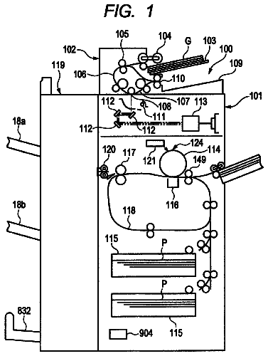
FIG. 1 illustrates the entirety of an image forming apparatus according to a first exemplary embodiment of the present invention;
FIG. 2 illustrates a feed tray according to the first exemplary embodiment;
FIG. 3 is a plan view of the feed tray according to the first exemplary embodiment;
FIGS. 4A and 4B illustrate a loading plate according to the first exemplary embodiment at a lowered position and at a lifted position, respectively;
FIGS. 5A and 5B are a front view and a plan view, respectively, of a suction head according to the first exemplary embodiment;
FIG. 6 is a bottom perspective view of the suction head according to the first exemplary embodiment;
FIG. 7 is a sectional view of the suction head taken along line VII-VII illustrated in FIG. 5B;
FIGS. 8A and 8B illustrate the suction head according to the first exemplary embodiment at a suction position and at a feed position, respectively;
FIGS. 9A to 9C illustrate a suction port shutter according to the first exemplary embodiment as a plan view illustrating the suction port shutter seen from above inside the suction head, as a sectional view taken along line IXB-IXB illustrated in FIG. 9A, and as a view seen in a direction of arrow IXC illustrated in FIG. 9A, respectively;
FIGS. 10A to 10C illustrate the suction port shutter according to the first exemplary embodiment at an open position, at a half shut position, and at a fully shut position, respectively;
FIG. 11A illustrates a state of the feed tray before a job is started;
FIG. 11B illustrates a state of the feed tray after a job has been started and the loading plate has been moved to the lifted position from the state illustrated in FIG. 11A;
FIG. 12A illustrates a state where plural sheets have been attracted to the suction head at the activation of an exhaust fan after the state illustrated in FIG. 11B, and air is blown toward the sheets by an air blowing mechanism so that the sheets are separated from one another;
FIG. 12B illustrates a state where the suction head has been moved from the position illustrated in FIG. 12A to the feed position;
FIGS. 13A to 13C are sectional views illustrating the suction head according to the first exemplary embodiment in a state where a leading end guide has reached transport rollers after the state illustrated in FIG. 12A, in a state where the sheet has reached the transport rollers after the state illustrated in FIG. 13A, and in a state where the suction head has been moved to the feed position, illustrated in FIG. 12B, after the state illustrated in FIG. 13B, respectively;
FIGS. 14A to 14C correspond to FIGS. 9A to 9C illustrating the first exemplary embodiment, and are a plan view of a suction port shutter according to a second exemplary embodiment of the present invention seen from above inside the suction head, a sectional view taken along line XIVB-XIVB illustrated in FIG. 14A, and a perspective view of a rack and a pinion, respectively;
FIGS. 15A to 15C correspond to FIGS. 10A to 10C illustrating the first exemplary embodiment, and illustrate the suction port shutter according to the second exemplary embodiment at an open position, at a half shut position, and at a fully shut position, respectively;
FIG. 16 is a block diagram illustrating functions of a controller of the image forming apparatus according to the second exemplary embodiment;
FIG. 17 is a flowchart of a sheet feeding operation according to the second exemplary embodiment;
FIGS. 18A to 18C correspond to FIGS. 13A to 13C illustrating the first exemplary embodiment, and are sectional views illustrating the suction head according to the second exemplary embodiment in a state where the leading end guide has reached the transport rollers, in a state where the sheet has reached the transport rollers after the state illustrated in FIG. 18A, and in a state where the suction head has been moved to the feed position after the state illustrated in FIG. 18B, respectively;
FIGS. 19A to 19C correspond to FIGS. 9A to 9C illustrating the first exemplary embodiment, and illustrate a connection-and-separation mechanism according to a third exemplary embodiment of the present invention as a plan view illustrating an exhaust duct seen from above inside the suction head, as a sectional view taken along line XIXB-XIXB illustrated in FIG. 19A, and as a front view of the connection-and-separation mechanism, respectively;
FIGS. 20A to 20C correspond to FIGS. 10A to 10C illustrating the first exemplary embodiment, and illustrate an exhaust port according to the third exemplary embodiment at a fully connected position, at a half connected position, and at a separated position, respectively;
FIGS. 21A to 21C correspond to FIGS. 13A to 13C illustrating the first exemplary embodiment, and are sectional views illustrating the suction head according to the third exemplary embodiment in a state where the leading end guide has reached the transport rollers, in a state where the sheet has reached the transport rollers after the state illustrated in FIG. 21A, and in a state where the suction head has reached the feed position after the state illustrated in FIG. 21B, respectively;
FIGS. 22A and 22B correspond to FIGS. 14B and 14C illustrating the second exemplary embodiment, and illustrate an opening-and-closing mechanism according to a fourth exemplary embodiment of the present invention as a view seen from the rear inside the suction head and as a perspective view illustrating a rack and a pinion, respectively;
FIGS. 23A to 23C correspond to FIGS. 15A to 15C illustrating the second exemplary embodiment, and illustrate an exhaust port shutter according to the fourth exemplary embodiment at an open position, at a half shut position, and at a fully shut position, respectively;
FIG. 24 corresponds to FIG. 16 illustrating the second exemplary embodiment and is a block diagram illustrating controller of the image forming apparatus according to the fourth exemplary embodiment;
FIG. 25 corresponds to FIG. 17 illustrating the second exemplary embodiment and is a flowchart of a sheet feeding operation according to the fourth exemplary embodiment;
FIGS. 26A to 26C correspond to FIGS. 13A to 13C illustrating the first exemplary embodiment, and are sectional views illustrating the suction head according to the fourth exemplary embodiment in a state where the leading end guide has reached the transport rollers, in a state where the sheet has reached the transport rollers after the state illustrated in FIG. 26A, and in a state where the suction head has been moved to the feed position after the state illustrated in FIG. 26B, respectively;
FIGS. 27A to 27C correspond to FIGS. 23A to 23C illustrating the fourth exemplary embodiment, and illustrate an opening shutter according to a fifth exemplary embodiment of the present invention at a shut position, at a half open position, and at a fully open position, respectively;
FIG. 28 corresponds to FIG. 24 illustrating the fourth exemplary embodiment and is a block diagram illustrating a controller of the image forming apparatus according to the fifth exemplary embodiment;
FIGS. 29A to 29C correspond to FIGS. 26A to 26C illustrating the fourth exemplary embodiment, and are sectional views illustrating the suction head according to the fifth exemplary embodiment in a state where the leading end guide has reached the transport rollers, in a state where the sheet has reached the transport rollers after the state illustrated in FIG. 29A, and in a state where the suction head has been moved to the feed position after the state illustrated in FIG. 29B, respectively;
FIG. 30 corresponds to FIG. 5B illustrating the first exemplary embodiment and is a plan view of a suction head according to a sixth exemplary embodiment of the present invention;
FIG. 31 corresponds to FIG. 16 illustrating the second exemplary embodiment and is a block diagram illustrating a controller of the image forming apparatus according to the sixth exemplary embodiment;
FIG. 32 corresponds to FIG. 17 illustrating the second exemplary embodiment and is a flowchart of a sheet feeding operation according to the sixth exemplary embodiment; and
FIGS. 33A to 33C correspond to FIGS. 18A to 18C illustrating the second exemplary embodiment, and are sectional views illustrating the suction head according to the sixth exemplary embodiment in a state where the leading end guide has reached the transport rollers, in a state where the sheet has reached the transport rollers after the state illustrated in FIG. 33A, and in a state where the suction head has reached the feed position after the state illustrated in FIG. 33B, respectively.
Detailed description
Exemplary embodiments of the present invention will now be described with reference to the accompanying drawings. Note that the invention is not limited to the following exemplary embodiments.
For ease of understanding of the following description, directions in the drawings are defined as follows: the anteroposterior direction is represented by the X axis, the lateral direction is represented by the Y axis, and the vertical direction is represented by the Z axis. Furthermore, arrows X, -X, Y, -Y, Z, and -Z represent the directions toward the front, the rear, the right, the left, the top, and the bottom, respectively. Furthermore, in the drawings, the encircled dot represents an arrow extending from the back side toward the front side of the page, and the encircled cross represents an arrow extending from the front side toward the back side of the page.
In the following description and the drawings referred to therein, descriptions and illustrations of irrelevant elements are omitted for ease of understanding.
First Exemplary Embodiment
FIG. 1 illustrates the entirety of an image forming apparatus U according to a first exemplary embodiment of the present invention.
Referring to FIG. 1, the image forming apparatus U includes a user interface UI as an exemplary operation unit, an image scanner U1 as an exemplary image-information-inputting device, a sheet feeding device U2 as an exemplary medium feeding device, an image-forming-apparatus body U3, and a sheet processing device U4.
The user interface UI includes input keys as exemplary input members, such as a copy start key, a key for setting the number of copies, a numeric keypad, and so forth, and a display UI1.
The image scanner U1 includes an automatic document transport device that automatically transports each page of a document, a scanner body as an exemplary image reading device, and so forth. Referring to FIG. 1, the image scanner U1 reads each page of the document (not illustrated), converts the read data into image information, and inputs the image information to the image-forming-apparatus body U3.
The sheet feeding device U2 is an exemplary storage container and includes plural feed trays TR1 and TR2 as exemplary feeders, a feed path SH1 as an exemplary transport path along which each sheet S as an exemplary medium that is fed from one of the feed trays TR1 and TR2 is transported to the image-forming-apparatus body U3, and so forth.
Referring to FIG. 1, the image-forming-apparatus body U3 includes an image recording section that records an image on the sheet S transported from the sheet feeding device U2, a toner dispenser device U3a as an exemplary developer supplying unit, a sheet transport path SH2, a sheet output path SH3, a sheet reversal path SH4, a sheet circulation path SH6, and so forth. The image recording section will be described separately below.
The image-forming-apparatus body U3 further includes a controller C, a laser driving circuit D as an exemplary driving circuit for latent image writing that is controlled by the controller C, a power circuit E controlled by the controller C, and so forth. The laser driving circuit D controlled by the controller C outputs, at preset timings, laser driving signals corresponding to pieces of image information on respective colors of yellow (Y), magenta (M), cyan (C), and black (K) that are input thereto from the image scanner U1 to respective latent-image-forming devices ROSy, ROSm, ROSc, and ROSk provided for the foregoing colors.
Referring to FIG. 1, an image carrier unit UK for the K color includes a photoconductor Pk as an exemplary image carrier, a charger CCk as an exemplary discharger, and a photoconductor cleaner CLk as an exemplary image carrier cleaner. Image carrier units UY, UM, and UC for the other M, and C colors also include respective photoconductors Py, Pm, and Pc, respective chargers CCy, CCm, and CCc, and respective photoconductor cleaners CLy, CLm, and CLc. In the first exemplary embodiment, the photoconductor Pk for the K color is used more frequently and the surface thereof wears more than others. Therefore, the photoconductor Pk has a larger diameter, is capable of rotating at a higher speed, and has a longer life than the photoconductors Py, Pm, and Pc for the other colors.
The image carrier units UY, UM, UC, and UK and development units GY, GM, GC, and GK each including a development roller R0 together form toner-image-forming members "UY and GY", "UM and GM", "UC and GC", and "UK and GK".
Referring to FIG. 1, the photoconductors Py, Pm, Pc, and Pk are evenly charged by the respective chargers CCy, CCm, CCc, and CCk. Subsequently, electrostatic latent images are formed on the surfaces of the respective photoconductors Py, Pm, Pc, and Pk with laser beams Ly, Lm, Lc, and Lk as exemplary latent-image-writing light emitted from the respective latent-image-forming devices ROSy, ROSm, ROSc, and ROSk. The electrostatic latent images on the photoconductors Py, Pm, Pc, and Pk are developed into toner images as exemplary visible images in colors of yellow (Y), magenta (M), cyan (C), and black (K) by the respective development units GY, GM, GC, and GK.
The toner images on the photoconductors Py, Pm, Pc, and Pk are first-transferred onto an intermediate transfer belt B as an exemplary intermediate transfer member in such a manner as to be sequentially superposed one on top of another by first transfer rollers T1y, T1m, T1c, and T1k as exemplary first transfer members, whereby a multi-color image, i.e., a color image, is formed on the intermediate transfer belt B. The color image on the intermediate transfer belt B is transported to a second transfer area Q4 as an exemplary image recording area.
If the image data only includes data on the black (K) color, only the photoconductor Pk and the development unit GK are used, whereby a black toner image is formed.
After the first transfer, toners remaining on the surfaces of the photoconductors Py, Pm, Pc, and Pk are removed by the respective photoconductor cleaners CLy, CLm, CLc, and CLk.
A belt module BM as an exemplary intermediate transfer device is provided below the image carrier units UY, UM, UC, and UK. The belt module BM includes the intermediate transfer belt B as an exemplary intermediate transfer member, belt supporting rollers Rd, Rt, Rw, Rf, and T2a as exemplary intermediate-transfer-member-supporting members, and the first transfer rollers T1y, T1m, T1c, and T1k. The belt supporting rollers Rd, Rt, Rw, Rf, and T2a are specifically a belt driving roller Rd as an exemplary driving member, a tension roller Rt as an exemplary tension applying member, a working roller Rw as an exemplary meandering prevention member, plural idler rollers Rf as exemplary follower members, and a backup roller T2a as an exemplary second-transfer counter member. The intermediate transfer belt B is supported by the belt supporting rollers Rd, Rt, Rw, Rf, and T2a in such a manner as to be rotatable in a direction of arrow Ya.
A second transfer unit Ut is provided below the backup roller T2a. The second transfer unit Ut includes a second transfer roller T2b as an exemplary second transfer member. The second transfer roller T2b is movable in such a manner as to be pressed against and to be brought away from the backup roller T2a with the intermediate transfer belt B interposed therebetween. An area where the second transfer roller T2b is pressed against the intermediate transfer belt B forms the second transfer area Q4. A contact roller T2c as an exemplary voltage-applying contact member is provided in contact with the backup roller T2a. The rollers T2a to T2c together form a second transfer device T2.
The power circuit E controlled by the controller C applies a second transfer voltage with the same polarity as the toner to the contact roller T2c at a predetermined timing.
The sheet transport path SH2 runs below the belt module BM. The sheet S fed from the sheet feeding device U2 along the feed path SH1 is transported into the sheet transport path SH2 by transport rollers Ra as exemplary transport members. And the sheet S is further transported by registration rollers Rr as exemplary transport-timing-adjusting members through a sheet guiding member SGr and a pre-transfer sheet guiding member SG1 to the second transfer area Q4 in accordance with a timing at which a set of toner images is transported to the second transfer area Q4. The set of toner images on the intermediate transfer belt B is second-transferred to the sheet S by the second transfer device T2 when passing through the second transfer area Q4. In the case of a full-color image, toner images that have been first-transferred to the intermediate transfer belt B in such a manner as to be superposed one on top of another are second-transferred to the sheet S at a time.
The intermediate transfer belt B after the second transfer is cleaned by a belt cleaner CLB as an exemplary intermediate-transfer-member cleaner. The second transfer roller T2b is supported in such a manner as to be pressed against and to be brought away from the intermediate transfer belt B.
The first transfer rollers T1y, T1m, T1c, and T1k, the intermediate transfer belt B, the second transfer device T2, the belt cleaner CLB, and other associated elements together form a transfer device "T1, B, T2, and CLB" that transfers images formed on the photoconductors Py, Pm, Pc, and Pk to the sheet S.
The photoconductors Py, Pm, Pc, and Pk, the development units GY, GM, GC, and GK, the transfer device T1, B, T2, and CLB, and other associated elements together form a printer section U3b as an exemplary image recording device according to the first exemplary embodiment.
The sheet S on which the toner images are second-transferred is transported to a fixing device F through a post-transfer sheet guiding member SG2 and a sheet transport belt BH as an exemplary pre-fixing medium transport member. The fixing device F includes a heat roller Fh as an exemplary thermal fixing member and a pressure roller Fp as an exemplary pressure fixing member. A fixing area Q5 is formed in an area where the heat roller Fh and the pressure roller Fp are pressed against each other.
The set of toner images on the sheet S is thermally fixed by the fixing device F when passing through the fixing area Q5. A first gate GT1 as an exemplary transport-path-switching member is provided on the downstream side with respect to the fixing device F. The first gate GT1 switches the path of the sheet S transported along the sheet transport path SH2 and subjected to thermal fixing in the fixing area Q5, between the sheet output path SH3 in the sheet processing device U4 and the sheet reversal path SH4. The sheet S transported into the sheet output path SH3 is transported into a sheet transport path SH5 in the sheet processing device U4.
A decurling device U4a as an exemplary bend straightening device is provided in the sheet transport path SH5. A decurling-direction-switching gate G4 as an exemplary transport-path-switching member is also provided in the sheet transport path SH5. The decurling-direction-switching gate G4 switches the destination of the sheet S transported from the sheet output path SH3 in the image-forming-apparatus body U3, between a first decurling member h1 and a second decurling member h2 in accordance with the direction of bend, i.e., curl of the sheet S. The sheet S transported to the first decurling member h1 or the second decurling member h2 has the curl thereof straightened when passing therethrough. The sheet S whose curl has been straightened is transported by sheet output rollers Rh as exemplary sheet output members. And the sheet S is output face-up, with the side thereof having the fixed image facing upward, onto a sheet output tray TH1 as an exemplary medium output portion of the sheet processing device U4.
The sheet S directed by the first gate GT1 toward the sheet reversal path SH4 in the image-forming-apparatus body U3 pushes away and passes through a second gate GT2 as an exemplary redirecting member made of an elastic thin film, and then, the sheet S is transported into the sheet reversal path SH4 in the image-forming-apparatus body U3.
The downstream end of the sheet reversal path SH4 in the image-forming-apparatus body U3 is connected to the sheet circulation path SH6 and a sheet reversal path SH7. A third gate GT3 as an exemplary redirecting member is provided at the connection between the path SH4 and the paths SH6 and SH7. The sheet S transported through the first gate GT1 into the sheet reversal path SH4 passes through the third gate GT3 into the sheet reversal path SH7 in the sheet processing device U4. In the case of duplex printing, the sheet S transported along the sheet reversal path SH4 passes through the third gate GT3 into the sheet reversal path SH7 and is transported backward, i.e.; switched back, into the sheet circulation path SH6 by being redirected at the third gate GT3. The sheet S transported into the sheet circulation path SH6 is then transported along the feed path SH1 to the second transfer area Q4 again.
If the sheet S that is to be transported in the sheet reversal path SH4 is switched back after the trailing end thereof in a sheet transport direction as an exemplary medium transport direction has passed the second gate GT2 but before the trailing end thereof passes through the third gate GT3, the sheet S is redirected by the second gate GT2 in such a manner as to be turned upside down and to be transported into the sheet transport path SH5. The sheet S turned upside down has the curl thereof straightened by the decurling device U4a and is output facedown, with the side thereof having the fixed image facing downward, onto the sheet output tray TH1 of the sheet processing device U4.
The elements denoted by reference numerals SH1 to SH7 together form a sheet transport path SH. The elements denoted by reference numerals SH, Ra, Rr, Rh, SGr, SG1, SG2, BH, and GT1. GT2, and GT3, and other associated elements together form a sheet transport system SU.
FIG. 2 illustrates one of the feed trays TR1 and TR2, according to the first exemplary embodiment.
Herein, the feed trays TR1 and TR2 according to the first exemplary embodiment will be described in detail focusing on a second feed tray TR2. A first feed tray TR1 has the same configuration as the second feed tray TR2, and detailed description of the first feed tray TR1 is therefore omitted.
Referring to FIG. 2, the second feed tray TR2 has rails 1 as exemplary guiding members at outer left and right ends thereof, respectively. The rails 1 extend in the anteroposterior direction along the X axis. Rollers 2 as exemplary rotary members are rotatably provided on the undersides of the rails 1: The tops of the rollers 2 project upward from holes provided in the undersides of the rails 1.
The feed tray TR2 also has guided rails 3 as exemplary guided members projecting outward from lower left and right ends thereof, respectively. The guided rails 3 extend in the anteroposterior direction. The guided rails 3 are supported at the tops of the rollers 2 provided on the undersides of the rails 1. Thus, the feed tray TR2 is drawable from and insertable into the sheet feeding device U2 in the anteroposterior direction along the left and right rails 1. That is, the feed tray TR2 is movable between a drawn position at which the feed tray TR2 is out of the sheet feeding device U2 and an inserted position at which the feed tray TR2 is in the sheet feeding device U2.
FIG. 3 is a plan view of the feed tray TR2 according to the first exemplary embodiment.
Referring to FIGS. 2 and 3, the feed tray TR2 includes a bottom plate 4 and front, rear, left and right walls 6, 7, 8, and 9 that extend upward from the front, rear, left, and right ends, respectively, of the bottom plate 4. Referring to FIG. 3, an end guide groove 4a as an exemplary first guide portion is provided in left part of the bottom plate 4 of the feed tray TR2 in such a manner as to extend in the lateral direction. Side guide grooves 4b as exemplary second guide portions are provided in right part of the bottom plate 4 in such a manner as to extend in the anteroposterior direction. Referring to FIGS. 2 and 3, the upper end of the right wall 9 forms a sloping portion 9a that extend upward while sloping rightward. The sloping portion 9a guides the sheet S to be fed toward associated ones of the transport rollers Ra.
FIGS. 4A and 4B illustrate a loading plate 11 according to the first exemplary embodiment. In FIG. 4A, the loading plate 11 is at a lowered position. In FIG. 4B, the loading plate 11 is at a lifted position.
The loading plate 11, which is a flat plate and is an exemplary loading member, is provided on the upper surface of the bottom plate 4. Sheets S are stacked on the loading plate 11. The loading plate 11 has a left opening 11a extending from the left end thereof toward the center, and front and rear openings 11b and 11c extending from the front and rear ends thereof, respectively, toward the center. The left opening 11a corresponds to the end guide groove 4a. The front and rear openings 11b and 11c correspond to the side guide grooves 4b. The loading plate 11 according to the first exemplary embodiment is liftable and lowerable by a lifting-and-lowering mechanism SK as an exemplary loading-member-moving mechanism. The lifting-and-lowering mechanism SK employs wires (not illustrated) as exemplary wire members for the lifting-and-lowering movement. Thus, the loading plate 11 is liftable and lowerable between the lowered position as an exemplary retracted position illustrated in FIG. 4A where sheets S are stackable on the loading plate 11 and the lifted position as an exemplary suction position illustrated in FIG. 4B where the sheets S are each fed from the loading plate 11. The lifting-and-lowering mechanism SK employing the wires may be based on a related-art technique, and related-art configurations are applicable thereto Hence, detailed description of the lifting-and-lowering mechanism SK is omitted.
The end guide groove 4a supports an end guide 12 as an exemplary first alignment member. The end guide 12 is movable in the lateral direction along the end guide groove 4a. The end guide 12 includes a slide portion 12a and an alignment contact portion 12b. The slide portion 12a, which is an exemplary alignment member body, is a flat plate and extends along the bottom plate 4. The alignment contact portion 12b extends upward from the left end of the slide portion 12a. Thus, the end guide 12 has a substantially L shape when seen from the front. The right side face of the alignment contact portion 12b forms a contact surface 12c that is to come into contact with the left ends of the sheets S stacked on the loading plate 11. When the contact surface 12c comes into contact with the left ends of the sheets S, the left ends of the sheets S are aligned.
The side guide grooves 4b support a pair of front and rear side guides 13 as exemplary second alignment members, respectively. The side guides 13 are movable in the anteroposterior direction along the respective side guide grooves 4b. The pair of side guides 13 are movable together toward and away from each other with the aid of racks and pinions (not illustrated) as exemplary gears. The racks each include a flat plate having gears. Such a mechanism of moving the side guides 13 together toward and away from each other with the aid of racks and pinions may be based on a related-art technique, and related-art configurations are applicable thereto. Hence, detailed description of the mechanism is omitted.
FIGS. 5A and 5B are a front view and a plan view, respectively, of a suction head 22 according to the first exemplary embodiment.
FIG. 6 is a bottom perspective view of the suction head 22 according to the first exemplary embodiment.
FIG. 7 is a sectional view of the suction head 22 taken along line VII-VII illustrated in FIG. 5B.
Referring to FIGS. 2 and 4A to 7, a sheet pickup device 21 as an exemplary medium pickup member is provided above the feed tray TR2. The sheet pickup device 21 includes the suction head 22 as an exemplary holding member. The suction head 22 attracts and holds one of the sheets S on the loading plate 11 by suction.
The suction head 22 includes a box-shaped head body 23 as an exemplary holding-member body. The head body 23 includes a bottom plate 24, which has a flat shape, and sidewalls 26, 27, 28, and 29 extending vertically from the front, rear, left, and right ends, respectively, of the bottom plate 24. The bottom plate 24 has a lower surface 24a as an exemplary surface having gas suction openings. The bottom plate 24 has plural suction ports 31 as exemplary gas suction openings each extending vertically therethrough. The lower surface 24a includes a sloping surface 32 as an exemplary bending portion in right part thereof. The sloping surface 32 slopes downward from the left to right side and also slopes leftward from the front toward the center. Furthermore, the lower surface 24a has on the front and rear sides thereof plural plate-shaped ribs 33 as other exemplary bending portions extending downward and arranged at certain intervals.
Referring to FIG. 7, the sidewalls 26 to 29 have on the outer surfaces thereof plural pins 34 as exemplary peripheral support members that project outward therefrom.
Referring to FIGS. 5A, 6, and 7, a sealing skirt 36 as an exemplary enclosing member is provided around the outer surface of the head body 23. The sealing skirt 36 includes plates extending downward and has oblong holes 36a extending vertically at positions corresponding to the respective pins 34. The pins 34 extend through and are supported in the respective oblong holes 36a. Thus, the sealing skirt 36 according to the first exemplary embodiment is movable vertically relative to the head body 23, that is, the sealing skirt 36 is movable toward and away from the loading plate 11 and the stack of sheets S on the loading plate 11.
The sealing skirt 36 has a lower surface 36b as an exemplary end nearer to the loading member. The suction ports 31 are provided in an area enclosed by the sealing skirt 36 and the sidewalls 26 to 29. A space enclosed by the sealing skirt 36, the lower surface 24a of the bottom plate 24, and the sidewalls 26 to 29 forms a suction space 37 according to the first exemplary embodiment.
Referring to FIGS. 5A to 7, the head body 23 supports at the top thereof a lid-shaped covering 39 as an exemplary covering member. The covering 39 includes a top plate 39a extending over the space enclosed by the bottom plate 24 and the sidewalls 26 to 29, and side plates 39b, 39c, 39d, and 39e extending downward from the front, rear, left, and right ends, respectively, of the top plate 39a. The top plate 39a has on the rear side of the upper surface thereof an on-head light-blocking portion 39a1 as an exemplary portion to be detected for detecting the movement of the holding member. The on-head light-blocking portion 39a1 projects upward from the top plate 39a and is detected by a position sensor SN1 as an exemplary holding-member-position detecting member. The position sensor SN1 is supported by the body of the sheet feeding device U2.
Referring to FIGS. 5A, 5B, and 6, the front side plate 39b has on the right side thereof an exhaust duct 39f as an exemplary connector portion extending toward the front. A bellows 40 as an exemplary flexible member has one end thereof connected to the exhaust duct 39f and the other end thereof'connected to an exhaust fan HF illustrated in FIG. 5B. The exhaust fan HF is an exemplary suction device.
The front sidewall 26 has an exhaust port 26a as an exemplary opening. The exhaust fan HF is connected to the suction ports 31 through the exhaust port 26a, the exhaust duct 39f, and the bellows 40. When the exhaust fan HF is activated, gas, specifically, air, is taken into the suction space 37 from the suction ports 31 and is exhausted to the outside.
The elements denoted by reference numerals 23 to 39 and other associated elements together form the suction head 22 according to the first exemplary embodiment.
Referring to FIGS. 3 to 7, the right side plate 39e of the covering 39 supports a plate-shaped leading end guide 39g as an exemplary leading-end-supporting portion extending toward the right therefrom. The leading end guide 39g according to the first exemplary embodiment has a lower surface 39h as an exemplary surface to be in contact with the leading end of the sheet S of the sheet S. The length of the leading end guide 39g in the anteroposterior direction is set such that the leading end guide 39g can pass through between the transport rollers Ra provided at a certain interval in the anteroposterior direction.
In the first exemplary embodiment, the transport rollers Ra are provided such that at least part of each transport roller Ra resides on the inner side with respect to two outer ends, in the anteroposterior direction, of the head body 23. The distance between the inner ends of the respective transport rollers Ra is set so as to be less than the width of a sheet S of the smallest size. Therefore, a sheet S of the smallest size is transportable toward the downstream side while the sheet S is held between the transport rollers Ra.
In the first exemplary embodiment, the lower surfaces 24a, 36b, and 39h of the bottom plate 24, the sealing skirt 36, and the leading end guide 39g as well as the sloping surface 32 and the ribs 33 together form a contact portion "24a, 32, 33, 36b, and 39h".
The covering 39 supports at the top thereof a shaft guide portion 41 as an exemplary guided portion. A guide shaft 42 as an exemplary guiding member extends through the shaft guide portion 41 in the lateral direction, i.e., the sheet transport direction. The guide shaft 42 is supported by the body of the sheet feeding device U2. The shaft guide portion 41 according to the first exemplary embodiment is not rotatable but is movable in the lateral direction along the guide shaft 42 with the aid of a linear ball bearing 43 as an exemplary bearing member.
The shaft guide portion 41 supports at the top thereof a wire securing portion 44 as an exemplary connecting member.
FIGS. 8A and 8B illustrate the suction head 22 according to the first exemplary embodiment. In FIG. 8A, the suction head 22 is at a suction position. In FIG. 8B, the suction head 22 is at a feed position.
A wire 46 as an exemplary wire member is secured by the wire securing portion 44. The wire 46 is stretched around a pair of pulleys 47 provided on the left and right sides of the wire securing portion 44, a driving pulley 48, and a follower pulley 49, all of which are exemplary support members. The rotation of a motor 50 as an exemplary feed driving source is transmitted to the driving pulley 48. The motor 50 is rotatable in the normal and reverse directions. When the motor 50 rotates in the normal or reverse direction, the wire 46 rotates in the clockwise or counterclockwise direction in FIG. 5B, whereby the suction head 22 moves in the lateral direction along the guide shaft 42.
Thus, the suction head 22 is movable between the suction position illustrated in FIG. 8A and the feed position illustrated in FIG. 8B. At the suction position, the suction head 22 faces the sheets S on the loading plate 11 at the lifted position and is ready to attract a sheet S. The feed position is defined on the downstream side in the sheet transport direction with respect to the suction position. In the first exemplary embodiment, the position sensor SN1 detects the on-head light-blocking portion 39a1 when the suction head 22 is at the suction position. When the position sensor SN1 has detected the on-head light-blocking portion 39a1, it is determined that the suction head 22 has moved to the suction position, which is the home position.
The wire 46, the pulleys 47 to 49, the motor 50, and other associated elements together form a head driving device "46 to 50" according to the first exemplary embodiment, which is an exemplary holding-member-moving mechanism. The suction head 22, the bellows 40, the exhaust fan HF, the head driving device "46 to 50", and other associated elements together form the sheet pickup device 21 according to the first exemplary embodiment.
Referring to FIG. 2, an air blowing mechanism 51 is provided in the body of the sheet feeding device U2 on the right side of the feed tray TR2 that is at the inserted position. The air blowing mechanism 51 is an exemplary cleaning member, an exemplary blower device, and an exemplary medium separating mechanism. The air blowing mechanism 51 blows air, as exemplary gas for sheet separation, from the lower right of the suction head 22 toward a target area AR1 as an exemplary target position predefined to the upper left thereof. The target area AR1 is defined at a position corresponding to the leading end of the sheet S that is attracted to the suction head 22. If plural sheets S are attracted to the suction head 22, the plural sheets S are separated from one another with the air. In the first exemplary embodiment, the target area AR1 extends in a sheet width direction, i.e., in the anteroposterior direction. The air blowing mechanism 51 blows air from'one end to the other end in the sheet width direction, i.e., from the front end to the rear end, of the sheet S.
The description continues in the full USPTO document.
 Lapsed, fee not paid17 drawings