Lapsed, fee not paid6 drawings
Vehicles & Drones · US 8,678,123 B2
Electric vehicle
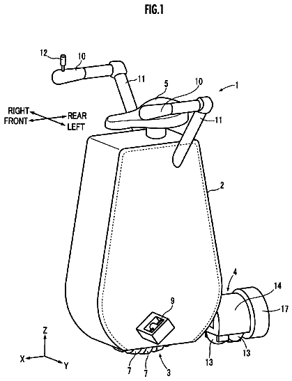
An electric vehicle wherein a seat post is provided as one of the components of a body frame for housing a battery.
US 8,678,127 B2 · Assignee: Yanmar Co., Ltd. · Inventors: Mitsuda; Masataka et al.
Sheet 1 of 24 from the published document. All sheets in the USPTO PDF
A work vehicle limited in a mounting space is adapted to have an engine, which is provided with an exhaust gas cleaning device, easily arranged therein. An engine device, which is to be mounted on the work vehicle, is provided with the engine mounted on a machine body and covered with a hood, an air cleaner for cleaning air introduced into the engine, and an exhaust gas cleaning device for cleaning exhaust gas from the engine. The exhaust gas cleaning device is arranged on a flywheel housing fitted on one side portion of the engine.
There has been known a technology in which a diesel particulate filter (or NOx catalyst) or the like is arranged as an exhaust gas cleaning device (after-treatment device) in an exhaust gas path of a diesel engine and in which exhaust gas exhausted from the diesel engine is cleaned by the diesel particulate filter (or NOx catalyst) or the like (see patent literature 1, patent literature 2, and patent literature 3). Further, there has been also known a technology in which a filter case (inner case) is fitted in a casing (outer case) and in which a particulate filter is arranged in the filter case (see patent literature 4).
1 of 24 drawing sheets so far from the published document, cropped to the drawing. Every sheet is in the USPTO PDF.
What the patent claimed, word for word. All of it is now free to use.
The present invention relates to an engine device used for a work vehicle such as a backhoe, a crane car, a fork lift, and a tractor and, more particularly, to an engine and an engine device of an exhaust gas cleaning device and the like which are arranged in a work vehicle.
There has been known a technology in which a diesel particulate filter (or NOx catalyst) or the like is arranged as an exhaust gas cleaning device (after-treatment device) in an exhaust gas path of a diesel engine and in which exhaust gas exhausted from the diesel engine is cleaned by the diesel particulate filter (or NOx catalyst) or the like (see patent literature 1, patent literature 2, and patent literature 3). Further, there has been also known a technology in which a filter case (inner case) is fitted in a casing (outer case) and in which a particulate filter is arranged in the filter case (see patent literature 4).
Patent document 1: Japanese Patent Application Laid-open No. 2000-145430 Patent document 2: Japanese Patent Application Laid-open No. 2003-27922 Patent document 3: Japanese Patent Application Laid-open No. 2008-82201 Patent document 4: Japanese Patent Application Laid-open No. 2001-173429
In this regard, a diesel engine has broad utility and is used in various fields such as an agricultural machine, a construction machine, and a ship. A mounting space in which the diesel engine is mounted is varied in size according to a vehicle mounted with the diesel engine. However, especially in a work vehicle such as a backhoe, a turning radius is required to be made as small as possible in order to prevent the work vehicle from coming into contact with its surroundings, so that a machine body itself needs to be made compact in size and is limited (narrow) in the mounting space in many cases.
On the other hand, in the above-mentioned exhaust gas cleaning device, the temperature of the exhaust gas passing through the exhaust gas cleaning device is desired to have a high temperature (for example, 300.degree. C. or more) from the viewpoint of function, so that there is made a request to provide the diesel engine with the exhaust gas cleaning device.
However, in order to apply a diesel engine provided with an exhaust gas cleaning device to a work vehicle (especially to a backhoe), not only the diesel engine provided with the exhaust gas cleaning device but also various kinds of parts such as an air cleaner, a radiator, and a battery need to be efficiently arranged in a narrow mounting space. Moreover, in addition to the problem that the mounting space is limited in size, there will be also presented a problem that engine vibrations caused when the engine is driven are easily transmitted directly to the exhaust gas cleaning device and a problem that when cooling air from a cooling fan provided in the diesel engine blows directly on the exhaust gas cleaning device, the temperature of the exhaust gas cleaning device, by extension, the temperature of the exhaust gas could be lowered.
Hence, the invention in the application is intended to improve a current situation like this.
To accomplish the object described above, the invention discloses a work vehicle-mounted engine device including: an engine mounted on a machine body and covered with a hood; an air cleaner for cleaning air introduced into the engine; an exhaust gas cleaning device for cleaning exhaust gas from an exhaust manifold of the engine, wherein a cooling fan is arranged on one side portion of the engine, and wherein a flywheel housing is fitted to an other side portion of the engine opposite to the one side portion where the cooling fan is arranged, a support body being fitted on an upper portion of the flywheel housing; and the exhaust gas cleaning device being fitted on the flywheel housing via the support body.
According to the invention, the exhaust gas cleaning device is arranged close to a cylinder head of the engine.
According to the invention, the air cleaner is arranged at a position lower than an upper surface of the engine and on one side of the engine; and that the exhaust gas cleaning device is arranged on an other side of the engine.
According to the invention, disclosed is a structure in which the engine and a counter weight to achieve a weight balance of a work vehicle are arranged on a turning machine body rotatable around a vertical axis and in which an exhaust gas pipe is made to communicate with the exhaust gas cleaning device; and in that an exhaust outlet side of the exhaust gas pipe is faced to a through hole formed in the counter weight.
According to the invention, disclosed is a structure in which the engine and a counter weight as a weight balancer of a work vehicle are arranged on a turning machine body rotatable around a vertical axis and in which an exhaust gas pipe is made to communicate with the exhaust gas cleaning device; and in that an exhaust port side of the exhaust gas pipe is passed through a through hole formed in the counter weight.
According to the invention, disclosed is a work vehicle structure in which a chassis for forming an engine room is fitted in the hood and in which an outer peripheral side of the engine is surrounded by the chassis for forming an engine room; and in that the air cleaner and the exhaust gas cleaning device are arranged in an engine room space surrounded by the chassis at positions separate from an upper surface of the engine.
According to the invention, disclosed is a battery for supplying electric power arranged below an engine cooling radiator and on a side of a radiator drain, the engine cooling radiator being arranged opposite to the cooling fan in the hood.
According to the invention, disclosed is a controller for controlling an operation of a turning work vehicle is arranged in the hood and above the cooling fan.
According to the invention, a cooling fan is arranged on one side portion of an engine in a hood, whereas an exhaust gas cleaning device for cleaning exhaust gas from the engine is arranged on a flywheel housing fitted to a side portion of the engine opposite to the cooling fan. That is, the exhaust gas cleaning device is arranged on the leeward side of the cooling fan across a main body of the engine. Hence, wind sent from the cooling fan and blowing directly on the exhaust gas cleaning device can be reduced, so that the temperature of the exhaust gas cleaning device can be prevented from being lowered by the wind sent from the cooling fan. Thus, the temperature of the exhaust gas can be easily kept more than a specified temperature. Moreover, the exhaust gas cleaning device can be coupled to the top of the flywheel housing of high rigidity, so that the exhaust gas cleaning device can be prevented from being damaged by vibrations or the like.
According to the invention, the exhaust gas cleaning device is arranged close to a cylinder head positioned at the upper portion of the engine. That is, the exhaust gas cleaning device is arranged on the leeward side of the cooling fan across the cylinder head. Hence, wind sent from the cooling fan and blowing directly on the exhaust gas cleaning device can be reduced by the cylinder head. Thus, the temperature of the exhaust gas can be easily kept more than a specified temperature. Moreover, the exhaust gas cleaning device can be coupled to the top of the flywheel housing of high rigidity, so that the exhaust gas cleaning device can be prevented from being damaged by vibrations or the like.
According to the invention, an air cleaner is arranged on the side of the exhaust gas cleaning device at a position lower than an upper end of the engine, so that the exhaust gas cleaning device and the air cleaner can be compactly arranged between the inner surface of the hood and the engine. The height of the upper surface of the hood with respect to the earth can be decreased as compared with a structure in which the exhaust gas cleaning device and the air cleaner are arranged on the upper surface side of the engine. Moreover, the upper surface side of the engine is arranged close to the hood and the exhaust gas cleaning device is arranged close to the air cleaner, so that the temperature of the exhaust gas cleaning device (exhaust gas in the exhaust gas cleaning device) can be kept by the exhaust heat from the engine and the exhaust gas cleaning device, and the air cleaner can be easily heated.
According to the invention, a counter weight is fitted on a side portion of a machine body and a through hole is formed in the counter weight and an exhaust outlet side of an exhaust gas pipe is faced to the through hole, so that an exhaust gas outlet side of the exhaust gas cleaning device can be made to communicate with the through hole at an extremely close range. This makes it possible to form the exhaust gas pipe in a short length and to improve the workability of a fitting work.
According to the invention, a counter weight is fitted on a side portion of the machine body and a through hole is formed in the counterweight and the exhaust outlet side of the exhaust gas pipe is passed through the through hole, so that the exhaust gas pipe can be extended on the outside of the hood at an extremely close range via the through hole. This makes it possible to form the exhaust gas pipe in a short length and to improve the workability of a fitting work.
According to the invention, a chassis for forming an engine room is fitted in the hood and an outer peripheral side of the engine is surrounded by the chassis for forming an engine room, and the air cleaner and the exhaust gas cleaning device are arranged separately from an upper surface of the engine. Hence, for example, the cylinder head, an exhaust manifold, and an intake manifold can have their upper surface sides exposed to the outside, which makes it possible to easily perform a maintenance work related to the engine. The air cleaner and the exhaust gas cleaning device can be easily protected by the chassis (such as a canopy fitting chassis and an engine support chassis) for forming an engine room.
According to the invention, a radiator for cooling an engine is arranged opposite to the cooling fan in the hood and a battery for supplying electric power is arranged below the radiator and on the side of a radiator drain, so that a space below the radiator can be effectively utilized as an arrangement space of the battery. The efficiency of utilizing an interior space of the hood can be enhanced.
According to the invention, disclosed is a controller for controlling the operation of a turning work vehicle and has the controller arranged above the cooling fan in the hood. Hence, the controller can be prevented from being heated by the exhaust heat from the exhaust gas cleaning device. The malfunction of the controller can be reduced. The durability of the controller can be improved.
FIG. 1 is a cross-sectional view, when viewed from the front, of an exhaust gas cleaning device of an embodiment.
FIG. 2 is an external bottom view of the same.
FIG. 3 is a left side view, when viewed from an exhaust gas inflow side, of the same.
FIG. 4 is a right side cross-sectional view, when viewed from an exhaust gas outflow side, of the same.
FIG. 5 is an exploded cross-sectional view, when viewed from the front, in FIG. 1.
FIG. 6 is an enlarged cross-sectional view, when viewed from the front, of an exhaust gas outflow side of the same.
FIG. 7 is an enlarged cross-sectional view, when viewed from the side, of an exhaust gas outflow side of the same.
FIG. 8 is an enlarged bottom view of an exhaust gas inflow side of the same.
FIG. 9 is an enlarged cross-sectional view, when viewed in a plan view, of an exhaust gas inflow side of the same.
FIG. 10 is an enlarged cross-sectional view, when viewed in a plan view, of an exhaust gas inflow side, which shows a modified example of FIG. 9.
FIG. 11 is an enlarged cross-sectional view, when viewed in a plan view, of an exhaust gas inflow side, which shows another modified example of FIG. 9.
FIG. 12 is an enlarged cross-sectional view, when viewed in a plan view, of an exhaust gas inflow side, which shows still another modified example of FIG. 9.
FIG. 13 is an enlarged cross-sectional view, when viewed in a plan view, of an exhaust gas inflow side, which shows still another modified example of FIG. 9.
FIG. 14 is an enlarged cross-sectional view, when viewed in a plan view, of an exhaust gas inflow side, which shows still another modified example of FIG. 9.
FIG. 15 is a left side view of a diesel engine.
FIG. 16 is a plan view of the diesel engine.
FIG. 17 is a front view of the diesel engine.
FIG. 18 is a rear view of the diesel engine.
FIG. 19 is a side view of a backhoe.
FIG. 20 is a plan view of the backhoe.
FIG. 21 is a plan view of a turning machine body.
FIG. 22 is a plan view to show an arrangement configuration on the turning machine body.
FIG. 23 is a front side view to show an arrangement configuration on the turning machine body.
FIG. 24 is a right side view to show an arrangement configuration on the turning machine body.
Hereinafter, an embodiment to embody the present invention will be described on the basis of the drawings. Here, in the following description, an exhaust gas inflow side is simply referred to as a left side and an exhaust gas outflow side is simply referred to as a right side.
First, the general structure of an exhaust gas cleaning device will be described with reference to FIG. 1 to FIG. 9. As shown in FIG. 1 to FIG. 5, the exhausted gas cleaning device of the present invention is provided with a continuous regeneration type diesel particulate filter 1 (hereinafter referred to as "DPF"). The DPF 1 is used to physically collect particulate matter (PM) or the like in exhaust gas. The DPF 1 has a structure in which a diesel oxidation catalyst 2 such as platinum for producing nitrogen dioxide (NO.sub.2) and a honeycomb structured soot filter 3 for continuously oxidizing and removing the collected particulate matter (PM) at a comparatively low temperature are arranged in series in a direction in which the exhaust gas moves (in a direction from a left side to a right side in FIG. 1). The DPF 1 is constructed in such a way that the soot filter 3 is continuously regenerated. The DPF 1 not only can remove the particulate matter (PM) in the exhaust gas but also can reduce carbon monoxide (CO) and hydrocarbon (HC) in the exhaust gas.
A structure for fitting the diesel oxidation catalyst 2 will be described with reference to FIG. 1 and FIG. 5. As shown in FIG. 1 and FIG. 5, the diesel oxidation catalyst 2 as a gas cleaning filter for cleaning exhaust gas exhausted from an engine is fitted in a catalyst inner case 4 that is made of a heat resistant metal material nearly in the shape of a cylinder. The catalyst inner case 4 is fitted in a catalyst outer case 5 that is made of a heat resistant metal material nearly in the shape of a cylinder. That is, the catalyst inner case 4 is fitted onto the outside of the diesel oxidation catalyst 2 via a catalyst heat insulation material 6 made of ceramic fiber in the shape of a mat. Moreover, the catalyst outer case 5 is fitted onto the outside of the catalyst inner case 4 via a support body 7 made of a thin plate and having an end face shaped like a letter I. Here, the diesel oxidation catalyst 2 is protected by the catalyst heat insulation material 6. The stress (deforming force) transmitted to the catalyst inner case 4 from the catalyst outer case 5 is reduced by the support body 7 made of the thin plate.
As shown in FIG. 1 and FIG. 5, a circular disk-shaped left cover body 8 is firmly fixed to the left end portions of the catalyst inner case 4 and the catalyst outer case 5 by welding. A sensor connection plug 10 is firmly fixed to the left cover body 8 via a sitting plate 9. The left end face 2a of the diesel oxidation catalyst 2 and the left cover body 8 are opposed to each other separately by a specified distance L1 for a gas inflow space. An exhaust gas inflow space 11 is formed between the left end face 2a of the diesel oxidation catalyst 2 and the left cover body 8. In this regard, the sensor connection plug 10 has an inlet side exhaust gas pressure sensor and an inlet side exhaust gas temperature sensor, both of which are not shown in the drawing, connected thereto.
As shown in FIG. 1, FIG. 5, and FIG. 9, an ellipsoidal exhaust gas inflow port 12 is opened in the left end portions of the catalyst inner case 4, which has the exhaust gas inflow space 11 formed therein, and the catalyst outer case 5. The ellipsoidal exhaust gas inflow port 12 has a short diameter formed in a direction in which the exhaust gas moves (in the direction of a center line of the cases 4, 5) and has a long diameter formed in a direction perpendicular to the direction in which the exhaust gas moves (in the circumferential direction of the cases 4, 5). A closing ring body 15 is clamped and fixed between an opening edge 13 of the catalyst inner case 4 and an opening edge 14 of the catalyst outer case 5. A clearance between the opening edge 13 of the catalyst inner case 4 and the opening edge 14 of the catalyst outer case 5 is closed by the closing ring body 15. The closing ring body 15 prevents the exhaust gas from flowing into a clearance between the catalyst inner case 4 and the catalyst outer case 5.
As shown in FIG. 1, FIG. 3, FIG. 5, and FIG. 8, an exhaust gas inlet pipe 16 is arranged on the outside surface of the catalyst outer case 5 having the exhaust gas inflow port 12 formed therein. An open end portion 16a formed in the shape of a true circle on the small diameter side of the exhaust gas inlet pipe 16 has an exhaust connection flange body 17 welded thereto. The exhaust connection flange body 17 is fastened to an exhaust manifold 71 of a diesel engine 70, which will be described later, with a bolt 18. An open end portion 16b formed in the shape of a true circle on the large diameter side of the exhaust gas inlet pipe 16 is welded to the outside surface of the catalyst outer case 5. The exhaust gas inlet pipe 16 is formed in a shape expanding toward an end (in the shape of a bugle) from the open end portion 16a formed in the shape of a true circle on the small diameter side to the open end portion 16b formed in the shape of a true circle on the large diameter side.
As shown in FIG. 1, FIG. 5, and FIG. 8, of the outside surface of the catalyst outer case 5, the outside surface of the left end portion of the opening edge 14 of the catalyst outer case 5 is welded to the left end portion of the open end portion 16b formed in the shape of a true circle on the large diameter side of the exhaust gas inlet pipe 16. That is, the exhaust gas inlet pipe 16 (open end portion 16b formed in the shape of the true circle on the large diameter side) is arranged offset on the downstream side in which the exhaust gas moves (on the right side of the catalyst outer case 5) with respect to the exhausted gas inflow part 12. That is, the ellipsoidal exhaust gas inflow port 12 is formed in the catalyst outer case 5 in such a way as to be arranged offset on the upstream side in which the exhaust gas moves (to the left side of the catalyst outer case 5) with respect to the exhaust gas inlet pipe 16 (open end portion 16b formed in the shape of the true circle on the large diameter side).
According to the above-mentioned construction, the exhaust gas from the engine 70 flows into the exhaust gas inlet pipe 16 from the exhaust manifold 71 and flows into the exhaust gas inflow space 11 through the exhaust gas inflow port 12 from the exhaust gas inlet pipe 16 and is supplied to the diesel oxidation catalyst 2 from the left end face 2a. Nitrogen dioxide (NO.sub.2) is produced by the oxidation action of the diesel oxidation catalyst 2. Moreover, a support leg body 19 is welded to the outer peripheral surface of the catalyst outer case 5. When the DPF 1 is fitted to the engine 70, the catalyst outer case 5 is fixed to a flywheel housing 78 or the like of the diesel engine 70 via the support leg body 19, which will be described later in detail.
A structure of fitting the soot filter 3 will be described with reference to FIG. 1 and FIG. 5. As shown in FIG. 1 and FIG. 5, the soot filter 3 acting as a gas cleaning filter for cleaning the exhaust gas exhausted from the engine 70 is fitted in a filter inner case 20 made of a heat resistant metal material nearly in the shape of a cylinder. The filter inner case 20 is fitted in a filter outer case 21 made of a heat resistant metal material nearly in the shape of a cylinder. That is, the filter inner case 20 is fitted onto the outside of the soot filter 3 via a filter heat insulation material 22 made of ceramic fiber in the shape of a mat. In this regard, the soot filter 3 is protected by the filter heat insulation material 22.
As shown in FIG. 1 and FIG. 5, a catalyst-side flange 25 is welded to an end portion on the downstream side (right side), in which the exhaust gas moves, of the catalyst outer case 5. A filter-side flange 26 is welded to a middle portion in the direction in which the exhaust gas moves of the filter inner case 20 and to an end portion on the upstream side (left side), in which the exhaust gas moves, of the filter outer case 21. The catalyst-side flange 25 is detachably fastened to the filter-side flange 26 by bolts 27 and nuts 28. In this regard, the diameter of the cylindrical catalyst inner case 4 is nearly equal to the diameter of the cylindrical filter inner case 20. Further, the diameter of the cylindrical catalyst outer case 5 is nearly equal to the diameter of the cylindrical filter outer case 21.
As shown in FIG. 1, in the state in which the filter outer case 21 is coupled to the catalyst outer case 5 via the catalyst-side flange 25 and the filter-side flange 26, the end portion on the upstream side (left side), in which the exhaust gas moves, of the filter inner case 20 is opposed to the end portion on the downstream side (right side), in which the exhaust gas moves, of the catalyst inner case 4 in such a way as to be separated from each other by a specified gap L2 in which sensors are to be fitted. That is, a sensor fitting space 29 is formed between the end portion on the downstream side (right side), in which the exhaust gas moves, of the catalyst inner case 4 and the end portion on the upstream side (left side), in which the exhaust gas moves, of the filter inner case 20. Sensor connection plugs 50 are fixed to the catalyst outer case 5 positioned in the sensor fitting space 29. The sensor connection plugs 50 have a filter inlet-side exhaust gas pressure sensor and a filter inlet-side exhaust gas temperature sensor (thermistor), both of which are not shown in the drawing, connected thereto.
As shown in FIG. 5, a cylinder length L4 in the direction in which the exhaust gas moves of the catalyst outer case 5 is made longer than a cylinder length L3 in the direction in which the exhaust gas moves of the catalyst inner case 4. A cylinder length L6 in the direction in which the exhaust gas moves of the filter outer case 21 is made shorter than a cylinder length L5 in the direction in which the exhaust gas moves of the filter inner case 20. The sum of the lengths (L2+L3+L5) of the specified gap L2 of the sensor fitting space 29, the cylinder length L3 of the catalyst inner case 4, and the cylinder length L5 of the filter inner case 20 is made nearly equal to the sum of the lengths (L4+L6) of the cylinder length L4 of the catalyst outer case 5 and the cylinder length L6 of the filter outer case 21. The end portion on the upstream side (left side), in which the exhaust gas moves, of the filter inner case 20 is protruded from the end portion on the upstream side (left side), in which the exhaust gas moves, of the filter outer case 21 by a difference between their lengths (L7=L5-L6). That is, when the filter outer case 21 is coupled to the catalyst outer case 5, the end portion on the upstream side (left side), in which the exhaust gas moves, of the filter inner case 20 is inserted into the downstream side (right side), in which the exhaust gas moves, of the catalyst outer case 5 by an overlap length L7.
According to the above mentioned construction, the nitrogen dioxide (NO.sub.2) produced by the oxidation action of the diesel oxidation catalyst 2 is supplied to the soot filter 3 from the left end face 3a of the soot filter 3. The collected particulate matter (PM) in the exhaust gas from the diesel engine 70 collected by the soot filter 3 is continuously oxidized and removed by nitrogen dioxide (NO.sub.2) at a comparatively low temperature. Not only the particulate matter (PM) in the exhaust gas from the engine 70 collected by the soot filter 3 is removed, but also carbon monoxide (CO) and hydrocarbon (HC) in the exhaust gas from the engine 70 is reduced.
As shown in FIG. 1 to FIG. 5, in the exhaust gas cleaning device including the diesel oxidation catalyst 2 and the soot filter 3 as the gas cleaning filter for cleaning the exhaust gas exhausted from the diesel engine 70, the catalyst inner case 4 and the filter inner case 20 which have the diesel oxidation catalyst 2 and the soot filter 3 fitted therein respectively, and the catalyst outer case 5 and the filter outer case 21 which have the catalyst inner case 4 and the filter inner case 20 fitted therein respectively, the present embodiment is provided with a plurality of sets of diesel oxidation catalyst 2 and soot filter 3, catalyst inner case 4 and filter inner case 20, and catalyst outer case 5 and filter outer case 21 and is constructed in such a way that a catalyst-side flange 25 and a filter-side flange 26, both of which act as flange bodies for coupling the catalyst outer case 5 and the filter outer case 21, are arranged offset with respect to a connection boundary position of the diesel oxidation catalyst 2 and the soot filter 3. Hence, when a spacing between a junction portion of the diesel oxidation catalyst 2 and a junction portion of the soot filter 3 is shortened, the coupling length of the catalyst outer case 5 and the filter outer case 21 can be shortened. Moreover, a gas sensor and the like can be easily arranged at the connection boundary position of the diesel oxidation catalyst 2 and the soot filter 3. The lengths in the direction in which the exhaust gas moves of the catalyst outer case 5 and the filter outer case 21 can be shortened, so that the catalyst outer case 5 and the filter outer case 21 and the like can be increased in rigidity and decreased in weight.
As shown in FIG. 1 to FIG. 5, the present embodiment is structured by two kinds of diesel oxidation catalyst 2 and soot filter 3 and is constructed in such a way that the filter inner case 20 having one the one soot filter 3 fitted therein is overlapped by the catalyst outer case 5 having the catalyst inner case 4 of the other diesel oxidation catalyst 2, so that while the length in the direction in which the exhaust gas moves of the diesel oxidation catalyst 2 and the soot filter 3 is ensured, the length in the direction in which the exhaust gas moves of the catalyst outer case 5 and the filter outer case 21 can be shortened. Further, when the catalyst outer case 5 and the filter outer case 21 are separated (disassembled) from each other, the catalyst inner case 4 (the other diesel oxidation catalyst 2) overlapped by the catalyst outer case 5 is greatly exposed to the outside, so that the exposed range in which the catalyst inner case 4 (the other diesel oxidation catalyst 2) is enlarged, which makes it possible to easily perform a maintenance work of removing soot on the one soot filter 3 and the other maintenance works.
As shown in FIG. 1 to FIG. 5, the present embodiment is provided with the diesel oxidation catalyst 2 and the soot filter 3 as a plurality of gas cleaning filters and is constructed in such a way that the catalyst-side flange 25 and the filter-side flange 26 are arranged offset on the outer peripheral side of the soot filter 3. Hence, when the catalyst outer case 5 and the filter outer case 21 are separated from each other, the end portion of the filter inner case 20 on the exhaust gas inlet side of the soot filter 3 can be greatly exposed from the end face of the filter outer case 21, which makes it possible to easily perform the maintenance work of removing soot deposited on the soot filter 3 and the filter inner case 20.
As shown in FIG. 1 to FIG. 5, the present embodiment is structured by two kinds of diesel oxidation catalyst 2 and soot filter 3 and has the sensor fitting space 29 formed between the catalyst inner case 4 having the one diesel oxidation catalyst 2 fitted therein and the filter inner case 20 having the other soot filter 3 fitted therein. Hence, while the coupling length in the direction in which the exhaust gas moves of the catalyst outer case 5 and the filter outer case 21 is shortened to increase the rigidity of the catalyst outer case 5 and the filter outer case 21 and the like and to decrease the weight of the same, the gas sensor or the like can be arranged in the sensor fitting space 29 at the connection boundary position of the diesel oxidation catalyst 2 and the soot filter 3.
As shown in FIG. 1 to FIG. 5, the present embodiment is constructed in such a way that the sensor connection plugs 50 as the sensor support bodies are fitted on the catalyst outer case 5 overlapping the filter inner case 20 and that gas sensors such as a filter inlet-side exhaust gas pressure sensor and a filter inlet-side exhaust gas temperature sensor (thermistor), both of which are not shown in the drawing, are arranged at the connection boundary position of the diesel oxidation catalyst 2 and the soot filter 3 via the sensor connection plugs 50. Hence, while the catalyst outer case 5 and the filter outer case 21 and the like are increased in rigidity and decreased in weight, the sensor connection plugs 50 can be arranged at the connection boundary position of the diesel oxidation catalyst 2 and the soot filter 3.
As shown in FIG. 1 to FIG. 5 and FIG. 8, in the exhaust gas cleaning device provided with the diesel oxidation catalyst 2 or the soot filter 3 as the gas cleaning filter for cleaning the exhaust gas exhausted from the diesel engine 70, the catalyst inner case 4 or the filter inner case 20 as the inner case having the diesel oxidation catalyst 2 or the soot filter 3 fitted therein, and the catalyst outer case 5 or the filter outer case 21 as the outer case having the catalyst inner case 4 or the filter inner case 20 fitted therein, the exhaust gas inflow port 12 is formed in the peripheral surfaces on the one end sides of the catalyst inner case 4 and the catalyst outer case 5 and the exhaust gas inlet pipe 16 is arranged outside the exhaust gas inflow port 12 of the outer periphery of the catalyst outer case 5 and the area of the opening end face on the exhaust gas outlet side of the exhaust gas inlet pipe 16 is made larger than the area of the opening end face on the exhaust gas inlet side of the exhaust gas inlet pipe 16.
Hence, the exhaust gas inlet pipe can be arranged closer to a portion in which the diesel oxidation catalyst 2 is fitted, so that the length in the direction in which the exhaust gas moves of the catalyst outer case 5 (casing) on the upstream side of the exhaust gas from the diesel oxidation catalyst 2 can be easily shortened. That is, the end face of the diesel oxidation catalyst 2 can be easily arranged closer to the end face on the upstream side in the direction in which the exhaust gas moves of the catalyst outer case 5. Moreover, by making the area of the opening end face on the exhaust gas outlet side of the exhaust gas inlet pipe 16 larger than the area of the opening end face on the exhaust gas inlet side of the exhaust gas inlet pipe 16, the exhaust gas inlet pipe 16 can be welded to the outer peripheral surface of the catalyst outer case 5. Hence, without providing a reinforcing member, which is used in the related art, for coupling the catalyst outer case 5 to the exhaust gas inlet side pipe 16, the fitting strength of the exhaust gas inlet pipe 16 on the exhaust gas inlet side of the catalyst outer case 5 can be held and the exhaust pressure loss of the exhaust gas at the catalyst outer case 5 and the exhaust gas inlet pipe 16 can be decreased.
As shown in FIG. 1, FIG. 2, FIG. 5, and FIG. 8, the present embodiment is constructed in such a way that the end edge on the exhaust gas outlet side of the exhaust gas inlet pipe 16 is fixed to the outer peripheral surface of the exhaust gas inlet of the catalyst outer case 5 and that the exhaust gas inlet pipe 16 is arranged offset on the downstream side of the exhaust gas from the catalyst outer case 5 with respect to the exhaust gas inlet port 12 of the catalyst outer case 5. Hence, the end face on the upstream side of the exhaust gas from the diesel oxidation catalyst 2 can be arranged closer to the upstream side of the exhaust gas than the opening edge on the exhaust gas downstream side of the exhaust gas from the exhaust gas inlet pipe 16, so that of the length in the direction in which the exhaust gas moves of the catalyst outer case 5, the length on the upstream side of the exhaust gas can be easily shortened. That is, the catalyst outer case 5 can be made compact in the length in the direction in which the exhaust gas moves. That is, the exhaust gas outlet side of the exhaust gas inlet pipe 16 can be arranged separately from the side end face on the upstream side in the direction in which the exhaust gas moves of the catalyst outer case 5. The present embodiment can be shortened in the dimension in the direction in which the exhaust gas moves of the catalyst outer case 5, so that the present embodiment can be constructed of a smaller number of parts, at lower cost, more compactly, and in lighter weight than ever.
As shown in FIG. 1, FIG. 2, FIG. 5, and FIG. 8, in the direction in which the exhaust gas moves of the catalyst outer case 5, the opening on the exhaust gas outlet side of the exhaust gas inlet pipe 16 is made larger in size than the opening of the exhaust gas inflow port 12 of the catalyst outer case 5 and the catalyst inner case 4. Hence, without a reinforcing member used in the related art, the fitting strength of the exhaust gas inlet pipe 16 on the exhaust gas inlet side of the catalyst outer case 5 can be held and the exhaust pressure loss of the exhaust gas inlet pipe 16 and the exhaust gas inflow port 12 of the catalyst outer case 5 can be decreased. As compared with a structure having a reinforcing member in the related art, the present embodiment can be constructed of a smaller number of constituent parts at lower cost. The catalyst outer case 5 can be made compact in the outer shape and can be easily decreased in the weight, whereas the exhaust gas inlet side of the catalyst outer case 5 and the exhaust gas inlet pipe 16 can be made highly rigid. That is, the exhaust gas inlet of the catalyst outer case 5 and the catalyst inner case 4 can be formed close to the side end face on the upstream side in the direction in which the exhaust gas moves of the catalyst outer case 5. The present embodiment can be shortened in the dimension in the direction in which the exhaust gas moves of the catalyst outer case 5, so that the present embodiment can be constructed of a smaller number of parts, at lower cost, more compactly, in lighter weight than ever.
As shown in FIG. 1, FIG. 2, FIG. 5, and FIG. 8, the present embodiment is constructed in such a way that the end face on the upstream side in the direction in which the exhaust gas moves of the diesel oxidation catalyst 2 or the soot filter 3 is arranged closer to the upstream side in the direction in which the exhaust gas move of the catalyst outer case 5 than the end portion on the downstream side in the direction in which the exhaust gas moves on the exhaust gas outlet side of the exhaust gas inlet pipe 16. Hence, of the length in the direction in which the exhaust gas moves of the catalyst outer case 5, the length on the upstream side of the exhaust gas can be easily shortened, and hence the catalyst outer case 5 can be made compact in the length in the direction in which the exhaust gas moves.
As shown in FIG. 1, FIG. 2, FIG. 5, and FIG. 8, the present embodiment is constructed in such a way that of the opening edge of the exhaust gas inflow port 12 of the catalyst outer case 5, the end portion on the exhaust gas outlet side of the exhaust gas inlet pipe 16 is coupled to the opening edge of the exhaust gas inflow port 12 on the upstream side in the direction in which the exhaust gas moves. Hence, of the length in the direction in which the exhaust gas moves of the catalyst outer case 5, the length on the upstream side of the exhaust gas can be easily shortened, whereas the exhaust pressure loss of the exhaust gas in the catalyst outer case 5 and the exhaust gas inlet pipe 16 can be reduced.
In this regard, as described above, the present embodiment is provided with the diesel oxidation catalyst 2 and the soot filter 3 as the gas cleaning filter for cleaning exhaust gas exhausted from the engine. However, in place of the diesel oxidation catalyst 2 and the soot filter 3, the present embodiment may be provided with a NOx selectively reducing catalyst (NOx removing catalyst) for reducing nitrogen oxide (NOx) in the exhaust gas from the engine 70 by ammonia (NH.sub.3) produced by adding urea (reducing agent) and an ammonia removing catalyst for removing remaining ammonia emitted from the NOx selectively reducing catalyst.
As described above, when the catalyst inner case 4 is provided with the NOx selectively reducing catalyst (NOx removing catalyst) as the gas cleaning filter and the filter inner case 20 is provided with the ammonia removing catalyst, nitrogen oxide (NOx) in the exhaust gas exhausted from the engine 70 can be reduced and emitted as harmless nitrogen gas (N.sub.2).
As shown in FIG. 1 to FIG. 5, in the exhaust gas cleaning device provided with the diesel oxidation catalyst 2 and the soot filter 3 as the gas cleaning filter for cleaning the exhaust gas exhausted from the diesel engine 70, the catalyst inner case 4 and the filter inner case 20 having the diesel oxidation catalyst 2 and the soot filter 3 fitted therein respectively, and the catalyst outer case 5 and the filter outer case 21 having the catalyst inner case 4 and the filter inner case 20 fitted therein respectively, the catalyst inner case 4 and the filter inner case 20 are coupled to the catalyst outer case 5 and the filter outer case 21, respectively, and the exhaust gas inlet pipe 16 as an inlet constituent part having an external force applied thereto and the support leg body 19 as the support body are arranged on the catalyst outer case 5.
Hence, the external stress can be supported by the catalyst outer case 5 and hence the external stress applied to the catalyst inner case 4 and the filter inner case 20 as a deforming force can be reduced. The double structure of the catalyst inner case 4 and the filter inner case 20 and the catalyst outer case 5 and the filter outer case 21 not only can enhance the heat insulation of the diesel oxidation catalyst 2 and the soot filter 3 and the processing capacity and the regeneration capacity of the diesel oxidation catalyst 2 and the soot filter 3, but also can easily prevent the diesel oxidation catalyst 2 and the soot filter 3 from being improperly supported, for example, by the transmission of vibrations from the engine 70 and the strain caused by welding.
The description continues in the full USPTO document.
About 7,312 words. The USPTO PDF has it with every drawing.
Fees are due 3.5, 7.5 and 11.5 years after grant. This patent expired on March 25, 2026, so the fee marked "not paid" was the one that went unpaid.
WORK VEHICLE-MOUNTED ENGINE DEVICE
Filed Sep 2009 · published Aug 2011Work vehicle-mounted engine device
Filed Sep 2009 · granted Mar 2014Earlier publications, parents and continuations. None of them can still be enforced, or this patent would not be listed.
Prior art cited by the examiner or applicant. Useful when you check your own idea for novelty.
Everything on this page comes from the documents linked above.