Background
As used herein, terms such as "user equipment" ("UE"), "mobile station" ("MS"), "user agent" ("UA"), "user device," and "user node" might in some cases refer to mobile devices such as mobile telephones, personal digital assistants, handheld or laptop computers, and similar devices that have telecommunications capabilities. Such terms can also refer to any hardware or software component (alone or in combination) that can terminate a communication session for a user. Such a component might also include one or more associated removable memory modules, such as but not limited to a Universal Integrated Circuit Card (UICC) that includes a Subscriber Identity Module (SIM) application, a Universal Subscriber Identity Module (USIM) application, or a Removable User Identity Module (R-UIM) application. Alternatively, such a component might consist of a device itself without such a module. In other cases, terms such as "UE" and the like might refer to devices that have similar capabilities but that are not transportable, such as desktop computers, set-top boxes, or network appliances.
As telecommunications technology has evolved, more advanced network access equipment has been introduced that can provide services that were not previously possible. This network access equipment might include systems and devices that are improvements of the equivalent equipment in a traditional wireless telecommunications system. Specifications regarding such advanced or next generation equipment may be included in evolving wireless communications standards, such as Long-Term Evolution (LTE) and LTE-Advanced (LTE-A). For example, an LTE or LTE-A system might be an Evolved Universal Terrestrial Radio Access Network (E-UTRAN) and include an Evolved Node B (or eNB), a wireless access point, a relay node, or a similar component rather than a traditional base station. As used herein, the term "eNB" may refer to "eNBs" but may also include any of these systems. These components may also be referred to as an access node. The terms "eNB" and "access node" may be synonymous in some embodiments.
Brief description of the drawings
Reference is now made to the following description, taken in connection with the accompanying drawings, wherein like reference numerals may represent like parts.
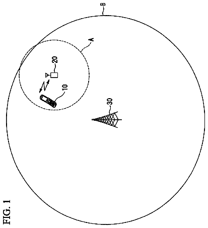
FIG. 1 is a schematic diagram of a radio access network that allows a UE to communicate with other network components and/or devices, according to an embodiment of the present disclosure.
FIG. 2 is an example of the definition for prach-ConfigIndex in 3GPP TS 36.211 V9.2.0, according to an embodiment of the present disclosure.
FIG. 3 is a flow diagram illustrating handover of a UE to E-UTRA, according to an embodiment of the present disclosure.
FIG. 4 illustrates a random access procedure for handover to E-UTRA by decoding the E-UTRA PBCH in order to determine the two least significant bits of the E-UTRA System Frame Number, according to an embodiment of the present disclosure.
FIG. 5 is a flowchart illustrating a UE's procedure to determine the E-UTRA radio frame to perform random access, synchronization indicators, and polarity determination for PRACH during inter-RAT handover, according to an embodiment of the present disclosure.
FIG. 6 is a flowchart illustrating an exemplary UE procedure during inter-RAT handover to determine the E-UTRA radio frame to perform random access, including a timing offset indication for the PRACH configuration, according to an embodiment of the present disclosure.
FIG. 7 illustrates a processor and related components suitable for implementing the several embodiments of the present disclosure.
Detailed description
It should be understood at the outset that although illustrative implementations of one or more embodiments of the present disclosure are provided below, the disclosed systems and/or methods may be implemented using any number of techniques. The disclosure should in no way be limited to the illustrative implementations, drawings, and techniques illustrated below, including the exemplary designs and implementations illustrated and described herein, but may be modified within the scope of the appended claims along with their full scope of equivalents.
As used throughout the specification, claims, and Figures, the following acronyms have the following definitions. Unless stated otherwise, all terms are defined by and follow the standards set forth by the Third Generation Partnership Program (3GPP) technical specifications or by the OMA (Open Mobile Alliance).
"CDMA" is defined as "Code Division Multiple Access."
"CR" is defined as "Change Request."
"DL" is defined as "DownLink."
"EDGE" is defined as "Enhanced Data rates for GSM Evolution."
"E-UTRA" is defined as "Evolved Universal Terrestrial Radio Access."
"FDD" is defined as "Frequency Division Duplexing."
"GERAN" is defined as "GSM EDGE Radio Access Network."
"GSM" is defined as "Global System for Mobile communications."
"HO" is defined as "Handover."
"HRPD" is defined as "High Rate Packet Data."
"IE" is defined as "Information Element."
"LSB" is defined as "Least Significant Bit."
"LTE" is defined as "Long Term Evolution."
"MIB" is defined as "Master Information Block."
"PBCH" is defined as "Physical Broadcast Channel."
"PRACH" is defined as "Physical Random Access Channel."
"PSS" is defined as "Primary Synchronization Signal."
"RA" is defined as "Random Access."
"RACH" is defined as "Random Access Channel."
"RAN" is defined as "Radio Access Network."
"RAT" is defined as "Radio Access Technology."
"RRC" is defined as "Radio Resource Control."
"SFN" is defined as "System Frame Number."
"SSS" is defined as "Secondary Synchronization Signal."
"TDD" is defined as "Time Division Duplexing."
"TDMA" is defined as "Time Division Multiple Access."
"UL" is defined as "UpLink."
"UTRA" is defined as "Universal Terrestrial Radio Access."
The term "may," as used herein, can contemplate embodiments in which an object or technique is either required, or possible but not required. Thus, for example, while the term "may" might be used, in some embodiments the term "may" could be replaced by the term "shall" or "must."
In one embodiment, the term "frame polarity" is defined as whether the radio frame has an even or odd SFN (that is, the radio frame has a mod 2 alignment). However, the embodiments specifically contemplate different alignments. For example, the embodiments described herein apply equally well to radio frames with other alignments, such as mod 4, mod 8, or any other radio frame alignment. Thus, as used herein, the term "polarity" is defined as including both mod 2 radio frame alignment and other radio frame alignments, including but not limited to mod 4 and mod 8.
The embodiments described herein relate to mechanisms to reduce the latency for a "Handover-to-E-UTRA" procedure, i.e., handover from a source cell with another RAT to a target E-UTRA cell. In addition, mechanisms are described to reduce the latency for intra-E-UTRA handover, i.e., the source and target cells are both E-UTRA cells, when the source and target cells are not synchronized.
In particular, signaling may be provided to allow a UE to determine whether the source and target cells of the handover are synchronized, and/or to determine a relative polarity of SFNs in the source and target cells. In an embodiment, both determinations may be made based on information received in a single indicator received from the source cell. Still further, if the source and target cells (in a synchronized or unsynchronized system) can determine the timing offset relative to one another, then parameters derived from the offset can be signaled to the UE so that the UE can determine the target cell frame polarity from the current time value of the source cell.
Stated differently, the embodiments relate to inter-RAT handover of a UE to an E-UTRAN. If the E-UTRAN PRACH configuration is not the same in all subframes, it may be beneficial for the UE to obtain the MIB from the E-UTRAN cell before the UE can perform a random access procedure. Obtaining the MIB may add latency to the handover thereby increasing the interruption time. This latency may occur even if the two networks involved in the handover are synchronized, because there is no mechanism to inform the UE that the networks are synchronized or to convey information about the timing relationship between the networks. Thus, the embodiments provide mechanisms to signal to the UE whether or not the networks are synchronized. These mechanisms also convey to the UE sufficient timing information so that the UE can perform a random access procedure in the E-UTRAN without obtaining the MIB. Multiple embodiments are described below.
FIG. 1 is a schematic diagram of a radio access network that allows a UE to communicate with other network components and/or devices according to an embodiment of the disclosure. In particular, FIG. 1 illustrates an embodiment of a RAN 100 that allows a UE to communicate with other network components and/or devices. The RAN 100 may be an LTE or LTE-A system, e.g., as described in 3GPP. For example, an LTE or LTE-A system might include an Evolved Universal Terrestrial Radio Access Network (E-UTRAN) Evolved Node B (or eNB), a wireless access point, or a similar component. FIG. 1 is exemplary and may have other components or arrangements in other embodiments. In an embodiment, the RAN 100 may comprise at least one access device 110 and at least one UE 120, which may be both located within a cell 130. The RAN 100 may also comprise or may be coupled to a network 140.
As described above, the term "access device" refers to any component of the wireless network, such as a traditional base station, a wireless access point, or an LTE or LTE-A Evolved Node B or eNB, that creates a geographical area of reception and transmission coverage allowing a UE 120 or a relay node (not shown) to access or communicate with other components in a telecommunications system, such as a second UE 120. In this document, the terms "access node" and "access device" may be used interchangeably. An access node may include various combinations of hardware and/or software.
The access device 110 may communicate with any UE 120 within the same cell 130, via a direct link, such as in a UTRAN. The cell 130 may be a geographical area of reception and transmission coverage. For instance, the direct link may be a point-to-point link established between the access device 110 and the UE 120 and used to transmit and receive signals between the two. Alternatively, the access devices 110 may communicate with any UE 120 in the same cell 130 over shared links, such as in an E-UTRAN. For instance, the shared links may comprise an uplink shared channel and a downlink shared channel. Additionally, the access device 110 may communicate with other components or devices in order to access a network 140 that might use network protocols or technologies similar to or different from those used by the RAN 100. In an embodiment, the UEs 120 may move about between different cells 130 and their communications may be handed over between the different cells 130, where the UEs 120 may communicate with different access devices 110.
The network 140 may be a wireless network, a wired network, or a combination of any wired or wireless networks. The networks may include a Wireless LAN (WLAN) network, an Ethernet based network, an Internet Protocol (IP) based network, a Digital Subscriber Line (DSL) network, an Optical communications network, and/or any other wireless or wired networks that may be used to exchange communications/data with the UE 120. The communications/data may comprise voice and/or video calls, emails, text/media messages (e.g. using Short Message Service (SMS) or Multimedia Messaging Service (MMS)), IP data, and/or any other data.
General Description of E-UTRA PRACH Configuration
In E-UTRA system, the eNB configures PRACH configuration for a UE through a PRACH-Config Information Element. The PRACH-Config Information Element may be defined in 3GPP TS 36.331 V9.3.0 as the following:
TABLE-US-00001 -- ASN1START PRACH-ConfigSIB ::= SEQUENCE { rootSequenceIndex INTEGER (0..837), prach-ConfigInfo PRACH-ConfigInfo } PRACH-Config ::= SEQUENCE { rootSequenceIndex INTEGER (0..837), prach-ConfigInfo PRACH-ConfigInfo OPTIONAL - - Need ON } PRACH-ConfigInfo ::= SEQUENCE { prach-ConfigIndex INTEGER (0..63), highSpeedFlag BOOLEAN, zeroCorrelationZoneConfig INTEGER (0..15), prach-FreqOffset INTEGER (0..94) }
Within the above PRACH-Config Information Element, prach-ConfigIndex is used to define the preamble format, the radio frames, and the subframe numbers that may be used to transmit preambles. FIG. 2 is an example of the definition for prach-ConfigIndex in 3GPP TS 36.211 V9.2.0. In this example, PRACH resources may be configured either on every radio frame or only on the even-numbered radio frames. If the E-UTRA cell configures PRACH to be transmitted only on radio frames with even SFNs, then it may be desirable for the UE to know whether the current SFN is even or odd before it can transmit on PRACH to access the system.
Similarly, if the E-UTRA cell configures the PRACH to be transmitted only on odd SFNs (which may be the case for a TDD system), then it may also be desirable for the UE to know whether the current SFN is even or odd before the UE can transmit on the PRACH to access the system.
Inter-RAT HO to E-UTRA
FIG. 3 is a flow diagram illustrating handover of a UE 300 to an E-UTRAN 302 from a network having a RAT other than E-UTRA, according to an embodiment of the present disclosure. The procedure shown in FIG. 3 may be implemented by a processor using instructions stored on a medium, such as the processor and media shown in FIG. 7.
In an embodiment, the E-UTRAN 302 may transmit an RRCConnectionReconfiguration message 304 to the UE 300, possibly via another RAN. In turn, the UE transmits an RRCConnectionReconfigurationComplete message 306 to the E-UTRAN. The process terminates thereafter.
The handover to E-UTRAN procedure shown in FIG. 3 may be used when the network hands over the UE from another RAT to E-UTRA. As described in 3GPP TS 36.331 V9.3.0, the RAN using another RAT initiates the handover-to-E-UTRA procedure, in accordance with the specifications applicable for the other RAT. This initiation may be performed by sending the RRCConnectionReconfiguration message via the RAT from which the inter-RAT handover is performed. FIG. 3 shows the signaling flow for the handover-to-E-UTRA procedure.
However, in the case where the target E-UTRA cell configures PRACH to be transmitted only on radio frames with even SFNs or only on radio frames with odd SFNs, it may be desirable for the UE to know whether the current SFN is even or odd before it can access the target E-UTRA cell after handover. Otherwise, the UE might not be able to access the target E-UTRA cell or might only be able to access the target E-UTRA cell after an additional delay. The embodiments described herein relate to addressing these and other issues.
Based on current E-UTRA specifications, when PRACH resources are not provisioned in every radio frame, the UE may assume the source and target radio frames are synchronized at the SFN level within the E-UTRAN. SFN synchronization implies that radio frames from the source and target cells are aligned within less than half a radio frame length, as observed at the UE. Thus, the UE might not have to wait to attempt decoding the PBCH to determine the polarity of the SFN before transmitting on PRACH. However, current specifications do not address the case for inter-RAT handovers.
FIG. 4 illustrates a random access procedure for handover to E-UTRA by decoding the E-UTRA PBCH in order to determine the two least significant bits of the E-UTRA System Frame Number, according to an embodiment of the present disclosure. The procedure shown in FIG. 4 may be implemented by a processor using instructions stored on a medium, such as the processor and media shown in FIG. 7.
The handover procedure to an E-UTRAN begins at block 400. The UE obtains the PSS and SSS (block 402). The UE then determines if the PRACH configuration is the same in all radio frames (block 404). If the determination in block 404 is "yes," then the UE performs the random access (block 406). The process terminates thereafter. If the determination to block 404 is "no," then the UE obtains the MIB by decoding the PBCH (block 408). The UE then performs the random access in an appropriate frame (block 410). The process terminates thereafter.
This procedure allows a UE to determine the frame polarity (even or odd) of the target E-UTRA system and transmit on PRACH. However, the PBCH TTI is a 40 ms interval, which leads to increased handover latency and interruption time. The embodiments described herein address and decrease this handover latency.
In an embodiment, a system may exhibit one or more the following properties: (a) the random access opportunities are not the same in all radio frames, (b) zero or more cells are synchronized and zero or more are unsynchronized, (c) reading the SFN of the target cell takes longer than gaining timing synchronization to the target cell, and (d) there is a desire to minimize HO latency and interruption time. In such a system, a signaling mechanism
may be needed or desired to inform the UE whether a handover is (un)synchronized and/or
may be needed or desired to signal the parameters to determine a timing offset and/or relative relationship of the SFNs between the source and target cells. Furthermore, in such a system a mechanism may be needed or desired to determine when to access the target cell based on the timing of the source cell without waiting to read the SFN of the target cell.
Regarding the signaling mechanism, the synchronized or unsynchronized state of the cells can be (a) sent within the message that instructs the UE to perform the handover or (b) broadcast in system information by the serving cell stating whether it is synchronized to its neighbors. For (b) several bits may be required if some or all the neighbors of the serving cell are not synchronized. For example, the signaling could take one or more of several different forms. For example, the signaling could be
a list of all synchronized neighbors that could be signaled, with unlisted neighbors assumed to be unsynchronized. In another example, the signaling could be
a list of all unsynchronized neighbors that could be signaled, with unlisted neighbors assumed to be synchronized. In another example, the signaling could be
a list of synchronization states of other radio access technologies. In another example, the signaling could be
a list of synchronization states per frequency (and optionally per radio access technology). In another example, the signaling could be
a range of cell identities (optionally per frequency and/or per radio access technology) that are synchronized, with other neighbors assumed to be unsynchronized. In another example, the signaling could be
a range of cell identities (optionally per frequency and/or per radio access technology) that are unsynchronized, with other neighbors assumed to be synchronized. In another example, the signaling could be
any other encoding that distinguishes the group of synchronized neighbors from the group of unsynchronized neighbors.
If the source cell and target cell are synchronized, a mechanism may be needed or desired to determine the timing and/or relative relationship of the SFN of the target from the source. The mechanism could take one of several different forms. In an embodiment, the mechanism might be (a) expressed in procedural text of the standard. In another embodiment, the mechanism might be (b) expressed in field descriptions of the standard. Parameters used to calculate the timing offset may be signaled in the handover message, or the relationship could be specified in the handover message.
For handovers between unsynchronized cells, if the cells are able to determine their timing offset at the time of the handover, then the parameters used to calculate the timing offset could be signaled in the handover message, and hence the UE can determine when to access the target cell without waiting to read the SFN from the target cell.
Specific Solutions Related to E-UTRA
If the source and target RANs are synchronized, one of several mechanisms may be used for the UE to determine the frame polarity of the target E-UTRA cell based on system timing and/or frame number of the source RANs. Frame polarity may be defined as whether the radio frame has an even or odd SFN. Determining frame polarity allows the UE to transmit on the PRACH before decoding the PBCH.
If the source and target RANs are unsynchronized, one of several mechanisms may be used for the UE to determine the frame polarity of the target E-UTRA cell and to transmit on the PRACH before decoding the PBCH. This solution also may apply to intra-E-UTRA handover if the source and target cells are not synchronized.
FIG. 5 is a flowchart illustrating a UE's procedure to determine the E-UTRA radio frame to perform random access, synchronization indicators, and polarity determination for PRACH during inter-RAT handover, according to an embodiment of the present disclosure. The procedure shown in FIG. 5 may be implemented by a processor using instructions stored on a medium, such as the processor and media shown in FIG. 7.
The process begins as the UE begins a handover procedure to an E-UTRAN (block 500). The UE obtains the PSS and SSS (block 502). The UE determines whether the PRACH config is the same in all frames (block 504). If "yes," then the UE performs the RA (block 506). The process terminates thereafter.
If "no", then the UE determines whether the RANs are synchronized (block 508). If "yes", then the UE determines the SFN polarity (block 510). The UE then performs the RA in the appropriate radio frame (block 512). The process terminates thereafter.
Returning to block 508, if the RANs are not synchronized, then the UE obtains the MIB (block 514). The UE then performs the RA in the appropriate radio frame (block 516). The process terminates thereafter.
Synchronization Indicator
A synchronization indicator may be used to indicate whether the source RAN is synchronized with the target E-UTRA cell for handover purposes. The synchronization indicator can be transmitted either in a dedicated message like a handover command or in a broadcast message in the source system.
Synchronization Indicator in Handover Command to E-UTRA
One embodiment is to add the synchronization indicator as part of RRCConnectionReconfiguration message that is sent to the UE during the handover-to-E-UTRA procedure. The synchronization indicator indicates whether the source cell and target cell are synchronized. The following information element (IE) is an example of adding the synchronization flag as the synchronization indicator in the IE MobilityControlInfo, which is transmitted within RRCConnectionReconfiguration, with changes shown in italics and underlined.
TABLE-US-00002 -- ASN1START MobilityControlInfo ::= SEQUENCE { targetPhysCellId PhysCellId, carrierFreq CarrierFreqEUTRA OPTIONAL, -- Cond HO-toEUTRA carrierBandwidth CarrierBandwidthEUTRA OPTIONAL, -- Cond HO- toEUTRA additionalSpectrumEmission AdditionalSpectrumEmission OPTIONAL, -- Cond HO-toEUTRA t304 ENUMERATED { ms50, ms100, ms150, ms200, ms500, ms1000, ms2000, spare1}, newUE-Identity C-RNTI, radioResourceConfigCommon RadioResourceConfigCommon, rach-ConfigDedicated RACH-ConfigDedicated OPTIONAL, -- Need OP ..., synchronisedInterRatHo BOOLEAN OPTIONAL, -- Cond SyncHo } CarrierBandwidthEUTRA ::= SEQUENCE { dl-Bandwidth ENUMERATED { n6, n15, n25, n50, n75, n100, spare10, spare9, spare8, spare7, spare6, spare5, spare4, spare3, spare2, spare1}, ul-Bandwidth ENUMERATED { n6, n15, n25, n50, n75, n100, spare10, spare9, spare8, spare7, spare6, spare5, spare4, spare3, spare2, spare1} OPTIONAL -- Need OP } CarrierFreqEUTRA ::= SEQUENCE { dl-CarrierFreq ARFCN-ValueEUTRA, ul-CarrierFreq ARFCN-ValueEUTRA OPTIONAL -- Cond FDD } -- ASN1STOP
Table 1 below shows exemplary MobilityControlInfo field descriptions for an IE according to an embodiment of the present disclosure. Table 1 is for the IE described above, with changes in the table shown in italics and underlined.
TABLE-US-00003 TABLE 1 MobilityControlInfo field descriptions t304 Timer T304 as described in section 7.3. ms50 corresponds with 50 ms, ms100 corresponds with 100 ms and so on. dl-Bandwidth Parameter: Downlink bandwidth, see TS 36.101 [42]. ul-Bandwidth Parameter: Uplink bandwidth, see TS 36.101 [42, table 5.6-1]. For TDD, the parameter is absent and it is equal to downlink bandwidth. If absent for FDD, apply the same value as applies for the downlink bandwidth. rach-ConfigDedicated The dedicated random access parameters. If absent the UE applies contention based random access as specified in TS 36.321 [6]. carrierBandwidth Provides the parameters Downlink bandwidth, and Uplink bandwidth, see TS 36.101 [42]. synchronisedInterRatHo TRUE if the source cell is synchronised with the target E-UTRA cell. FALSE otherwise Conditional presence Explanation FDD The field is mandatory with default value (the default duplex distance defined for the concerned band, as specified in TS 36.101 [42]) in case of "FDD"; otherwise the field is not present. HO-toEUTRA The field is mandatory present in case of inter-RAT handover to E-UTRA; otherwise the field is optionally present, need ON. SyncHo The field is present for synchronised inter-RAT handover to E- UTRA; otherwise it is not present.
Alternatively, the synchronization indicator may be added as an optional field. Below is an example of a MobilityControlInfo IE for this embodiment, with changes in italics and underlined:
TABLE-US-00004 -- ASN1START MobilityControlInfo ::= SEQUENCE { targetPhysCellId PhysCellId, carrierFreq CarrierFreqEUTRA OPTIONAL, -- Cond HO-toEUTRA carrierBandwidth CarrierBandwidthEUTRA OPTIONAL, -- Cond HO- toEUTRA additionalSpectrumEmission AdditionalSpectrumEmission OPTIONAL, -- Cond HO-toEUTRA t304 ENUMERATED { ms50, ms100, ms150, ms200, ms500, ms1000, ms2000, spare1}, newUE-Identity C-RNTI, radioResourceConfigCommon RadioResourceConfigCommon, rach-ConfigDedicated RACH-ConfigDedicated OPTIONAL, -- Need OP ..., synchronisedInterRatHo ENUMERATED { TRUE } OPTIONAL -- Cond SyncHo } CarrierBandwidthEUTRA ::= SEQUENCE { dl-Bandwidth ENUMERATED { n6, n15, n25, n50, n75, n100, spare10, spare9, spare8, spare7, spare6, spare5, spare4, spare3, spare2, spare1}, ul-Bandwidth ENUMERATED { n6, n15, n25, n50, n75, n100, spare10, spare9, spare8, spare7, spare6, spare5, spare4, spare3, spare2, spare1} OPTIONAL -- Need OP } CarrierFreqEUTRA ::= SEQUENCE { dl-CarrierFreq ARFCN-ValueEUTRA, ul-CarrierFreq ARFCN-ValueEUTRA OPTIONAL -- Cond FDD } -- ASN1STOP
Table 2 below shows exemplary MobilityControlInfo field descriptions for an IE according to an embodiment of the present disclosure. Table 2 is for the IE described above, with changes in the table shown in italics and underlined.
TABLE-US-00005 TABLE 2 MobilityControlInfo field descriptions t304 Timer T304 as described in section 7.3. ms50 corresponds with 50 ms, ms100 corresponds with 100 ms and so on. dl-Bandwidth Parameter: Downlink bandwidth, see TS 36.101 [42]. ul-Bandwidth Parameter: Uplink bandwidth, see TS 36.101 [42, table 5.6-1]. For TDD, the parameter is absent and it is equal to downlink bandwidth. If absent for FDD, apply the same value as applies for the downlink bandwidth. rach-ConfigDedicated The dedicated random access parameters. If absent the UE applies contention based random access as specified in TS 36.321 [6]. carrierBandwidth Provides the parameters Downlink bandwidth, and Uplink bandwidth, see TS 36.101 [42]. synchronisedInterRatHo Indicates that the source cell is synchronised with the target E-UTRA cell. Conditional presence Explanation FDD The field is mandatory with default value (the default duplex distance defined for the concerned band, as specified in TS 36.101 [42]) in case of "FDD"; otherwise the field is not present. HO-toEUTRA The field is mandatory present in case of inter-RAT handover to E-UTRA; otherwise the field is optionally present, need ON. SyncHo The field is present for synchronised inter-RAT handover to E-UTRA; otherwise it is not present.
Synchronization Indicator in Broadcast System Information Message Transmitted in Source RAN
Another embodiment may be to add the synchronization indicator in broadcast system information in the source cell to indicate whether the source cell is synchronized to the target E-UTRA network. This indicator may be added to UTRA, CDMA2000, and GERAN system information broadcasts. In addition, an indicator list may be broadcast, which includes the synchronization indicators for different neighbor E-UTRA cells.
For example, a synchronizedHO BOOLEAN may be added to the broadcast system information. If the synchronizedHO BOOLEAN is set to TRUE (or if the optional enumerated (TRUE) field is present), the neighbor E-UTRA cells listed in the broadcast system information are cells that are synchronized with the current cell. Other non-listed E-UTRA neighbor cells are considered not synchronized with the current cell.
However, if synchronizedHO BOOLEAN is set to FALSE (or if the optional enumerated (FALSE) field is present), the neighbor E-UTRA cells listed in the broadcast system information are cells that are not synchronized with the current cell. Other non-listed E-UTRA neighbor cells are considered synchronized with the current cell. In another embodiment, if synchronizedHO BOOLEAN is set to FALSE (or if the optional enumerated (FALSE) field is present), then all neighbor E-UTRA cells (regardless of whether or not they are listed in the broadcast system information) are cells that are not synchronized with the current cell.
In another embodiment, synchronizedHO BOOLEAN is not included in the broadcast system information. Only neighbor E-UTRA cells listed in the broadcast system may be cells synchronized with the current cell. In yet another embodiment, only neighbor E-UTRA cells listed in the broadcast system may be cells that are not synchronized with the current cell.
Mechanisms to Determine the Polarity of E-UTRA SFN When the Source Cell and Target E-UTRA Cell are Synchronized
If the source cell and target E-UTRA cell are synchronized, the UE can determine the polarity of the target E-UTRA cell SFN based on the system timing and/or frame number in the source RAT. A mechanism for determining the polarity of a target E-UTRA cell SFN when a source cell is UTRA will now be described. In an UTRA system, the frame length may be 10 ms, which may be the same as the radio frame length in the E-UTRA system. The UTRA frame number may be 12 bits and the E-UTRA SFN may be 10 bits. The frame numbers do not need to be the same, but the least-significant bit (LSB) is specified to be identical. Thus, if the LSB of the source UTRA frame number is 0, the UE may interpret the LSB as corresponding to an even-numbered radio frame in the target E-UTRA cell.
If the LSB of the source UTRA frame number is 1, the UE may interpret it as corresponding to an odd-numbered radio frame of the target E-UTRA cell. Alternatively, the source and target cells could be specified to be aligned with the opposite polarity of the LSB. The following is an example of a CR in TS36.211 which may be used to describe the changes in the specifications for the matching polarity alternative. Changes are shown in italics and underlined. 5.7.1 Time and Frequency Structure For frame structure type 1 with preamble format 0-3, there is at most one random access resource per subframe. Table 5.7.1-2 lists the preamble formats according to Table 5.7.1-1 and the subframes in which random access preamble transmission is allowed for a given configuration in frame structure type 1. The parameter prach-ConfigurationIndex is given by higher layers. The start of the random access preamble shall be aligned with the start of the corresponding uplink subframe at the UE assuming N.sub.TA=0, where N.sub.TA is defined in section 8.1. For PRACH configuration 0, 1, 2, 15, 16, 17, 18, 31, 32, 33, 34, 47, 48, 49, 50 and 63 the UE may for intra-EUTRA handover purposes assume an absolute value of the relative time difference between radio frame i in the current cell and the target cell of less than 153600 T.sub.s. For inter-RAT handover to EUTRA, for PRACH configuration 0, 1, 2, 15, 16, 17, 18, 31, 32, 33, 34, 47, 48, 49, 50 and 63, and if the target E-UTRA cell is synchronized with the source UTRA cell for handover purposes, the UE may assume an absolute value of the relative time difference between the start of an odd (or even) radio frame in the current UTRA cell and the start of an odd (or even) radio frame in the target EUTRA cell of less than 153600 T.sub.s. The first physical resource block n.sub.PRB.sup.RA allocated to the PRACH opportunity considered for preamble format 0, 1, 2 and 3 is defined as n.sub.PRB.sup.RA=n.sub.PRB offset.sup.RA, where the parameter prach-FrequencyOffset n.sub.PRBoffset.sup.RA is expressed as a physical resource block number configured by higher layers and fulfilling 0.ltoreq.n.sub.PRBoffset.sup.RA.ltoreq.N.sub.RB.sup.UL-6. . . . For frame structure type 2 with preamble format 0-4, there might be multiple random access resources in an UL subframe (or UpPTS for preamble format 4) depending on the UL/DL configuration [see table 4.2-2]. Table 5.7.1-3 lists PRACH configurations allowed for frame structure type 2 where the configuration index corresponds to a certain combination of preamble format, PRACH density value, D.sub.RA, and version index, r.sub.RA. The parameter prach-ConfigurationIndex is given by higher layers. For frame structure 2 PRACH configuration 0, 1, 2, 20, 21, 22, 30, 31, 32, 40, 41, 42, 48, 49 and 50, the UE may for intra-EUTRA handover purposes assume an absolute value of the relative time difference between radio frame i in the current cell and the target cell is less than 153600 T.sub.s. For inter-RAT handover to EUTRA, for PRACH configuration 0, 1, 2, 20, 21, 22, 30, 31, 32, 40, 41, 42, 48, 49 and 50, and if the target E-UTRA cell is synchronized with the source UTRA cell for handover purposes, the UE may assume an absolute value of the relative time difference between the start of an odd (or even) radio frame in the current UTRA cell and the start of an odd (or even) radio frame in the target EUTRA cell of less than 153600 T.sub.s.
Furthermore, the changes for the matching polarity alternative can be incorporated in the procedural description in TS36.331 along with the synchronization indicator described below. Following is an example of one of the embodiments, with changes shown in italics and underlined: 5.4.2.3 Reception of the RRCConnectionReconfiguration by the UE If the UE is able to comply with the configuration included in the RRCConnectionReconfiguration message, the UE shall: 1> apply the default physical channel configuration as specified in 9.2.4; 1> apply the default semi-persistent scheduling configuration as specified in 9.2.3; 1> apply the default MAC main configuration as specified in 9.2.2; 1> start timer T304 with the timer value set to t304, as included in the mobilityControlInfo; 1> consider the target cell to be one on the frequency indicated by the carrierFreq with a physical cell identity indicated by the targetPhysCellId; 1> start synchronising to the DL of the target cell; 1> set the C-RNTI to the value of the newUE-Identity; 1> for the target cell, apply the downlink bandwidth indicated by the dl-Bandwidth; 1> for the target cell, apply the uplink bandwidth indicated by (the absence or presence of) the ul-Bandwidth; 1> for the target cell, if synchronisedInterRATHo indicates that the target cell is synchronized with the source cell: 2> if the prach-ConfigurationIndex has one of the following values for FDD: 0, 1, 2, 15, 16, 17, 18, 31, 32, 33, 34, 47, 48, 49, 50 and 63 or one of the following values for TDD: 0, 1, 2, 20, 21, 22, 30, 31, 32, 40, 41, 42, 48, 49 and 50: 3> determine the E-UTRA SFN as even or odd as follows: if the LSB of the UTRA SFN is 0, the corresponding E-UTRA SFN is an even value. If the LSB of the UTRA frame number is 1, the corresponding E-UTRA SFN is an odd value. 3> The UE is not required to determine the SFN of the target cell by acquiring system information from that cell before performing RACH access in the target cell; 1> else 2> the UE is required to determine the SFN of the target cell by acquiring system information from that cell before performing RACH access in the target cell. 1> perform the radio resource configuration procedure as specified in 5.3.10; 1> forward the nas-SecurityParamToEUTRA to the upper layers; 1> derive the K.sub.eNB key, as specified in TS 33.401 [32]; 1> derive the K.sub.RRCint key associated with the integrityProtAlgorithm, as specified in TS 33.401 [32]; 1> derive the K.sub.RRCenc key and the K.sub.UPenc key associated with the cipheringAlgorithm, as specified in TS 33.401 [32]; 1> configure lower layers to apply the indicated integrity protection algorithm and the K.sub.RRCint key immediately, i.e. the indicated integrity protection configuration shall be applied to all subsequent messages received and sent by the UE, including the message used to indicate the successful completion of the procedure; 1> configure lower layers to apply the indicated ciphering algorithm, the K.sub.RRCenc key and the K.sub.UPenc key immediately, i.e. the indicated ciphering configuration shall be applied to all subsequent messages received and sent by the UE, including the message used to indicate the successful completion of the procedure; 1> if the RRCConnectionReconfiguration message includes the measConfig: 2> perform the measurement configuration procedure as specified in 5.5.2; 1> if the RRCConnectionReconfiguration message includes the reportProximityConfig: 2> perform the proximity indication configuration in accordance with the received reportProximityConfig; 1> submit the RRCConnectionReconfigurationComplete message to lower layers for transmission using the new configuration; 1> if the RRCConnectionReconfiguration message does not include the rlf-TimersAndConstants: 2> use the default values specified in 9.2.5 for timer T310, T311 and constant N310, N311; 1> if MAC successfully completes the random access procedure: 2> stop timer T304; 2> apply the parts of the CQI reporting configuration, the scheduling request configuration and the sounding RS configuration that do not require the UE to know the SFN of the target cell, if any; 2> apply the parts of the measurement and the radio resource configuration that require the UE to know the SFN of the target cell (e.g. measurement gaps, periodic CQI reporting, scheduling request configuration, sounding RS configuration), if any, upon acquiring the SFN of the target cell; 2> enter E-UTRA RRC_CONNECTED, upon which the procedure ends;
Furthermore, the changes may be incorporated in the field description of the MobilityControlInfo IE in TS36.331 as part of the synchronization indicator description. The following example shows one embodiment of a MobilityControlInfo IE for determining the LSB of E-UTRAN SFN from the UTRA frame number, with changes shown in italics and underlined.
The description continues in the full USPTO document.
 Lapsed, fee not paid10 drawings

