This Nonprovisional application claims priority under 35 U.S.C. .sctn.119(a) on Patent Application No. 2010-266623 filed in Japan on 30 Nov. 2010, the entire contents of which are hereby incorporated by reference.
Background of the invention
Field of the Invention
The present invention relates to a fixing device and an image forming apparatus using the device, in particular relating to a fixing device for use in an image forming apparatus for forming images using toner based on electrophotography, such as an electrostatic copier, laser printer, facsimile machine or the like, as well as relating to an image forming apparatus using this device.
Description of the Prior Art
Conventionally, image forming apparatuses based on electrophotography can form high quality images at a reasonable price with high reproducibility and excellent operativity so that they are used for copiers, printers, facsimile machines and multifunctional machines having two or more functions of these and others.
Recording media for use in these image forming apparatuses based on electrophotography may include paper, plastic film and sheet, etc. As one example of recording media, there is a lenticular lens sheet that is formed with lens-like meniscuses on a light transmissive base surface.
A lenticular lens is one that is used in a system called "lenticular system" in which a stereoscopic vision is made possible without using any special device. Use of this lenticular sheet makes it possible to provide a 3D image representation or change the image between multiple different images depending on the angle from which the image is viewed. An image combined with the lens is usually produced in the field of high-volume printing by laminating a light transmissive sheet formed with the lens on a printed image on paper or film.
There has been a disclosed electrophotographic technique in which a toner image is formed using a conventional lens sheet (a sheet with a jagged lenticular surface (see Japanese Patent Application Laid-open H08-22091).
However, the above prior art technology entails the problem that the jagged configuration of the lens sheet causes abnormal electric discharge and also produces stripe-like unevenness in the formed image due to steps of jaggedness.
In order to solve the above problem, there is a disclosure of a configuration in which a recording medium of a light transmissive, transparent substrate having one side formed with a thermoplastic resin layer for forming a lens layer and the other side formed with a thermoplastic image receiving layer, is formed with a toner image first, then formed on the lens-forming layer with a lens so as to produce a lenticular image (see Japanese Patent Application Laid-open 2008-26477).
However, in the above second patent document, the recording medium made of the lens forming layer, substrate and image receiving layer is formed on its receiving layer with a toner image, then the lens forming layer is heat pressed using a forming die so as to form a lenticular image having a lens layer. That is, since the recording medium having passed through the fixing process in which no heat deformation will take place is then subjected to a high-temperature pressing process to form a jagged lens surface, there is a high risk of the toner image being disordered, possibly causing degradation of the lenticular image. Further, the apparatus also entails the problems that not only the power consumption of the apparatus increases but also the apparatus itself becomes bulky.
There is also an idea that a lens layer may be formed using a transparent toner. However, in this case a separate developing vessel for the transparent toner is needed, resulting in a further enlargement of the apparatus. Moreover, the transparent toner is not only needed to have high light transmittance but also is required to have excellent heat processibility. However it is quite difficult for a powdery transparent toner to achieve both high heat processibility and preservation stability.
Summary of the invention
The present invention has been devised in view of the above conventional problem, it is therefore an object of the present invention to provide a space-saving fixing device that will not make equipment bulky and can form a lenticular lens structure on a recording medium without causing any degradation of toner image quality as well as providing an image forming apparatus using the device.
In order to solve the above problems, the fixing device according to the present invention as well as the image forming apparatus using this is configured as follows.
The aspect of the present invention resides in a fixing device for forming a lenticular lens structure when using a light-transmissive recording medium, including a fixing member for fusing an unfixed toner image on the recording medium and fixing the unfixed toner image onto the recording medium, a pressing member for conveying the recording medium while pressing the recording medium against the fixing member, a resin layer forming portion (e.g., an ejection nozzle) disposed in close proximity to the pressing member for forming a transparent resin layer by ejecting and applying a light-transmissive resin material on the surface of the pressing member; and a controller for controlling the operation of the resin layer forming portion, wherein the fixing member and the pressing member being put in pressure contact with each other to form a fixing nip portion so that while the recording medium is conveyed through the fixing nip portion by rotation of the fixing member and the pressing member, the unfixed toner image is fixed to the recording medium, wherein a plurality of grooves each having a concavely curved section and extending in the circumferential direction or in the rotational axial direction are formed in parallel to each other on the surface of the pressing member so as to create a lenticular lens structure on the pressing member side of a transparent resin layer formed by the resin layer forming portion, and, wherein, pressing the recording medium on one side of which an unfixed toner image is formed at the fixing nip portion between the fixing member and the pressing member, while transferring the transparent resin layer from the pressing member to the other side of the recording medium, the unfixed toner image is fixed on the one side of the recording medium while a lenticular lens is formed on the other side of the recording medium.
In the present invention, it is preferable that the pressing member is formed of a roller member having a metal core portion and a release layer disposed around the metal core portion, or an endless belt member, and the fixing member is formed of a roller member or an endless belt member.
In the present invention, it is preferable that a resin material that is solid at normal temperature is used as the light-transmissive, and the resin layer forming portion forms the transparent resin layer by a hot melt inkjet system including the steps of heating and fusing the light-transmissive resin material and ejecting the molten light-transmissive resin material toward the surface of the pressing member to form a light-transmissive resin layer on the surface of the pressing member.
In the present invention, it is preferable that the fixing device further includes a layer thickness regulating member disposed at a position in close proximity to the outer periphery of the pressing member, upstream of the fixing nip portion and downstream of the resin layer forming portion with respect to the recording medium conveying direction, for regulating the thickness of the light-transmissive resin layer, and the controller includes a function of controlling the amount of ejection of the light-transmissive resin material from the resin layer forming portion in accordance with the thickness of the recording medium, a function of controlling the gap between the pressing roller and the layer thickness regulating member in accordance with the thickness of the recording medium and a function of controlling the temperature at the fixing nip portion in accordance with the thickness of the recording medium.
In the present invention, it is preferable that the light-transmissive resin material ejected from the hot melt inkjet system is comprised of a light-transmissive resin and a wax having a phase change temperature of 60 deg.C. or higher.
In the present invention, it is preferable that the pressing member has a heat source therein and fuses the light-transmissive resin material ejected and applied on the surface thereof.
In the present invention, it is preferable that the fixing device further includes a contact/retract unit for bringing the pressing member into and out of contact with the fixing member, and the contact/retract unit separates the pressing member from the fixing member after completion of the fixing process by the pressing member and the fixing member.
Further, the aspect of the present invention resides in an image forming apparatus comprising: an image bearer for forming an electrostatic latent image on the surface thereof; a charger for charging the image bearer surface; an exposure device for forming an electrostatic latent image on the image bearer surface; a developing device for supplying toner to the electrostatic latent image on the image bearer surface to form a toner image; a transfer device for transferring the toner image from the image bearer surface to a recording medium; and a fixing device for fixing the transferred toner image to the recording medium, characterized in that the fixing device employs any one of the fixing devices defined in claims 1 to 7.
According to the present invention, in the fixing device for forming a lenticular lens structure when using a light-transmissive recording medium, including a fixing member for fusing an unfixed toner image on the recording medium and fixing the unfixed toner image onto the recording medium, a pressing member for conveying the recording medium while pressing the recording medium against the fixing member, a resin layer forming portion (e.g., an ejection nozzle) disposed in close proximity to the pressing member for forming a transparent resin layer by ejecting and applying a light-transmissive resin material on the surface of the pressing member; and a controller for controlling the operation of the resin layer forming portion, wherein the fixing member and the pressing member being put in pressure contact with each other to form a fixing nip portion so that while the recording medium is conveyed through the fixing nip portion by rotation of the fixing member and the pressing member, the unfixed toner image is fixed to the recording medium, wherein a plurality of grooves each having a concavely curved section and extending in the circumferential direction or in the rotational axial direction are formed in parallel to each other on the surface of the pressing member so as to create a lenticular lens structure on the pressing member side of a transparent resin layer formed by the resin layer forming portion, and, wherein, pressing the recording medium on one side of which an unfixed toner image is formed at the fixing nip portion between the fixing member and the pressing member, while transferring the transparent resin layer from the pressing member to the other side of the recording medium, the unfixed toner image is fixed on the one side of the recording medium while a lenticular lens is formed on the other side of the recording medium. Accordingly, it is possible for a space-saving device without the necessary of a large-scale apparatus to form a lenticular lens structure on the recording medium based on electrophotography in combination with a nozzle ejection technology, without causing any degradation of toner image quality.
Further, according to the present invention, since a lenticular lens structure can be applied as a uniform film on the recording medium, it is possible to form a lenticular image more excellent than that obtained by direct application over the recording medium surface.
According to the present invention, the pressing member is formed of a roller member having a metal core portion and a release layer disposed around the metal core portion, or an endless belt member, and the fixing member is formed of a roller member or an endless belt member. Accordingly, it is possible to prevent offset of recording mediums and provide a high-quality lenticular image. In this case, when a belt member is used for the pressing member or the fixing member, the warm-up time can be shortened so that it is possible to promptly enter sleep mode when no printing is carried out, hence realize a power-saving operation.
According to the present invention, a resin material that is solid at normal temperature is used as the light-transmissive, and the resin layer forming portion forms the transparent resin layer by a hot melt inkjet system including the steps of heating and fusing the light-transmissive resin material and ejecting the molten light-transmissive resin material toward the surface of the pressing member to form a light-transmissive resin layer on the surface of the pressing member. When, for example an ejection nozzle such as a spray nozzle, gun nozzle and the like is used, it is possible to apply a stable amount of light-transmissive resin material onto the target area only without producing any uneven layer thickness of the transparent resin layer.
According to the present invention, the fixing device further includes a layer thickness regulating member disposed at a position in close proximity to the outer periphery of the pressing member, upstream of the fixing nip portion and downstream of the resin layer forming portion with respect to the recording medium conveying direction, for regulating the thickness of the light-transmissive resin layer, and the controller includes a function of controlling the amount of ejection of the light-transmissive resin material from the resin layer forming portion in accordance with the thickness of the recording medium, a function of controlling the gap between the pressing roller and the layer thickness regulating member in accordance with the thickness of the recording medium and a function of controlling the temperature at the fixing nip portion in accordance with the thickness of the recording medium. As a result it is possible to create a lenticular lens in accordance with the thickness of the recording medium, hence the flexibility for forming a lenticular lens is enhanced.
If the thickness of the recording medium changes, the image focal length also changes, it is hence necessary to change the lens shape (the meniscus size). The invention is able to change the thickness of the lenticular lens by varying the amount of ejection of the light-transmissive resin material without changing the lens shape (the meniscus size).
That is, the thickness and density of the light-transmissive resin material on the pressing member are controlled by adjustment of the amount of ejection of the light-transmissive resin material by the resin layer forming portion and layer thickness control by the layer thickness regulating member while the temperature at the fixing nip portion is controlled, so as to realize uniform layer formation and prevention against offset and adjust the thickness of the lenticular lens in accordance with the thickness of the recording medium, thus making it possible to readily provide a highly qualified lenticular image.
According to the present invention, the light-transmissive resin material ejected from the hot melt inkjet system is composed of a light-transmissive resin and a wax having a phase change temperature of 60 deg.C or higher. Accordingly, the light-transmissive resin material promptly melts at the predetermined temperature (a temperature higher than the temperature at which lenticular lens sheets will not fuse with each other when one is laid over another), so that the fusibility becomes uniform, leading to energy saving. Further, the transparent resin layer (forming a lenticular lens) formed on the pressing member surface can be easily released from the pressing member surface, so that offset can be prevented from occurring. As a result, it is possible to inhibit diffusion of light and provide a highly qualified lenticular image by forming preferable convex meniscuses on the sheet surface for forming a lenticular lens without producing any unnecessary jaggedness.
According to the present invention, since the pressing member includes a heat source therein and fuses the light-transmissive resin material ejected and applied on the surface thereof, this improves fusibility of the light-transmissive resin material and promotes formation of a sheet with a uniform lenticular lens. As a result, it is possible to transfer and fix a uniform lenticular lens, hence provide a highly qualified lenticular image.
According to the present invention, since the fixing device further includes a contact/retract unit for bringing the pressing member into and out of contact with the fixing member, and the contact/retract unit separates the pressing member from the fixing member after completion of the fixing process by the pressing member and the fixing member, this configuration prevents damage to, and deterioration of, the surface of the fixing member, which would be caused by the pressing member surface having a jagged configuration due to formation of concave grooves, hence it is possible to lengthen the life of the fixing member.
According to the present invention, in an image forming apparatus comprising: an image bearer for forming an electrostatic latent image on the surface thereof; a charger for charging the image bearer surface; an exposure device for forming an electrostatic latent image on the image bearer surface; a developing device for supplying toner to the electrostatic latent image on the image bearer surface to form a toner image; a transfer device for transferring the toner image from the image bearer surface to a recording medium; and a fixing device for fixing the transferred toner image to the recording medium, the fixing device employs any one of the fixing devices defined in claims 1 to 7. As a result, it is possible for a space-saving device without the necessary of a large-scale apparatus to form a lenticular lens structure on the recording medium based on electrophotography in combination with a nozzle ejection technology, without causing any degradation of toner image quality.
Brief description of the drawings
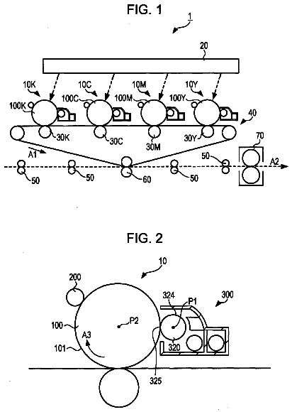
FIG. 1 is an illustrative diagram showing the overall configuration of an image forming apparatus according to the embodiment of the present invention;
FIG. 2 is an illustrative diagram showing a configuration of a fixing device of the image forming apparatus;
FIG. 3 is an illustrative diagram showing a characteristic configuration of a fixing unit according to the present embodiment;
FIG. 4 is an enlarged diagram showing the detail of part A in FIG. 3;
FIG. 5 is an illustrative diagram showing a configuration of an lenticular image formed by the fixing unit;
FIG. 6 is a block diagram showing a control system configuration of a fixing unit of the image forming apparatus; and,
FIG. 7 is an illustrative diagram showing a configuration of a variational example of a fixing unit of the present embodiment.
Description of the preferred embodiments
Now, the embodied mode for carrying out the present invention will be described with reference to the drawings.
FIG. 1 shows one example of a mode for carrying out the invention and is an illustrative diagram showing the overall configuration of an image forming apparatus according to the embodiment of the present invention. FIG. 2 is an illustrative diagram showing a configuration of a fixing device of the image forming apparatus.
An image forming apparatus 100 of the present embodiment includes: as shown in FIG. 1, photoreceptor drums 3 for forming electrostatic latent images on the surfaces thereof; chargers (charging devices) 5 for charging the photoreceptor drum 3 surfaces; an exposure unit (exposure device) 1 for forming electrostatic latent images on the photoreceptor drum 3 surfaces; developing devices 2 for supplying toners to the electrostatic latent images on the photoreceptor drum 3 surfaces to form toner images; an intermediate transfer belt unit (transfer device) 8 for transferring toner images from the photoreceptor drum 3 surfaces to a recording medium; and a fixing unit (fixing device) 12 for fixing the toner image to the recording medium. This image forming apparatus 100 that forms images with toners based on electrophotography, employs a characteristic fixing device configuration of the present invention as fixing unit 12, and forms a toner image on one side of a light transmissive recording medium and fixes an unfixed toner image to the recording medium surface while transferring and fixing a transparent resin layer to the surface opposite to that formed with an unfixed toner image to complete a lenticular lens structure.
This image forming apparatus 100 is an apparatus that forms multi-color or monochrome images on recording mediums in accordance with image data scanned from documents or image data transmitted via a network or the like.
To being with, the overall configuration of image forming apparatus 100 will be described.
As shown in FIG. 1, image forming apparatus 100 separately handles image data of individual color components, i.e., black (K), cyan (C), magenta (M) and yellow (Y), and forms black, cyan, magenta and yellow images, superimpose these images of different color components to produce a full-color image.
Accordingly, image forming apparatus 100 includes, as shown in FIG. 1, four developing devices 2 (2a, 2b, 2c and 2d), four photoreceptor drums 3 (3a, 3b, 3c and 3d), four chargers 5 (5a, 5b, 5c and 5d) and four cleaner units 4 (4a, 4b, 4c and 4d) to form images of four different colors. In other words, four image forming stations (image forming portions) each including one developing device 2, one photoreceptor drum 3, one charger 5 and one cleaner unit 4 are provided.
Here, the symbols a to d are used so that `a` represents the components for forming black images, `b` the components for forming cyan images, `c` the components for forming magenta images and `d` the components for forming yellow images. Image forming apparatus 100 also includes exposure unit 1, fixing unit 12, a sheet conveyor passage (paper conveying paths) P1, P2 and P3 and a paper feed tray 10 and a paper output tray 15.
Photoreceptor drum 3 is a roller-like member that is rotatably supported and driven on an axis thereof by means of an unillustrated driver. Photoreceptor drum 3 is an image bearer which includes a photosensitive layer and bears an electrostatic latent image and hence a toner image on the surface of the photosensitive layer.
For example, photoreceptor drum 3 can be formed of a conductive substrate made of aluminum or the like and a surface. The conductive substrate may preferably use a sleeve-like, cylindrical or sheet-like conductive base. As the photosensitive layer, an organic photosensitive layer, inorganic photosensitive layer and the like can be considered. The organic photosensitive layer may be given as a lamination type in which a charge generating layer made of a resin containing a charge generating substance and a charge transport layer made of a resin containing a charge transport substance are laminated, may be given as a mono-layer type including both a charge generating substance and a charge transport substance in a single resin layer, or may be given as a resin lamination layer including one or more kinds of the resin layers in combination. It is also preferable that a primer layer is interposed between the conductive base and the photosensitive layer. It is also preferable that a surface layer (protective layer) is formed on the photosensitive layer surface in order to protect the photosensitive layer.
Charger 5 is a member that electrifies the photoreceptor drum 3 surface at a predetermined potential of a predetermined polarity.
This charger 5 is disposed along the longitudinal direction of photoreceptor drum 3 so as to oppose photoreceptor drum 3. When the charger is of a contact charging type, charger 5 is arranged in contact with the photoreceptor drum 3 surface. When the charger is a non-contact charging type, charger 5 is arranged apart from the photoreceptor drum 3 surface.
As charger 5, a brush-type charger, roller-type charger, corona discharge device, ion generator and the like can be used.
The brush-type charger and roller-type charger are of contact charging types. The corona discharge devices include various types, specifically, a type using a wire-like discharge electrode, a type using a serrated discharge electrode, a type using a needle-shaped electrode and the like.
Exposure unit 1 illuminates the surface of photoreceptor drums 3 that have been electrified, in accordance with image data of digital signals so as to form electrostatic latent images corresponding to the image data, on the surfaces of photoreceptor drums 3. Exposure unit 1 may use a semiconductor laser device or the like. Other than the laser scanning unit, arrays of light emitting elements such as EL (electroluminescence) and LED writing heads, may also be used as exposure unit 1.
Developing device 2 includes a developing roller 114 and agitating roller 112. Developing roller 114 is a roller-shaped member that is rotatably supported on its axis. Developing roller 114 is arranged with its part projected outwards from an opening of the developing device formed on the side opposing photoreceptor drum 3 so as to be placed close to the photoreceptor drum 3 surface.
Developing roller 114 incorporates unillustrated fixed magnetic poles, which support the developer on the surface of developing roller 114 by magnetism. Developing roller 114 supplies the carried developer to the electrostatic latent image on the surface of photoreceptor drum 3 in the close area (developing nip) between developing roller 114 and photoreceptor drum 3 to thereby form a toner image on the photoreceptor drum 3 surface. Developing roller 114 rotationally driven in the opposite direction to that of photoreceptor drum 3. Accordingly, in the developing nip area, the surface of developing device 114 and the surface of photoreceptor drum 3 move in the same direction.
Developing roller 114 is connected to an unillustrated power source and applied with a d.c. voltage (developing voltage) from the power source. By this application, the developer on the developer roller 114 surface is smoothly supplied to the electrostatic latent image. The applied voltage may be superimposed with an a.c. voltage.
Developing device 2 is a receptacle member having an interior space, and its one side opposing photoreceptor drum 3 is formed with the aforementioned opening. Developing device 2 includes agitating roller 112 in the interior space and stores the developer. As the developer, a usually used developer in this field can be used. Further, the developer may be a single component developer consisting of toner only, or may be a dual component developer made up of a toner and a carrier.
Agitating roller 112 is a screw-shaped member that is rotatably supported on its axis in the interior space of developing device 2. Agitating roller 112 is rotationally driven to bring the developer in developing device 2 to or the vicinity of developing roller 114.
A developer supply container 115 is a receptacle member for storing the developer in its interior space. Developer supply container 115 supplies the developer to developing device 2 in accordance with the state of consumption of the developer in the developing device 2.
Cleaner unit 4 removes and collects the developer left on the surface of photoreceptor drum 3 after the toner image on the photoreceptor drum 3 surface has been transferred to the recording medium.
Photoreceptor charge eraser (not illustrated) erases the electricity on photoreceptor drum 3 after the leftover developer has been collected by the drum cleaner. The photoreceptor charge eraser may employ lamps, LEDs or other illumination.
Intermediate transfer belt 7 is laid out over photoreceptor drums 3 and is tensioned between a drive roller 71 and a drive roller 72, forming a loop-like moving path. Photoreceptor drum 3d, photoreceptor drum 3c, photoreceptor drum 3b and photoreceptor drum 3a are arranged in this order so as to oppose the outer peripheral surface of intermediate transfer belt 7. Primary transfer rollers 6a to 6d are disposed at positions on the opposite side to respective photoreceptor drums 3a to 3d with the intermediate transfer belt 7 therebetween. The position at which intermediate transfer belt 7 opposes each of photoreceptor drums 3a to 3d forms a primary transfer station. Intermediate transfer belt 7 is formed of a film of about 100 to 150 .mu.m thick.
In order to transfer the toner images carried on the surface of photoreceptor drums 3a to 3d to intermediate transfer belt 7, a primary transfer bias of a polarity opposite to the polarity of the electrostatic charge on the toner is applied to primary transfer rollers 6a to 6d by constant voltage control. By this voltage application the toner images of individual colors formed on photoreceptor drums 3a to 3d are successively transferred one over the other on the outer peripheral surface of intermediate transfer belt 7 so as to form a full-color toner image on the outer peripheral surface of intermediate transfer belt 7.
However, when image data for only part of four colors, yellow (Y), magenta (M), cyan (C) and black (K) is input, electrostatic latent images and hence toner images are formed on only the photoreceptor drums 3 that correspond to the colors of the input image data, among four photoreceptor drums 3a to 3d. For example, at the time of monochrome image forming, an electrostatic latent image and hence toner image is formed on only the photoreceptor drum 3a that corresponds to black color, and the black toner image alone is transferred to the outer peripheral surface of intermediate transfer belt 7.
Each of primary transfer rollers 6a to 6d is formed of a base shaft made of stainless steel having a diameter of 8 to 10 mm and a conductive material (e.g., EPDM, foamed urethane or the like) coated on the shaft surface. This conductive elastic material contributes to uniform application of a high-voltage to intermediate transfer belt 7.
The toner image transferred to the outer peripheral surface of intermediate transfer belt 7 at each primary transfer station is conveyed by rotation of intermediate transfer belt 7 to the secondary transfer station that opposes a secondary transfer roller 11. The secondary transfer roller 11 is put into pressure contact with the outer peripheral surface of intermediate transfer belt 7 under a predetermined nipping pressure, at the position where the belt's inner peripheral surface is put in contact with the peripheral surface of drive roller 71. With this arrangement, a high voltage of a polarity opposite to the polarity of the electrostatic charge on the toner is applied to secondary transfer roller 11 when the recording medium fed from a paper feed cassette 10 or a manual paper feed tray 20 passes through the nip between secondary transfer roller 11 and intermediate transfer belt 7. As a result, the toner image is transferred from the outer peripheral surface of intermediate transfer belt 7 to the recording medium surface.
Of the toner adhering from photoreceptor drums 3 to intermediate transfer belt 7, the toner that has not been transferred to the recording medium but remains on intermediate transfer belt 7 is collected by a transfer cleaning unit 9 in order to prevent contamination of colors in the next operation.
The recording medium with the toner image transferred thereon is lead to fixing unit 12, and heated and pressurized by being passed through a fixing nip portion 12c formed between a fixing belt 64 tensioned between a fixing roller 12a and a heating roller 60 and a pressing roller 12b. As a result, the toner image is robustly fixed to the recording medium surface. The recording medium fixed with the toner image is discharged onto paper output tray 15 by means of a paper output roller 253.
Arranged in image forming apparatus 100 is a paper conveying passage P1 that extends in an approximately vertical direction in order to convey a recording medium stored in paper feed cassette 10 through the nip between secondary transfer roller 11 and intermediate transfer belt 7 and fixing unit 12 to paper output tray 15.
Arranged along paper conveying passage P1 are a pickup roller 161 for delivering sheet-like recording mediums one sheet at a time from paper feed cassette 10 to paper conveying passage P1, conveying rollers 251 for conveying the delivered recording medium upwards, a registration roller 14 that leads the conveyed recording medium towards the nip between secondary transfer roller 11 and intermediate transfer belt 7 at a predetermined timing, and paper output roller 253 for discharging the recording medium to paper output tray 15.
Also, a paper conveying passage P2 along which a pickup roller 162, conveying rollers 254, 255 and 256 are laid out is formed from manual paper feed tray 20 to registration roller 14. Further, a paper conveying passage P3 is formed from paper output roller 253 to the upstream side of registration roller 14 in paper conveying passage P1.
Paper output roller 253 is adapted to rotate in both forward and reverse directions. The paper output roller is turned in the forward direction so as to discharge the recording medium to paper output tray 15, in one-sided image forming mode in which image forming is performed on one side of the recording medium and when image forming is performed on the second side of the recording medium in duplex image forming mode in which images are formed on both sides of the recording medium. On the other hand, at the time of image forming on the first side in the duplex image forming mode, paper output roller 253 is driven in the forward direction until the rear end of the recording medium passes through fixing unit 12 and then driven in reverse from the state in which the paper output rollers hold the rear end of the recording medium, so as to lead the recording medium into paper conveying passage P3. As a result, the recording medium with an image formed on one side in the duplex image forming mode is turned upside down with the front side inverted to the rear, and drawn to paper conveying passage P1 by means of conveying rollers 257 and 258.
Registration roller 14 delivers the recording medium, fed from paper feed cassette 10, or manual paper feed tray 20, or conveyed by way of paper conveying passage P3, to the nip between secondary transfer roller 11 and intermediate transfer belt 7 at a timing in synchronization with the rotation of intermediate transfer belt 7. For this purpose, registration roller 14 is suspended to rotate when photoreceptor drums 3 and intermediate transfer belt 7 start operating, and the recording medium that has been fed or conveyed ahead of the rotation of intermediate transfer belt 7, puts its front edge against registration roller 14 and stops moving in paper conveying passage P1. Then, registration roller 14 starts rotating at such a timing that the front end of the recording paper and the front end of the toner image formed on intermediate transfer belt 7 will meet each other at the pressure nip between secondary transfer roller 11 and intermediate transfer belt 7.
Here, in full-color image forming mode in which all the image forming portions Pa to Pd are used to perform image forming, primary transfer rollers 6a to 6d are caused to bring intermediate transfer belt 7 into pressing contact with all the photoreceptor drums 3a to 3d. On the other hand, in monochrome image forming mode in which image forming portion Pa alone is used to perform image forming, primary transfer roller 6a alone is caused to press intermediate transfer belt 7 against photoreceptor drum 3a.
Fixing unit 12 includes, as shown in FIG. 2, fixing roller 12a, pressing roller 12b, fixing belt 64 and heat roller 60 as a heating member. Arranged inside heat roller 60 is a heater lamp 66 for heating heat roller 60. Fixing belt 64 is suspended between fixing roller 12a and heat roller 60 while pressing roller 12b is arranged so as to oppose fixing roller 12a with fixing belt 64 in between.
Designated at a reference numeral 12d is a separation claw that peels off the recording medium stuck to pressing roller 12b.
Fixing roller 12a and heat roller 60 are arranged approximately parallel to each other in the axial direction of fixing roller 12a. Accordingly, when fixing belt 64 suspended between fixing roller 12a and heat roller 60 moves whilst sliding, it is possible to prevent the belt from traveling in a skewed manner and keep durability of fixing belt 64 high.
Fixing unit 12 is a fixing device in which heat roller 60 comes in contact with fixing belt 64 to heat fixing belt 64, and when a recording medium, designated at 82, passes through fixing nip portion 12c formed between fixing belt 64 and pressing roller 12b, at a predetermined fixing speed and copy speed, the unfixed toner image, designated at 81, supported on recording medium 82 is heated and pressed on recording medium 82 to thereby achieve fixing.
Here, unfixed toner image 81 may be formed of a developer (toner) such as, for example, a non-magnetic mono component developer (non-magnetic toner), non-magnetic dual component developer (non-magnetic toner and carrier), magnetic developer (magnetic toner) or the like. The fixing speed is the so-called process speed, and the copy speed means the number of copies per minute.
Fixing belt 64 is arranged so as to abut the toner image supporting side of recording medium 82 when recording medium 82 passes through fixing nip portion 12c.
Fixing roller 12a is rotatably arranged on its rotation axis so as to oppose pressing roller 12b with fixing belt 64 in between whilst forming fixing nip portion 12c by abutting fixing belt 64 against pressing roller 12b. Fixing roller 12a is driven by rotation of pressing roller 12b to rotate in a rotational direction Y1.
Detailedly, fixing roller 12a is 30 mm in diameter, has a two-layered structure composed of a metal core and an elastic layer in this order from the interior side. The metal core may be formed of a metal such as iron, stainless steel, aluminum, copper or the like, or an alloy of these. As the elastic layer, heat-resistant rubber material such as silicone rubber, fluoro rubber or the like is preferably used. In the present embodiment, the force of fixing roller 12a pressing on pressing roller 12b via fixing belt 64 is about 216 N.
Pressing roller 12b is rotationally driven in a rotational direction of Y2 about the rotational axis by means of an unillustrated drive motor (driver) to convey fixing belt 64.
Detailedly, pressing roller 12b has a two-layered structure composed of a metal core and a release layer in this order from the interior side. The metal core may be formed of a metal such as iron, stainless steel, aluminum, copper or the like, or an alloy of these. As the release layer of the pressing roller, fluoro resins such as PFA (tetra fluoro ethylene-perfluoro alkylvinyl ether copolymer), PTFE (polytetrafluoroethylene) and the like are preferably used. A heater lamp 66 for heating pressing roller 12b is arranged inside pressing roller 12b.
Further, a cleaning mechanism 13 for removing toner adhering to pressing roller 12b is provided at a position around pressing roller 12b.
The description continues in the full USPTO document.
 Lapsed, fee not paid11 drawings