Lapsed, fee not paid4 drawings
Telecom & Networks · US 8,675,534 B2
Method and system for realizing carrier control
The present disclosure provides a method and system for realizing a carrier control.
US 8,675,554 B2 · Assignee: Intel Corporation · Inventors: Baglin; Matthieu Richard Joachim et al.
Sheet 1 of 11 from the published document. All sheets in the USPTO PDF
A wireless communication device is operable to perform neighbor cell analysis functions while operating in a continuous packet connectivity (CPC) mode and without requiring dedicated time periods for performing the neighbor cell analysis functions as part of a discontinuous reception (DRX) phase of the CPC mode. The DRX phase includes discontinuous (e.g., periodic) time periods for monitoring a downlink control channel from a serving base station. A receiver of the wireless communication device receives a control signal over the downlink control channel during each time period of the discontinuous time periods. A processor of the wireless communication device performs a portion of a neighbor cell analysis function during each time period of a quantity of the discontinuous time periods to produce neighbor cell analysis data. The processor accumulates the neighbor cell analysis data over the quantity of time periods to complete the neighbor cell analysis function.
Wireless communication networks are well known. Some networks are completely proprietary, while others are subject to one or more standards to allow various vendors to manufacture equipment for a common system. Standards-based networks include networks, such as the Universal Mobile Telecommunications System (UMTS), the Global System for Mobile Communications (GSM) and its progeny (e.g., the General Packet Radio Service (GPRS) and the Enhanced Data rates for GSM Evolution (EDGE)), and the Long Term Evolution (LTE) system developed by the Third Generation Partnership Project (3GPP), a collaboration between groups of telecommunications associations to make globally applicable third generation (3G) mobile phone system specifications within the scope of the International Mobile Telecommunications-2000 project of the International Telecommunication Union (ITU). The 3GPP has adopted Wideband Co
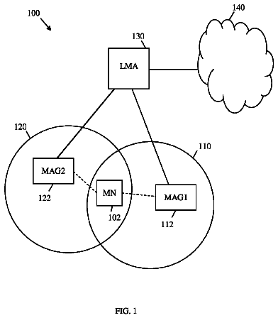
1 of 11 drawing sheets so far from the published document, cropped to the drawing. Every sheet is in the USPTO PDF.
What the patent claimed, word for word. All of it is now free to use.
The present invention relates generally to wireless communication networks and, more particularly, to a wireless communication device and method for operating same to perform neighbor cell analysis functions as part of a discontinuous reception (DRX) phase of a continuous packet connectivity (CPC) mode without requiring dedicated time periods for performing such neighbor cell analysis functions.
Wireless communication networks are well known. Some networks are completely proprietary, while others are subject to one or more standards to allow various vendors to manufacture equipment for a common system. Standards-based networks include networks, such as the Universal Mobile Telecommunications System (UMTS), the Global System for Mobile Communications (GSM) and its progeny (e.g., the General Packet Radio Service (GPRS) and the Enhanced Data rates for GSM Evolution (EDGE)), and the Long Term Evolution (LTE) system developed by the Third Generation Partnership Project (3GPP), a collaboration between groups of telecommunications associations to make globally applicable third generation (3G) mobile phone system specifications within the scope of the International Mobile Telecommunications-2000 project of the International Telecommunication Union (ITU).
The 3GPP has adopted Wideband Code Division Multiple Access (WCDMA) as the wireless air interface access for the UMTS network. WCDMA provides high frequency spectrum utilization, universal coverage, and high quality, high-speed multimedia data transmission. When operating over a 3G mobile telecommunications system, such as UMTS, a user can utilize a wireless communications device, such as a mobile phone, to engage in real-time video communications and conference calls, play real-time games, receive online music broadcasts, and send/receive email. However, because these functions rely on fast, instantaneous transmission, 3G systems utilize technologies, such as High Speed Packet Access (HSPA), which includes High Speed Downlink Packet Access (HSDPA) and High Speed Uplink Packet Access (HSUPA), to improve uplink/downlink transmission rate.
In order to improve HSDPA and HSUPA, Release 7 (R7) of the 3GPP standard provides a Continuous Packet Connectivity (CPC) protocol specification, which includes features that aim to significantly increase the number of packet data users per cell, reduce the uplink noise level resulting from such increase in packet data users, reduce power consumption at the user equipment (UE) (e.g., mobile device), and improve the achievable download capacity for various data services, such as Voice over Internet Protocol (VoIP).
According to the CPC protocol specification, discontinuous transmission (DTX) and discontinuous reception (DRX) operation is used by the UE, such as a smart phone, when transmissions between the UE and the serving base station (e.g., enhanced Node B or eNodeB) are decreasing. The DTX-DRX operation includes discontinuous uplink transmission (uplink DTX) and discontinuous downlink reception (downlink DRX). Uplink DTX is a mechanism where control signals are transmitted on the uplink control channels (e.g., the Uplink Dedicated Physical Control Channel (UL-DPCCH)) according to defined discontinuous patterns during the inactive state of corresponding uplink data channels, such as an Enhanced Dedicated Transport Channel (E-DCH) or a High Speed Physical Control Channel (HS-DPCCH), in order to maintain signal synchronization and power control loop with less control signaling. For example, uplink DTX allows the UE to align UL-DPCCH transmission with a fixed DTX pattern to maintain UE synchronization with the network. Downlink DRX is configured by a Radio Network Controller (RNC), which may form part of the serving base station, and allows the UE to restrict the downlink reception times in order to reduce power consumption. When the downlink DRX is enabled, the UE is not required to receive physical downlink channels except during pre-established time intervals.
According to prior art downlink DRX approaches in the context of CPC during HSPA data transfer, the UE receiver is activated periodically (e.g. every DRX period, which can vary from 8 to 40 milliseconds (ms)) to perform certain tasks. For example, during each active period, the UE may receive a downlink control channel, such as the High Speed Shared Control Channel (HS-SCCH), and process the received control signals to determine whether the serving base station has data to send to the UE. If the UE determines that the serving station has user data to send, the UE keeps its receiver activated so as to be able to receive the data from the serving station. After the data has been received, the UE may keep the receiver activated for an additional period of time according to an inactivity timer in case additional control information or user data is sent.
In addition to being periodically activated or awakened to monitor for data transmission notifications, the UE receiver is also typically activated during dedicated time periods to perform intra-frequency neighbor cell analysis functions so as to determine whether to select a new cell for communication. Depending on network configuration, neighbor cell analysis functions may include, among other things, detecting the presence of neighbor cells belonging to a monitored set and monitoring channel qualities of neighbor cells. The neighbor cell detection function typically occurs in multiple stages and includes receiving primary synchronization channels (stage 1), receiving secondary synchronization channels (stage 2), determining scrambling codes (stage 3), and decoding system frame numbers (SFN) (stage 4). According to 3GPP R7 Technical Specification (TS) 25.133, section 8.1.2.2.2, when DRX is active and the DRX cycle is less than ten subframes (e.g., less than 20 ms where each subframe has a 2 ms duration), the UE must identify and decode the SFN of a new cell in the monitored list within 800 ms. Alternatively, where the DRX cycle is greater than ten subframes, the UE must identify and decode the SFN of a new cell in the monitored list within 1.5 seconds.
In the context of 3GPP TS 25.133, section 8.1.2.2.2, the subframes referred to therein are generally used for monitoring the HS-SCCH of the serving cell in order to detect whether the serving base station has data to send to the UE as part of a continuing data session. Other channels, such as the Fractional Downlink Dedicated Physical Channel (F-DPCH), may also be monitored for power control purposes. To facilitate intra-frequency neighbor cell analysis, the DRX phase of CPC typically includes additional dedicated time periods which exceed the subframe duration and can extend beyond a DRX cycle (e.g., longer than 40 ms) depending on the quantity of neighbor cells to be detected and analyzed. Exemplary DTX-DRX operation is illustrated by the waveform 100 of FIG. 1. In the exemplary waveform 100, the DRX cycle between activations of the UE receiver for serving cell monitoring is 40 ms (e.g., as noted between signals 102 and 103) and the DTX cycle between activations of the UE transmitter is 320 ms (e.g., as noted between signals 105 and 106). Exemplary dedicated time periods for performing intra-frequency neighbor cell analysis are illustrated by signal waveforms 107-112, each of which is illustrated as lasting about 40 ms. While such additional dedicated time periods enable the UE receiver to perform necessary neighbor cell analysis, they also require the UE receiver to be powered on and activated, thereby utilizing valuable UE battery resources and undesirably shortening the time period between required battery recharging.
To facilitate analysis of neighbor cells other than intra-frequency neighbor cells (e.g., cells which do not operate in the same frequency band as the serving cell or operate using a different wireless protocol, such as inter-frequency neighbor cells or cells utilizing the Global System for Mobile Communications (GSM) protocol), 3GPP R7 TS 25,212 provides for a so-called "compressed mode" of operation that introduces transmission gaps in what would otherwise be allocated transmission subframes. The transmission gaps temporarily halt UE transmissions and their associated downlink power control messaging to enable the UE receiver to monitor inter-frequency or other off-frequency neighbor cells instead of power control or other control signaling from the serving cell. To be compliant with the 3GPP specification, any battery-saving solution relating to CPC should preferably be compatible with compressed mode operation.
FIG. 1 illustrates an exemplary received signal waveform during CPC mode DTX-DRX operation of a prior art wireless communication device.
FIG. 2 illustrates a wireless communication system in accordance with an exemplary embodiment of the present invention.
FIG. 3 illustrates an electrical block diagram of an exemplary wireless communication device in accordance with the present invention.
FIG. 4 is a logic flow diagram of steps executed by a wireless communication device to perform neighbor cell analysis while operating in CPC mode in accordance with one exemplary embodiment of the present invention.
FIG. 5 is a timing diagram illustrating allocations of time slots and subframes of various uplink and downlink control channels during CPC mode, without compressed mode, operation of a wireless communication device in accordance with one exemplary embodiment of the present invention.
FIG. 6 illustrates a received signal waveform during exemplary CPC mode DTX-DRX operation of a wireless communication device in accordance with one embodiment of the present invention.
FIGS. 7A-7B are a logic flow diagram of steps executed by a wireless communication device to perform neighbor cell analysis while operating in CPC and compressed modes in accordance with another exemplary embodiment of the present invention.
FIG. 8 is a timing diagram illustrating allocations of time slots and subframes of various uplink and downlink control channels during CPC and compressed mode operation of a wireless communication device, where a compressed mode gap does not overlap a time period for monitoring a serving cell's downlink control channel, in accordance with another exemplary embodiment of the present invention.
FIG. 9 is a timing diagram illustrating allocations of time slots and subframes of various uplink and downlink control channels during CPC and compressed mode operation of a wireless communication device, where a compressed mode gap overlaps a time period for monitoring a serving cell's downlink control channel, in accordance with a further exemplary embodiment of the present invention.
FIG. 10 is a timing diagram illustrating allocations of time slots and subframes of various uplink and downlink control channels during CPC and compressed mode operation of a wireless communication device, where a compressed mode gap overlaps both a time period for monitoring a serving cell's downlink control channel and a transmission time period for transmitting uplink control information to the serving cell, in accordance with yet another exemplary embodiment of the present invention.
Skilled artisans will appreciate that elements in the figures are illustrated for simplicity and clarity and have not necessarily been drawn to scale. For example, the dimensions of some of the elements in the figures may be exaggerated alone or relative to other elements to help improve the understanding of the various embodiments of the present invention.
Generally, the present invention encompasses a wireless communication device and associated method for performing neighbor cell analysis functions while operating in a continuous packet connectivity (CPC) mode and without requiring dedicated time periods for performing the neighbor cell analysis functions as part of a discontinuous reception (DRX) phase of the CPC mode. The wireless communication device, which preferably includes a receiver, a processor, and optionally a transmitter, may be a computer, a smart phone, a cellular phone, a handheld game system, a wireless data card, or any other electronic device that provides or facilitates mobile wireless communication functionality. The DRX phase includes discontinuous time periods for monitoring a downlink control channel, such as a High Speed Shared Control Channel (HS-SCCH), from a serving base station. A receiver of the wireless communication device receives a control signal over the downlink control channel during each time period of the discontinuous time periods. A processor of the wireless communication device, operating in accordance with a set of stored operating instructions, performs a portion of a neighbor cell analysis function during each time period of a quantity of the discontinuous time periods to produce neighbor cell analysis data. In one embodiment, the portion of the neighbor cell analysis function performed during each time period of the quantity of discontinuous time periods pertains to analysis of intra-frequency neighbor cells (i.e., cells operating at the same center frequency, in the same bandwidth, and with the same wireless, physical layer protocol as the cell currently serving the wireless communication device). The processor accumulates the neighbor cell analysis data over the quantity of time periods to complete the neighbor cell analysis function. In other words, the neighbor cell analysis data is acquired over a quantity of time periods instead of all at once over a dedicated time period, thereby eliminating the need for separate, dedicated neighbor cell monitoring periods (especially intra-frequency neighbor cell monitoring periods).
In an alternative embodiment, the wireless communication device may also include a transmitter operable to transmit control information to the serving base station over an uplink control channel. Additionally, uplink power control information may be transmitted by the serving base station to the wireless communication device over a second downlink control channel. In such an embodiment, the wireless device transmitter transmits control information to the serving base station during a transmission period and the wireless device receiver receives uplink power control information from the serving base station during at least the transmission period to facilitate uplink power control operations of the wireless communication device. For example, where the second downlink control channel and the uplink control channel are divided into respective time slots and the transmission period occupies a set of uplink time slots, the uplink power control information is received by the wireless device receiver during a set of downlink time slots which overlaps the set of uplink time slots in time. Where the wireless communication device is operating in a wireless system implementing the 3GPP standard, the second downlink control channel is a Fractional Dedicated Physical Channel (F-DPCH), and the uplink control channel is an Uplink Dedicated Physical Control Channel (UL-DPCCH), the set of uplink time slots carrying the uplink control information may include a synchronization burst together with a preamble and a postamble. In such a case, the transmission period may form part of a discontinuous transmission (DTX) phase of the CPC mode.
In yet another embodiment, the wireless communication device may be programmed or otherwise configured to monitor and/or analyze cells other than intra-frequency neighbor cells (e.g., inter-frequency neighbor cells or neighbor cells utilizing a different physical layer protocol, such as the Global System for Mobile Communications (GSM) protocol or Long Term Evolution (LTE) protocol) during assigned cell monitoring periods that may wholly or partially overlap the time periods (e.g., slots) during which the wireless device receiver is monitoring the downlink control channel of the serving cell. In accordance with one embodiment, the wireless device receives control signals of neighbor cells other than intra-frequency neighbor cells over respective downlink control channels during the assigned cell monitoring periods to produce received off-frequency neighbor cell control signals. The wireless device processes (e.g., demodulates and decodes) the off-frequency neighbor cell control signals to produce off-frequency neighbor cell control data and performs neighbor cell analysis functions (e.g., neighbor cell identification, downlink signal quality determination, and so forth) based on the off-frequency neighbor cell control data. When a time window assigned to an off-frequency cell monitoring period overlaps a time window assigned to receive or monitor the downlink control channel of the serving cell, the wireless device may reassign the time window assigned to monitor the downlink control channel of the serving cell such that the time window assigned to the off-frequency cell monitoring period does not overlap the time window assigned to monitor the downlink control channel of the serving cell. In one particular embodiment in which the downlink control channel of the serving cell is divided into subframes, the wireless device may reassign the time period for monitoring the downlink control channel of the serving cell to a subframe of the downlink control channel which commences after cessation of the period assigned to receiving or monitoring control signals of the off-frequency neighbor cells.
In another embodiment in which the wireless communication device transmits control information to the serving base station over an uplink control channel and receives uplink power control information from the serving base station over a second downlink control channel, a time window assigned to an off-frequency cell monitoring period may overlap and form part of a so-called "connection frame" with a time window assigned for the wireless device to transmit control information over the uplink control channel. In such a case, the wireless device may transmit control information over the uplink control channel during the connection frame and prior to commencement of the time window assigned to the off-frequency cell monitoring period. The wireless device may then temporarily cease transmission of control information over the uplink control channel during at least part of the time window assigned to the off-frequency cell monitoring period and continue transmission of the control information over the uplink control channel for a remainder of the connection frame after cessation of the off-frequency cell monitoring period. In addition to temporarily ceasing transmission of uplink control information, the wireless device may cease reception of uplink power control information from the serving base station during the time window assigned to the off-frequency cell monitoring period and receive uplink power control information from the serving base station during time periods when control information is being transmitted over the uplink control channel. In this embodiment, when a time window assigned to an off-frequency cell monitoring period also overlaps a time window assigned to a time period for receiving or monitoring the downlink control channel from the serving cell, the wireless device may reassign the time window assigned for monitoring the downlink control channel from the serving cell such that the time window assigned to the off-frequency cell monitoring period does not overlap the time window assigned for monitoring the downlink control channel from the serving cell.
In one embodiment, the assigned cell monitoring periods coincide with transmission gaps introduced during operation of a compressed mode as specified in 3GPP R7 TS 25.212, which may be used in conjunction with CPC mode. When compressed mode is used, the transmission gaps are inserted into what would otherwise be allocated transmission subframes in order to temporarily halt wireless device (e.g., user equipment (UE)) transmissions and their associated downlink power control messaging to enable the wireless device receiver to monitor or otherwise analyze inter-frequency or other off-frequency neighbor cells instead of power control or other control signaling from the serving cell.
In a further embodiment, the neighbor cell analysis functions that may be performed by the wireless communication device include, but are not limited to, measuring channel quality of a downlink control channel supplied by a base station servicing a neighbor cell (e.g., a so-called "intra-frequency cell" neighboring the serving cell serviced by the serving base station and operating in the same frequency band and with the same wireless protocol as the serving cell), decoding a primary synchronization signal communicated by a base station servicing a neighbor cell, decoding a secondary synchronization signal communicated by a base station servicing a neighbor cell, and determining a scrambling code for a neighbor cell. Accordingly, the wireless communication device may at least partially measure neighbor cell channel quality, decode neighbor cell primary synchronization signals, decode neighbor cell secondary synchronization signals, and/or determine neighbor cell scrambling codes during each discontinuous serving cell monitoring period. If a sufficient amount of time is collectively configured for performing neighbor cell analysis, the wireless device may also decode the system frame number (SFN) for each neighbor cell.
In yet another embodiment, the reception and transmission operations of the wireless device may be implemented in a discontinuous manner so as to support DRX operation and discontinuous transmission (DTX) operation according to the 3GPP specification for CPC mode. In this case, the wireless device processor maintains timers for activating the wireless device receiver and transmitter according to the established DTX/DRX phases. In accordance with a DRX phase, the wireless device processor activates the previously deactivated wireless device receiver upon commencement of a serving cell control channel monitoring period and prior to receiving a control signal over the monitored downlink control channel. Additionally, the wireless device processor deactivates the wireless device receiver upon expiration of the serving cell control channel monitoring period in the event that the control signal received during the period does not indicate that the serving base station has user data to send to the wireless communication device. On the other hand, if the control signal received during the serving cell control channel monitoring period indicates that the serving base station has user data to send to the wireless communication device, the wireless device processor maintains activation of the wireless device receiver so as to receive the user data over an appropriate data traffic channel (e.g., a High Speed Downlink Physical Shared Channel (HS-DPSCH)).
By using time periods assigned in the DRX phase of CPC mode for monitoring the serving cell's downlink control channel to also perform portions, of the neighbor cell analysis function, the present invention enables the wireless device to complete the neighbor cell analysis function over time without requiring separate, dedicated neighbor cell analysis time periods. In this manner, the present invention reduces the total amount of time the wireless device's receiver is on during the DRX phase, thereby conserving battery power and extending the time between required battery charges.
Embodiments of the present invention can be more readily understood with reference to FIGS. 2-10, in which like reference numerals designate like items. FIG. 2 is an electrical block diagram of a wireless communication system 200 in accordance with an exemplary embodiment of the present invention. The wireless system 200 includes one or more wireless communication devices 201 (one shown), a plurality of base stations 203-206 (four shown), and various other conventional infrastructure components (e.g., radio network controllers, home and visitor location registers, a mobile switching center) that facilitate communication within the wireless communication system 200 and between the wireless communication system 200 and other communications systems, such as the public switched telephone network (PSTN) and the Internet. Each base station provides wireless communication service to at least a portion of a respective service coverage area 207-210, which is typically referred to as a "cell." In one embodiment, each cell 207-210 may be subdivided into sectors (e.g., three sectors of 120 degrees each). In such a case, each sector of the cell 207-210 may be serviced by one or more base stations.
Typically, a wireless device 201 located in a particular cell 207 is supplied communication service from one base station 203, which is referred to herein as a "serving base station" or "serving cell." However, in certain systems or under certain circumstances (e.g., soft handoff), a wireless device may be serviced by multiple base stations at the same time. Base stations 204-206 providing communication service to cells 208-210 adjacent the cell 207 in which the wireless device 201 is located are referred to herein as "neighbor or neighboring base stations" or "neighbor cells." During operation of the wireless device 201 in the wireless system 200, the wireless device 201 exchanges control data and traffic or user data with the currently serving base station 203 according to the particular wireless protocol employed in the system 200. In one embodiment, the wireless system 200 employs the High Speed Packet Access (HSPA) protocol operating over a Wideband Code Division Multiple Access (WCDMA) air interface, as specified in Release 7 of the 3GPP specification. In such an embodiment, each base station 203-206 may be referred to as a "Node B," an enhanced Node B, an eNodeB, or an eNB to conform with 3GPP terminology. Alternatively, the wireless system 200 may employ the Evolution Data Only/Evolution Data Optimized (EVDO) protocol operating over a CDMA air interface. Additionally, the wireless device 200 regularly receives control signals from neighboring base stations 204-206 to enable the wireless device 201 to determine, or at least assist in determining, which neighboring base station 204-206 would be best suited to continue supplying communication service to the wireless device 201 in the event that the wireless device 201 moved out of the coverage range of the currently serving base station 203 (i.e., after a handoff).
FIG. 3 is an electrical block diagram of an exemplary embodiment of the wireless communication device 201. The exemplary wireless communication device 300 includes, inter alia, a processor 301, at least one storage device (e.g., memory 303), a direct current (DC) power source (e.g., a rechargeable battery 304), a receiver 305, a transmitter 307, a display 309, a user interface 311, an alerting mechanism 313, and one or more antennas 315, 317-318 (three shown). As illustrated, the processor 301 is operably coupled to the memory 303, the receiver 305, the transmitter 307, the display 309, the user interface 311, and the alerting mechanism 313. The battery 304 supplies DC power to all the components of the wireless device 201 which require such power. The wireless device 201 may optionally include various other elements, such as input/output ports (which may be wired or wireless interfaces, such as Universal Serial Bus (USB), MP3, Wi-Fi, and/or Bluetooth interfaces) and an external memory interconnect 315 to interface with a separate, transportable external memory device 317 (e.g., a USB flash drive, a flash memory card, a subscriber identification module (SIM) card, or any other portable storage device). When included, the optional components 307-315 are operably coupled to and controlled directly or indirectly by the processor 301.
The wireless communication device 201 may be any device or user equipment (UE) capable of communicating data over a wireless communication system 200 and operating in a continuous packet connectivity (CPC) mode similar to the CPC mode described in the 3GPP standard. Accordingly, the wireless device 201 may be a smart phone, a cellular phone, a mobile phone, a two-way radio, a wireless messaging device, a computer with an embedded or attached wireless modem or air card (e.g., a netbook computer, an "iPAD" computer, a notebook computer, a laptop computer, or a palmtop computer), a personal digital assistant (PDA), a wireless email device, a handheld or portable gaming device including a an embedded or attached wireless modern, a portable DVD player including a an embedded or attached wireless modem, or any other mobile wireless data-capable device.
The processor 301 may be a microprocessor, a microcontroller, a digital signal processor (DSP), a state machine, logic circuitry, or any other device or combination of devices that processes information based on operating or programming instructions stored in the memory 303. One of ordinary skill in the art will appreciate that the processor 301 can be implemented using multiple processors as may be required to handle the processing requirements of the present invention and the various other included functions of the wireless device 201. One of ordinary skill in the art will further recognize that when the processor 301 has one or more of its functions performed by a state machine or logic circuitry, the memory containing the corresponding operational instructions can be embedded within the state machine or logic circuitry as opposed to being external to the processor 301, as is the wireless device's internal memory 303 illustrated in FIG. 3. In one embodiment, the processor 301 controls substantially all the functionality of the wireless device 201.
The wireless device's internal memory 303 stores, inter alia, the operating instructions 314 used by the processor 301 to control operation of the various components of the wireless device 201, including the operating instructions necessary to perform neighbor cell analysis functions while the wireless device 201 is operating in CPC mode as described in more detail below with respect to FIGS. 4-10. The memory 303 may be separate from the processor 301 as depicted in FIG. 3 or integrated into the processor 301 as noted above. The memory 303 can include random access memory (RAM), read-only memory (ROM), flash memory, electrically erasable programmable read-only memory (EEPROM), and/or various other forms of memory as are well known in the art. It will be appreciated by one of ordinary skill in the art that the various memory components can each be a group of separately located memory areas in the overall or aggregate device memory 303 and that the device memory 303 may include one or more individual memory elements.
The receiver 305 and the transmitter 307 may comprise any conventional hardware and software for communicating control and user data, including voice communications, between the wireless device 201 and base stations 203-206 providing communication service to the wireless device 201. Depending on the wireless protocol(s) chosen for the wireless system(s) 200 in which the wireless device 201 can operate, the receiver 305 and the transmitter 307 may support one or more wireless communication protocols, such as Wi-Fi (e.g., IEEE 802.11 a/b/g/n), WiMax (e.g., IEEE 802.16), Ultra Wide-Band (e.g., IEEE 802.15.4a draft standard), CDMA, wideband CDMA, time division multiple access (TDMA), Global System for Mobile Communications (GSM), Enhanced Data GSM Environment (EDGE), General Packet Radio Service (GPRS), frequency division multiple access (FDMA), orthogonal frequency division multiplexing (OFDM), Long Term Evolution (LTE), spread spectrum, or any other known or future developed access or link protocol or methodology, which supports CPC or a similar mode of operation. The receiver 305 and the transmitter 307 may include multiple receivers and transmitters when multiple link technologies are employed by the wireless device 201. Additionally, where the receiver 305 supports single input, multiple output (SIMO) and/or multiple input, multiple output (MIMO) functionality as supported by HSPA and LTE protocols, the wireless device 201 may include two or more receive antennas 317-318 (two shown for illustration). Alternatively or additionally, multiple receive antennas may be included where the receiver 305 is a multi-mode receiver supporting reception of signals transmitted using different air interfaces (e.g., WCDMA and GSM, or CDMA and WCDMA). Further, whereas the depicted wireless device 201 includes only a single transmit antenna 315, one or more additional transmit antennas may be used where the transmitter 307 supports MIMO functionality and/or the transmitter 307 is a multi-mode transmitter supporting transmission of signals using different air interfaces.
The display 309 may be any conventional or future-developed display, such as a liquid crystal display (LCD), a plasma display, a light emitting diode (LED) display, an organic LED (OLED) display, or any other display technology. The display 309 includes appropriate conventional drivers and may optionally include graphics processors for illuminating various portions (e.g., pixels) of a display screen as instructed by the processor 301. The user interface 307 may be any conventional user interface or combination of conventional user interface components, such as rocker keys, buttons, a keypad, a keyboard, a scroll wheel, a thumbwheel, one or more microphones and associated speech conversion/processing software, one or more speakers, a touchpad, a touchscreen incorporated into a display screen of the display 309, or any other now known or future-developed user interface technology.
The alerting mechanism 313 may include a vibration device, a speaker with appropriate drive circuitry, and/or LEDs or other visual notification means with appropriate drive circuitry, or utilize some or all of the user interface 311 under the control of the processor 301 to alert the wireless device user of the arrival of an incoming message or call. Such an alerting mechanism is generally known in the art.
Operation of the wireless device 201 in accordance with the present invention to perform neighbor cell analysis functions while operating in a CPC mode without requiring dedicated time periods for performing the neighbor cell analysis functions as part of the DRX phase of the CPC mode may be best understood with reference to FIGS. 4-10. FIGS. 4-6 illustrate operation of the wireless device 201 in accordance with embodiments of the present invention during periods when compressed mode under 3GPP R7 TS 25.212 is not in use; whereas, FIGS. 7-10 illustrate operation of the wireless device 201 in accordance with embodiments of the present invention during periods when compressed mode is in use.
Referring first to FIG. 4, a logic flow diagram 400 is depicted illustrating steps executed by a wireless communication device 201 to perform neighbor cell analysis while operating in CPC mode in accordance with one exemplary embodiment of the present invention. The logic flow steps may be executed by the wireless device processor 301 and receiver 305. Execution of logic flow steps by the wireless device processor 301 is preferably in accordance with the operating instructions 314 stored in device memory 303.
According to the logic flow of FIG. 4, the wireless device processor 301 activates
a previously de-activated wireless device receiver 305 upon commencement of a serving cell monitoring period according to a DRX phase of the CPC mode. As is generally known in the art, the DRX phase of the CPC mode includes multiple discontinuous time periods for the wireless device 201 to monitor a downlink control channel from the serving cell base station 203 (e.g., the HS-SCCH where the wireless system 200 utilizes HSPA) to determine whether the serving base station 203 has user data to send to the wireless device 201. When compressed mode is not in use, the serving cell monitoring periods occur periodically and generally have a duration of at least two milliseconds. When compressed mode is in use, the serving cell monitoring periods may or may not occur periodically depending upon the positioning of the compressed mode gaps, as will be described in more detail below with respect to FIGS. 7-10. The actual duration of each serving cell monitoring period is established by the service provider of the wireless system 200 and is communicated to the wireless device 201 via control messaging from the serving base station 203. For example, in one embodiment, each serving cell monitoring period commences every eight milliseconds and is two milliseconds in duration for a total DRX cycle of eight milliseconds. Where the wireless system 200 utilizes HSPA over a WCDMA air interface, each serving cell monitoring period may occupy three time slots or one subframe on the HS-SCCH and occur once every four subframe DRX cycle for the duration of the DRX phase. Alternatively, the wireless service provider (carrier) may establish a longer duration serving cell monitoring period with a different periodicity taking into account the particular characteristics of the wireless system 200. In contrast to a conventional DRX phase of CPC mode operation, the present invention makes further use of serving cell monitoring periods to perform neighbor cell monitoring (especially intra-frequency neighbor cell monitoring) so as to eliminate, or mitigate the time duration of, dedicated neighbor cell monitoring periods during the DRX phase. The elimination or mitigation of such dedicated neighbor cell monitoring periods serves to reduce the amount of time that the wireless device receiver 305 must remain on and thereby extends the life (or time between charges) of the wireless device battery 304.
FIG. 5 shows a timing diagram 500 illustrating allocations of time slots and subframes of various uplink and downlink control channels during CPC mode, without compressed mode, operation of a wireless communication device 201 in accordance with the above-described exemplary embodiment of the present invention. The timing diagram 500 of FIG. 5 will be referenced throughout the description of FIG. 4 to provide an exemplary, but not exclusive, context for understanding operation of the present invention during times when compressed mode operation does not impact CPC mode operation. The timing diagram 500 of FIG. 5 is for a wireless system 200 that utilizes HSPA over a WCDMA air interface. Thus, the depicted downlink control channels are the HS-SCCH, over which user data transmission is scheduled by the serving base station 203, and a Fractional Dedicated Physical Channel (F-DPCH), over which power control information is provided to the wireless device 201 by the serving base station 203. The downlink traffic channel is the High Speed Physical Downlink Shared Channel (HS-PDSCH), over which user data is transmitted from the serving base station 203 to the wireless device 201. The uplink control channels are the Uplink Dedicated Physical Control Channel (UL-DPCCH), over which synchronization signals are transmitted during allocated time periods of a discontinuous transmission (DTX) phase of the CPC mode, and the High Speed Dedicated Physical Control Channel (HS-DPCCH), over which other control information, such as channel quality indicators (CQIs) and hybrid automatic repeat request (HARQ) acknowledgements (ACKs) and negative acknowledgements (NACKs) are communicated to the serving base station 203.
The description continues in the full USPTO document.
About 6,030 words. The USPTO PDF has it with every drawing.
Fees are due 3.5, 7.5 and 11.5 years after grant. This patent expired on March 18, 2026, so the fee marked "not paid" was the one that went unpaid.
Wireless Communication Device and Method for Performing Neighbor Cell Analysis During Continuous Packet Connectivity Mode
Filed Nov 2010 · published May 2012Wireless communication device and method for performing neighbor cell analysis during continuous packet connectivity mode
Filed Nov 2010 · granted Mar 2014Earlier publications, parents and continuations. None of them can still be enforced, or this patent would not be listed.
Prior art cited by the examiner or applicant. Useful when you check your own idea for novelty.
Everything on this page comes from the documents linked above.