Background
1. Technical field
The present invention relates to a profile creation method, a profile creation program, and a printing apparatus.
2. Related art
A color conversion profile is information representing a correspondence relationship between an input color system and an output color system, which is used in the form of a color conversion look-up table, a color conversion function, or the like. A coordinate value of an input color system in a color conversion look-up table indicates a position of a point in a color space of the input color system, and a coordinate value of an output color system indicates a position of a point in a color space of the output color system. In this specification, a point in an arbitrary color space will also be referred to as a "color point" or a "lattice point". In addition, a color point represented by an input value and a color point represented by an output value registered in the color conversion look-up table will also be referred to as an "input lattice point" and an "output lattice point", respectively.
As a technique for smoothing an arrangement of input lattice points and output lattice points in the color conversion look-up table, a technique described in JP-A-2006-197080 which has been disclosed by the present applicant can be exemplified. According to such smoothing, an optimal ink amount for reproducing L*a*b* lattice points after movement is determined by optimization processing with the use of an object function after the movement of the lattice point in a Lab color system. The optimal ink amount is determined as an ink amount for minimizing the object function.
However, since a color forming feature (hue value feature) with respect to the same ink amount is different for each kind of printing medium, and an ink amount (duty limit value) which can adhere to a unit area is also different, there is a problem in that it is necessary to prepare an object function for each kind of printing medium in order to create a color conversion look-up table for a plurality of printing media.
Moreover, since an object function includes a term for evaluating an image quality based on a hue value of a color reproduced when each amount of ink adheres to a printing medium, there is a problem in that it is necessary to prepare a color prediction model, which is for predicting a hue value based on an ink amount, for each kind of printing medium. Preparation of a color prediction model and the like for every kind of printing media requires great effort and resources. Therefore, it can be considered that color prediction models for some kinds of printing media (basic media; diverted media) are prepared in advance and hue value prediction based on an ink amount is performed with the use of the color prediction models prepared for the basic media when a color conversion look-up table is created for every kind of printing media (creating media; diverting media) for which color prediction models have not been prepared. That is, prediction of a hue value based on an ink amount is executed with the use of the color prediction models prepared for the basic media, an ink amount is optimized by an object function based on the predicted hue value, and a color conversion look-up table for diverting media is created based on the ink amount determined through the optimization.
However, a color forming feature with respect to an ink amount is different for each printing medium as described above. Therefore, there is a concern in that in a color conversion look-up table for diverting media, which is finally obtained by executing hue value prediction with the use of the color prediction models prepared for the basic media and optimization of the ink amount by the object function, a defined ink amount (output lattice points) is eccentrically located in a certain color region (for example, an ink amount which realizes a relatively dark color formation is prescribed as many output lattice points on the diverting media), for example. Such eccentric location of the lattice points in the color conversion look-up table adversely affects later color management or further profile creation with the use of the color conversion look-up table.
Summary
An advantage of some aspects of the invention is to provide a technique for creating an optimal profile for various printing media without preparing an object function and a color prediction model for each printing medium.
According to an aspect of the invention, there is provided a profile creation method according to which a profile of defining an ink amount is created by determining an ink amount for reproducing a hue value indicated by a lattice point in a device-independent color system, the method including: firstly obtaining for each chromatic ink a first chromaticity feature representing a variation in a chromaticity on a first print medium corresponding to a variation in an ink amount up to a limit value of an ink amount which can adhere to the first print medium; secondly obtaining for each chromatic ink a second chromaticity feature representing a variation in a chromaticity on a second print medium, which is different from the first print medium, corresponding to a variation in an ink amount up to a limit value of an ink amount which can adhere to the second print medium; determining a new limit value of the ink amount based on the second chromaticity feature after approximation for each kind of chromatic ink by correcting and approximating the second chromaticity feature to the first hue value feature for each kind of chromatic ink; determining an ink amount which is equal to or less than the newly determined limit value to execute the optimization when the ink amount for reproducing the chromaticity indicated by the lattice point is determined by the ink amount optimization with the use of an object function for evaluating image quality when a designated amount of ink is made to adhere to the first print medium; and creating a profile for the second print medium, for which the converted ink amount has been defined, by converting the ink amount determined by the optimization with a conversion relationship based on the first chromaticity feature and the second chromaticity feature for each chromatic ink.
With such a configuration, a new limit value for the ink amount is determined based on the chromaticity feature of the second print medium (second chromaticity feature) after approximation to the chromaticity feature of the first print medium (first chromaticity feature), and an ink amount is determined among the ink amounts which is equal to or less than the new limit value when the ink amount is determined by the ink amount optimization with the use of the object function for evaluating image quality when the ink is made to adhere to the first print medium. Therefore, each ink amount after converting the thus determined ink amount based on the conversion relationship of the first chromaticity feature and the second chromaticity feature (each ink amount defined by the profile for the second print medium) is an optimal ink amount for reproducing each hue value on the second print medium, and each hue value (the lattice point in the device-independent color system) reproduced by each ink amount is less one-sided in the color space. That is, it is possible to create an optimal profile for the second print medium. In addition, the first print medium corresponds to a basic medium while the second print medium corresponds to a diverting medium.
It is preferable that in determining the limit value, the new limit value be determined based on a maximum value of the ink amount in the second hue value feature after the approximation.
With such a configuration, it is possible to determine an optimal limit value in consideration of creating a profile for the second print medium with the use of the optimization result as a limit value of the ink amount for optimizing the ink amount on the assumption of the first print medium.
It is preferable that in determining the restriction value, curves be generated based on each reference point after displacement, by displacing a plurality of reference points in the second chromaticity feature in an ink amount direction, degrees of approximation between the generated curves and the first color chromaticity feature be evaluated, and a curve with the highest degree of approximation be regarded as the second chromaticity feature after the approximation.
With such a configuration, it is possible to easily obtain the second chromaticity feature after the correction which approximates to the first chromaticity feature.
It is preferable that in determining the ink amount, a lattice point to be restricted to an achromatic color be restricted to a hue value deviated from the achromatic color in a color phase direction based on a tone difference between the first print medium and the second print medium.
With such a configuration, it is possible to restrict an actual hue value of a lattice point to an achromatic color in consideration of a tone difference between the first print medium and the second print medium.
It is preferable that in determining the limit value, whether the new limit value of the ink amount obtained based on the second chromaticity feature after the approximation for each chromatic ink is determined or whether an average value of new limit values obtained based on the second chromaticity feature after the approximation for chromatic ink with adjacent color phases be selected based on a color phase angle between the chromatic ink with adjacent color phases and maximum chromaticity which can be expressed by the chromatic ink with adjacent color phases.
With such a configuration, a new limit value determination method is selected based on an adjacent degree of color phases between the chromatic ink with adjacent color phases and maximum chromaticity of each kind of chromatic ink. That is, by determining a new limit value in consideration of an adjacent degree of color phases and a chromaticity range of each kind of ink, a gradation feature of a hue value reproduced by an ink amount (each ink amount defined in the profile for the second print medium) determined in determining the ink amount becomes satisfactory without deterioration in color phases between the chromatic ink with adjacent color phases.
It is preferable that in determining the limit value, whether the new limit value of the ink amount obtained based on the second chromaticity feature after the approximation for each chromatic ink is determined or whether the new limit value obtained for chromatic ink with maximum expressible chromaticity among kinds of chromatic ink is determined to be a new limit value for all the kinds of chromatic ink when a color phase angle between chromatic ink with adjacent color phases is equal to or less than a predetermined value be selected based on the color phase angle between the chromatic ink with adjacent color phases and maximum expressible chromaticity of the chromatic ink with adjacent color phases.
With such a configuration, a new limit value determination method is selected based on an adjacent degree of color phases between the chromatic ink with adjacent color phases and the maximum chromaticity of each kind of chromatic ink. That is, by determining a new limit value in consideration of an adjacent degree of color phases and a chromaticity range of each kind of ink, the gradation feature of a hue value reproduced by an ink amount (each ink amount defined in the profile for the second print medium) determined in determining the ink amount becomes satisfactory without deterioration in the color phases between chromatic ink with adjacent color phases.
The technical spirit of the invention can be realized as modes other than the profile creating method. For example, it is possible to cover the invention of a profile creation apparatus provided with a unit of realizing the steps included in the profile creation method and the invention of a profile creation program which causes a computer to realize the steps included in the profile creation method. In addition, the technical spirit of the invention includes a configuration corresponding to the aforementioned profile creation apparatus and can cover the invention of a print control apparatus which controls a printer as a printing apparatus by using the profile for color conversion processing of image data and the inventions of the method and program corresponding to the print control apparatus. Furthermore, it is also possible to cover a printing apparatus in which the profile created as described above is embedded to be used for color conversion processing of image data (a printing apparatus causes an amount, which is obtained by performing color conversion with reference to the profile, of ink to adhere to a printing medium), a method and a program corresponding to such a printing apparatus, and the invention of a manufacturing method for such a printing apparatus.
Brief description of the drawings
The invention will be described with reference to the accompanying drawings, wherein like numbers reference like elements.
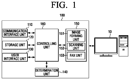
FIG. 1 is a block diagram showing a configuration of a profile creation apparatus according to an embodiment.
FIG. 2 is a flowchart showing an overall processing procedure according to an embodiment.
FIG. 3 is a diagram showing a weight designation UI image.
FIG. 4 is a diagram showing an example of a medium table MTB.
FIG. 5 is a diagram showing an example of a setting table STB.
FIG. 6 is a flowchart showing a base LUT creation processing procedure according to an embodiment.
FIGS. 7A to 7C are explanatory diagrams showing processing contents when a base 3D-LUT is created by Steps S100 to S300 in FIG. 6.
FIGS. 8A to 8C are explanatory diagrams showing correspondence relationships between hue values in an RGB color system as an input color system and hue values in a Lab color system.
FIGS. 9A to 9C are explanatory diagrams showing processing contents when a base 4D-LUT is created by Steps S100 to S300 in FIG. 6.
FIGS. 10A and 10B are explanatory diagram showing a creation method of a color correction LUT with the use of a base LUT.
FIG. 11 is an explanatory diagram showing a dynamic model used in smoothing processing according to an embodiment.
FIG. 12 is a diagram showing a state in which lattice points corresponding to gray axis lattice points are restricted by a gray target.
FIG. 13 is a flowchart showing typical processing procedure for smoothing processing.
FIG. 14 is a flowchart showing a detailed procedure of Step T100 in FIG. 13.
FIGS. 15A to 15D are explanatory diagram showing processing contents of Steps T120 to T150 in FIG. 13.
FIG. 16 is a flowchart showing a detailed procedure of optimization processing (Step T130 in FIG. 13).
FIG. 17 is a block diagram showing a configuration of a printer according to an embodiment of the invention.
FIG. 18 is a block diagram showing a software configuration of a printer.
FIG. 19 is a diagram showing a medium feature designation UI image.
FIG. 20 is a diagram showing an example of a color patch for automatically inputting a duty limit value.
FIGS. 21A and 21B are diagrams showing another example of a state in which a first luminosity feature and a second luminosity feature are normalized.
FIGS. 22A and 22B are diagrams showing an example of a state in which a first chromaticity feature and a second chromaticity feature are normalized.
FIGS. 23A and 23B are diagrams showing an example of a state in which a first luminosity feature and a second luminosity feature are approximated.
FIGS. 24A and 24B are diagrams showing an example of a state in which a first chromaticity feature and a second chromaticity feature are approximated.
FIGS. 25A and 25B are diagrams showing an example of a state in which an ink amount range is normalized.
FIG. 26 is a graph in which diverting medium tone and diverted medium tone are plotted on an a*b* plane.
FIG. 27 is a diagram showing a gray target when a diverting medium LUT is created.
FIG. 28 is a diagram showing an example of a state in which ink amounts are reduced.
FIG. 29 is a diagram showing a medium feature designation UI image according to a modified example.
Description of exemplary embodiments
Next, description will be given of an embodiment of the invention in the following order.
A. Apparatus configuration and overall processing procedure
B. Basic medium LUT creation procedure
B-1. Overall procedure
B-2. Dynamic model
B-3. Processing procedure for smoothing processing (smoothing and optimization processing)
B-4. Content of optimization processing
C. Configuration of printing apparatus
D. Diverting media LUT creation procedure
E. Modified Example
A. Apparatus Configuration and Overall Processing Procedure
FIG. 1 is a block diagram showing a configuration of a profile creation apparatus according to an embodiment of the invention. The profile creation apparatus is a subject which executes a profile creation method. Main parts of the apparatus are substantially realized by a computer 10.
Specifically, a CPU 12 provided in the computer 10 realizes each of the functions such as a base LUT creation module 100, a color correction LUT creation module 200, an LUT creation condition setting module 700, and the like by a reading a program (a profile creation program or the like) stored on a hard disk drive (HDD) 400 or the like and executing computation based on the program while developing the program on a RAM 13.
A display apparatus (a liquid crystal display, for example) which is not shown in the drawing is connected to the computer 10 and performs UI (user interface) display necessary for each processing. Moreover, an input apparatus (a keyboard and a mouse, for example) which is not shown in the drawing is connected to the computer 10, and information necessary for each processing is input via the input apparatus. In addition, a printer 20 (FIG. 17) and a colorimeter which is not shown in the drawing are connected to the computer 10.
Moreover, the computer 10 is provided with a forward model converter 300. The forward model converter 300 is further provided with a spectral printing model converter 310 and a color calculation unit 320. The forward model converter 300 corresponds to a color prediction model. Functions of each part will be described later. The term "LUT" is an abbreviation of look-up table as a kind of profile.
The base LUT creation module 100 includes an initial value setting module 120, a smoothing processing module 130, and a table creation module 140. The smoothing processing module 130 includes a color point displacement module 132, an ink amount optimization module 134, and an image quality evaluation index converter 136.
The LUT creation condition setting module 700 is provided with an ink amount converter 710, a UI module 720, and a setting information storage module 730.
The setting information storage module 730 manages a medium table MTB and a setting table STB stored on the HDD 400.
The functions of each part will be described later.
The HDD 400 is a storage apparatus for storing an inverse model initial LUT 410, a base 3D-LUT 510, a base 4D-LUT 520, a color correction 3D-LUT 610, a color correction 4D-LUT 620, and the like. However, LUTs other than the inverse model initial LUT 410 are created by the base LUT creation module 100 or the color correction LUT creation module 200. The base 3D-LUT 510 is a color conversion look-up table in which an RGB color system is an input and an ink amount is an output. The base 4D-LUT 520 is a color conversion look-up table in which a CMYK color system is an input and an ink amount is an output. In addition, "3D" and "4D" represent the number of input values.
The RGB color system and the CMYK color system as input color systems of the base LUTs 510 and 520 are not so-called device-dependent color systems but virtual color systems (or abstract color systems) not set in relation to a specific device. The base LUTs 510 and 520 are used for creating color correction LUTs 610 and 620, for example. The "base LUT" is named because the look-up table is used as a base for creating a color correction LUT. In addition, the "base LUT" corresponds to a "profile" created by the profile creation method according to an embodiment of the invention.
The color correction LUTs 610 and 620 are look-up tables for converting standard device-dependent color systems (an sRGB color system, a JAPAN COLOR 2001 color system, for example) into an ink amount of a specific printer.
Description will be given later of the inverse model initial LUT 410.
In this embodiment, an LUT for a printer capable of using four kinds of ink including cyan (C), magenta (M), yellow (Y), and black (K) is created. Although the four kinds of ink are assumed in this embodiment for simplicity of explanation, it is also possible to apply an embodiment of the invention to a case in which an LUT for other kinds of ink is created.
FIG. 2 is a flowchart showing an overall processing procedure according to this embodiment, which is executed by the computer 10. In Step S01, UI module 720 of the LUT creation condition setting module 700 receives designation of a medium, for which it is desired to create an LUT, via the display apparatus and the input apparatus. The UI module 720 displays a list of each medium and causes the display apparatus to display a medium selection UI image from which a user is allowed to select a desired medium. For example, the user can select a basic gloss paper, a basic matte paper, a basic normal paper, a basic proof paper, or the like as a basic medium. The term "basic medium" means a printing medium provided by a printer manufacturer, for example, and particularly printing media for which the forward model converter 300 (spectral printing model converter 310) and the image quality evaluation index converter 136 are prepared in advance in the embodiment of the invention. Features of the basic medium are known, and data specifying a color forming feature and a duty limit value when ink is made to adhere to each basic medium is stored in advance on the medium table MTB. The basic gloss paper, the basic matte paper, the basic normal paper, and the basic proof paper respectively belongs to a gloss paper group, a matte paper group, a normal paper group, and a proof group.
On the other hand, in the medium selection UI image, it is possible to select a gloss paper group sheet, a matte paper group sheet, a normal paper group sheet, a proof group sheet, a non-classified sheet, or the like as a diverting medium according to an embodiment of the invention as well as a basic medium. The "diverting media" means printing media which is not the same as any of the basic media and particularly printing media for which the forward model converter 300 (spectral printing model converter 310) and the image quality evaluation index converter 136 are not prepared in advance in the embodiment of the invention. When the user recognizes a group of a medium for which an LUT is created, it is possible to select a medium of the group. When the user does not recognizes the group of the medium, or it is difficult to classify the medium, it is possible to select a non-classified sheet. In addition, another configuration is also applicable in which the user does not designate a medium and a group of a medium is automatically determined based on a color phase obtained by performing color measurement on the medium. If the medium as a target of LUT creation is designated, information specifying the medium is registered in the setting table STB (Step S02).
In Step S03, the LUT creation condition setting module 700 obtains a default weight w.sub.L*, w.sub.a* . . . corresponding to the designated medium with reference to the medium table MTB stored on the HDD 400. The medium groups include a gloss paper group, a matte paper group, a normal paper group, a proof group, and a non-classified group, and the default weight w.sub.L*, w.sub.a* . . . for each group is stored on the medium table MTB. In Step S04, the UI module 720 causes the display apparatus to display a weight designation UI image and causes the input apparatus to receive designation of weight w.sub.L*, w.sub.a* . . . .
FIG. 3 shows the weight designation UI image, and FIG. 4 shows an example of the medium table MTB. In the weight designation UI image, designation of weight w.sub.L*, w.sub.a* . . . (0 to 100%) for each term constituting an object function E which will be described later is received. As shown in the drawing, a slider bar is provided for each of the setting items including a feature of granularity, color constancy, running cost, gamut, and a gradation feature, and increased weight is set for individual items if individual pointers are made to slide to the right side. In addition, a center position of the slider bar corresponds to a center value (50%) of the weight w.sub.L*, w.sub.a* . . . . A relationship between a position of the pointer in the slider bar and each value of weight w.sub.L*, w.sub.a* . . . may be a relationship of monotonic increase and can be defined by various functions such as a linear function, quadratic function, and the like.
Specifically, if a pointer for the feature of granularity in the weight designation UI image is made to slide to the further right side, an increased value of weight w.sub.GI is set. If a pointer for the color constancy is made to slide to the further right side, an increased value of weight w.sub.CII(A) . . . w.sub.CII(F12) is set. In this embodiment, the value of weight w.sub.CII(A) . . . w.sub.CII(F12) is equally set. It is a matter of course that the value of weight w.sub.CII(A) . . . w.sub.CII(F12) may be differentiated depending on the importance of the light source. If a pointer for the running cost is made to slide to the further right side, an increased value of weight w.sub.TI is set. If a pointer for the gamut is made to slide to the further right side, an increased value of weight w.sub.GMI is set. If a pointer for the gradation feature is made to slide to the further right side, an increased value of w.sub.L*, w.sub.a*, w.sub.b* is set. In this embodiment, the value of weight w.sub.L*, w.sub.a*, w.sub.b* is equally set. In addition, another configuration is also applicable in which it is possible to set a different weight w.sub.L*, w.sub.a*, w.sub.b* for each of luminosity L* and chromaticity a*, b*. A position of a pointer and a value of weight w.sub.L*, w.sub.a* . . . may be in a relationship of monotonic increase and can be defined as various functions such as a linear function, quadratic function, and the like.
In Step S04, an initial position of each pointer when the slider bars are firstly displayed is a position corresponding to the default weight w.sub.L*, w.sub.a* . . . obtained from the medium table MTB in Step S03. As the default weight w.sub.L*, w.sub.a* . . . , a preferable value is set in advance for each group of the media in the medium table MTB. If an enter button in the weight designation UI image is clicked without changing the initial positions of the pointers by the user, the default weight w.sub.L*, w.sub.a* . . . obtained in Step S03 is set as it is.
Specifically, as shown in FIG. 4, for the normal paper group, the default weight w.sub.TI for the running cost is set to be greater than the center value, the default weight w.sub.GMI for the gamut is set to be smaller than the center value, and the others are set to the center values. For the matte paper group and the non-classified group, the default weight w.sub.L*, w.sub.a* . . . for all items are set to the center values. For the gloss paper group, the weight w.sub.GI, the weight w.sub.L*, w.sub.a*, w.sub.b*, and the weight w.sub.GMI for the feature of granularity, the gradation feature, and the gamut are set to be greater than the center values, and the others are set to the center values. For the proof paper group, only the weight w.sub.GMI for gamut is set to be greater than the center value, and the others are set to the center values.
Since the default weight w.sub.L*, w.sub.a* . . . is set to a preferable value in consideration of a use purpose of the medium of each group, it is not basically necessary to change. When the user particularly intends to change the weight, it is possible to set desired weight w.sub.L*, w.sub.a* . . . by sliding the pointers from initial positions to desired positions. In addition, as for each weight w.sub.L*, w.sub.a* . . . , a relative size difference has meaning, and uniform increase or decrease as a whole does not have much meaning. Accordingly, a configuration is also applicable in which when a pointer for a certain item is displaced, pointers for the other items are uniformly displaced in the opposite direction.
In Step S05, the setting information storage module 730 registers in the setting table STB the weight w.sub.L*, w.sub.a* . . . corresponding to the position of each pointer when the enter button in the weight designation UI image is clicked.
In Step S06, it is determined whether or not the medium designated in Step S01 is a basic medium, and a duty limit value for the basic medium is obtained with reference to the medium table MTB in the case of the basic medium (Step S07). In this embodiment, the four kinds of CMYK ink are discriminated by subscript j (j=1 to 4) of a natural number, and individual ink amounts I.sub.1 to I.sub.4 to adhere to the medium are represented by vectors I=(I.sub.1, I.sub.2, I.sub.3, I.sub.4). The ink amount I.sub.j (including I.sub.j(R, G, B), .DELTA.I.sub.j, I.sub.jr, and h.sub.j which will be described later) represented with no subscript j means a matrix (vector) including ink amount I.sub.j of each ink as each. Moreover, the subscript j (j=5 to 7) represents an ink amount of a secondary color when two kinds among three kinds of CMY ink are mixed. That is, it is assumed that I.sub.5=I.sub.1+I.sub.2, I.sub.6=I.sub.1+I.sub.3, I.sub.7=I.sub.2+I.sub.3. The ink amounts I.sub.5 to I.sub.7 respectively reproduces colors corresponding to color phases of blue (B), red (R), and green (G) on the medium. Furthermore, the subscript j (j=8) represents an ink amount when all the four kinds of CMYK ink are mixed. That is, it is assumed that I.sub.8=I.sub.2+I.sub.2+I.sub.3+I.sub.4.
In this embodiment, the ink amount I.sub.j of each ink is expressed by 8 bits. As shown in FIG. 4, the duty limit value D.sub.Ij is stored for each individual ink (primary color), the total of the ink as a secondary color, and the total of all the ink. The duty limit value D.sub.Ij means a maximum ink amount which can adhere to a unit area with respect to each basic medium, and a lower limitation value at which ink bleeding occurs, for example, is set. Physical properties of ink droplets on the medium are different depending on the combinations of the ink and the media, and duty limit values D.sub.Ij which are different depending on the combinations are set. In addition, since a physical property which is different from that in an individual ink is exhibited even in a case in which a plurality of kinds of ink are mixed, the duty limit values D.sub.Ij (j=1 to 8) are set not only for the primary color but also for the secondary color (mixed color of two kinds of ink) and the total of all the ink. If the duty limit value D.sub.Ij can be obtained for the basic medium, the setting information storage module 730 causes the setting table STB to store the obtained duty limit value D.sub.Ij in Step S08. Moreover, in Step S08, the setting table STB is made to store an invalid flag indicating that the ink amount converter 710 is invalid. In this specification, it is assumed that a range of the subscript j in the case of a simple description of an ink amount I.sub.j is from 1 to 4 and a range of the subscript j in the case of a description of the duty limit value D.sub.Ij is from 1 to 8.
FIG. 5 shows an example of the setting table STB. When a basic medium is designated, a kind of aforementioned designated medium, weight w.sub.L*, w.sub.a* . . . , a duty limit value D.sub.Ij, an invalid flag, and a tone of a gray target (a.sub.gt*, b.sub.gt*) are stored in the setting table STB. In the case of a basic medium, the tone of the gray target (a.sub.gt*, b.sub.gt*) is set to (0, 0). On the other hand, when a diverting medium is designated, processing (from Step S09) which is different from that described above is executed. However, description will be firstly completed of the processing for creating an LUT when the basic medium is designated.
B. Basic Medium LUT Creation Procedure
B-1. Overall Procedure
FIG. 6 is a flowchart showing a procedure for creating a basic medium base LUT by the computer 10 according to the embodiment. FIGS. 7 A to 7C are explanatory diagrams showing processing contents when a base 3D-LUT is created by Steps S100 to S300 in FIG. 6. In Step S100, the forward model converter 300, the inverse model initial LUT 410, and the image quality evaluation index converter 136 are prepared (activated) based on information stored on the setting table STB. As described above, since the spectral printing model converter 310 and the image quality evaluation index converter 136 for the basic medium are prepared in advance for the basic media, the spectral printing model converter 310 and the image quality evaluation index converter 136 are activated and brought into available states. In addition, since the invalid flag is added to the setting table STB, the ink amount converter 710 is not activated.
Here, the "forward model" means a conversion model which predicts a color measurement value from an ink amount. That is, the forward model converter converts an ink amount I.sub.j into a hue value of a device-independent color system. On the other hand, the "inverse model" means a conversion model which predicts an ink amount from a color measurement value. That is, the inverse model converter converts a hue value of a device-independent color system into an ink amount. In this embodiment, a CIE-Lab color system will be employed and described as a device-independent color system. Hereinafter, a hue value of the CIE-Lab color system will be simply referred to as an "L*a*b* value" or an "Lab value".
As shown in FIG. 7A, the spectral printing model converter 310 constituting a former stage of the forward model converter 300 converts ink amounts I.sub.j of a plurality of kinds of ink into spectral reflectivity R(.lamda.) of color patches to be formed when printing is performed on a corresponding basic media. In this embodiment, the spectral printing model converter 310 set the ink amounts I.sub.j of the above-described four kinds of ink as input. In addition, the term "color patch" means a chromatic patch when narrowly used while the "color patch" in this specification is widely used to indicate a color patch including an achromatic patch as well. In addition, "print" indicates that ink is made to adhere to a medium in accordance with ink amounts.
The color calculation unit 320 calculates the hue values of the Lab color system from the spectral reflectivity R(.lamda.) calculated by the spectral printing model converter 310. In the calculation of the hue values, a light source (for example, a standard light D50) selected in advance is used as an observation condition of the color patch. In addition, as a method of creating the spectral printing model converter 310, it is possible to employ known various techniques, and a method described in JP-T-2007-511175 can be employed, for example.
The inverse model initial LUT 410 is a look-up table in which the L*a*b* value is an input and the ink amount I.sub.j is output. The L*a*b* value as an input value of the inverse model initial LUT 410 is a representative value of each small cell. The ink amount I.sub.j as an output value reproduces one L*a*b* value in a cell.
A representative value of each small cell is determined as follows, for example. In the initial LUT 410, an L*a*b* space is firstly divided into a plurality of small cells, and an optimal ink amount I.sub.j is selected and registered for each small cell. The selection of the optimal ink amount I.sub.j is made in consideration of an image quality of the color patch printed on the basic medium with the ink amount I.sub.j, for example. In general, there are multiple combinations of ink amounts I.sub.j for reproducing a certain L*a*b* value. However, selection of an optimal ink amount from a desired viewpoint such as an image quality or the like is registered in the initial LUT 410 from among the multiple combinations of the ink amounts I.sub.j for reproducing substantially the same L*a*b* values.
As a method of creating an initial LUT 410 by selecting an optimal ink amount for each small cell, it is possible to employ various known techniques, and a method described in JP-T-2007-511175 can be employed, for example. According to JP-T-2007-511175, the spectral printing model converter 310 and the inverse model initial LUT 410 are created by forming a color patch on a target print medium. That is, when the basic medium base LUT is created, the spectral printing model converter 310 and the inverse model initial LUT 410 created by forming a color patch on a basic medium are prepared.
In the initial LUT 410 prepared as described above, the L*a*b* value as an input value and the ink amount as an output value are not exactly in a correspondence relationship, and a value which is slightly different from the input value of the initial LUT 410 is obtained when the ink amount as an output value is converted into an L*a*b* value with the forward model converter 300. However, an initial LUT 410 in which an input value and an output value are completely in a correspondence relationship may be used.
In addition, it is also possible to create a base LUT without using the initial LUT 410. That is, it is possible to create the base LUT even if an LUT in which all ink amounts as output values are set to the same value is used instead of the initial LUT in which optimal ink amounts are set as described above, for example.
The description continues in the full USPTO document.
 Lapsed, fee not paid8 drawings