Lapsed, fee not paid25 drawings
Hardware & Electronics · US 8,674,461 B2
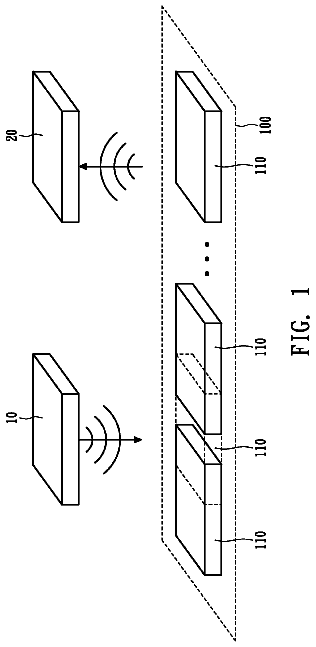
Hybrid plasma-semiconductor electronic and optical devices
The invention provides combination semiconductor and plasma devices, including transistors and phototransistors.
US 8,674,544 B2 · Assignee: Geneva Cleantech, Inc. · Inventors: Rada; Patrick A. et al.
Sheet 1 of 22 from the published document. All sheets in the USPTO PDF
Methods and apparatus for power factor correction include selectively coupling bit reactive loads with a load having dynamic reactive properties to dynamically correct a power factor. Methods and apparatus for reducing distortion in a power delivery system include a means for determining distortion in a power line, forming a corrective signal according to the distortion and selectively sinking and sourcing current to the power line according to the corrective signal. Furthermore, power for a solar power system is injected into a load via the same apparatus.
Power factor correction is an important component of increasing efficiency of modern day power delivery systems. Due to reactive components in the loads that consume power such as appliances that include a motor, a phase shift develops between a current and a voltage component of a power signal. The power factor of an AC electric power system is defined as the ratio of the real power flowing to the load to the apparent power and is a number between 0 and 1 (frequently expressed as a percentage, e.g. 0.5 pf=50% pf). Real power (P) is the capacity of the circuit for performing work in a particular time. Apparent power (S) is the product of the current and voltage of the circuit. The Reactive Power (Q) is defined as the square root of the difference of the squares of S and P. Where reactive loads are present, such as with capacitors or inductors, energy storage in the loads result in a time
1 of 22 drawing sheets so far from the published document, cropped to the drawing. Every sheet is in the USPTO PDF.
What the patent claimed, word for word. All of it is now free to use.
Independent claims stand on their own. The others add detail to the claim they name.
The present invention relates to the field of power electronics. More specifically, the present invention relates to reducing distortion and noise of power delivered to or generated by a load and improving power factor.
Power factor correction is an important component of increasing efficiency of modern day power delivery systems. Due to reactive components in the loads that consume power such as appliances that include a motor, a phase shift develops between a current and a voltage component of a power signal. The power factor of an AC electric power system is defined as the ratio of the real power flowing to the load to the apparent power and is a number between 0 and 1 (frequently expressed as a percentage, e.g. 0.5 pf=50% pf). Real power (P) is the capacity of the circuit for performing work in a particular time. Apparent power (S) is the product of the current and voltage of the circuit. The Reactive Power (Q) is defined as the square root of the difference of the squares of S and P. Where reactive loads are present, such as with capacitors or inductors, energy storage in the loads result in a time difference between the current and voltage waveforms. During each cycle of the AC voltage, extra energy, in addition to any energy consumed in the load, is temporarily stored in the load in electric or magnetic fields, and then returned to the power grid a fraction of a second later in the cycle. The "ebb and flow" of this nonproductive power increases the current in the line. Thus, a circuit with a low power factor will use higher currents to transfer a given quantity of real power than a circuit with a high power factor. A linear load does not change the shape of the waveform of the current, but may change the relative timing (phase) between voltage and current. Generally, methods and apparatus to correct power factor have involved coupling a fixed corrective load having a known reactive value to a power line. The fixed capacitive reactive load counteracts the reactive effect of inductive loads vice versa, improving the power factor of the line. However, a fixed reactive load is only able to correct the power factor of a power line by a fixed amount to a certain extent because the power factor may be dynamic due to the changing nature of loads that are coupled and decoupled to the power line. To that end, later developments included several fixed reactive loads that may be selectively coupled to a power line in order to correct power factor. However, such systems require monitoring by an operator who must continually monitor the power factor in order to couple and decouple fixed reactive loads in order to counteract the ever changing power factor of the power line.
The changing landscape of electronics has introduced other inefficiencies in the delivery of power. The increased use of personal electrical appliances has caused an increase in the use of wall mounted AC-DC converters to supply power to devices and recharge the batteries of everyday items such as laptops, cellular telephones, cameras, and the like. The ubiquity of such items has caused users to have several of these converters, known as "wall warts" to be coupled into power systems. The two most common AC-DC converters are known as linear converters and switched mode converters. Linear converters utilize a step down transformer to step down the standard 120V power available in US residences to a desired AC voltage. A bridge rectifier rectifies that voltage. The bridge rectifier is generally coupled to a capacitor. Generally, this capacitor is of a high value. The capacitor forms a counter electromotive force. The capacitor forms a near DC voltage as it is charged and discharged. However, as it is charged, the capacitor draws current only a fraction of the cycle by the non linear bridge rectifier. As a result, the current waveform does not match the voltage and contains a heavy harmonic distortion component. Total harmonic distortion (THD) is the sum of the powers of all harmonic components to the power of the fundamental frequency. This harmonic distortion may be reflected back into the power network.
A switching power supply works on a different principle but also injects harmonics into a power delivery network. In general, a switched mode power supply operates by rectifying the 120V voltage available in US residences. The rectification against a counter electro motive force, such as a big reservoir capacitor, again adds harmonics and distortion. Also, the widespread adaptation of various types of linear or switch mode integrated circuits cause the system to create electrical noise. Furthermore, reactive components in the alternating current network degrades power factor, and integrated circuits cause harmonics and noise to be reflected into the power line. These harmonics manifest as harmonic distortion in the current component of a power signal. Because the power network has a nonzero impedance, distortion along the current component may also translate to amplitude distortion. Amplitude distortion is distortion occurring in a system, subsystem, or device when the output amplitude is not a linear function of the input amplitude under specified conditions. Other undesirable effects are also formed, such as power factor distortion and overall reduction of energy transfer. Such effects decrease efficiency and reduce quality in the delivery of power. To that end, what is needed are methods and apparatus capable of not only correcting a power factor in a power delivery network, but also reducing or eliminating distortion in a power line, thereby allowing for maximum efficiency and quality in power delivery. As a result, overall energy consumption may be reduced.
The invention provided herein allows for increasing efficiency and quality of power delivery over a power network to a load. The person of ordinary skill having the benefit of this disclosure will appreciate that the methods and apparatus discussed herein may be applied to a great variety of loads having reactive and non linear components that cause a less than perfect power factor and cause distortion and noise and the like to be injected back into the power network. In some applications, the load is a family residence. The load is a parallel combination of all appliances drawing power within the residence. To the grid, through a power meter, the residence appears to be one dynamic load having changing reactive and non linear properties as users within the residence activate and deactivate appliances. Advantageously, the invention provided herein overcomes prior art solutions inherent drawbacks such as prohibitive cost, complicated installation at multiple locations, fixed PF compensation that may over or under compensate and reduce PF, and poor performance. The invention provided herein is able to correct a power factor to a load by dynamically measuring a reactive power component of the load, and coupling at least one corrective reactive load. As the reactive power changes, such as when a washing machine is activated, the invention is able to recognize that the characteristic of the load has changed, and is able to couple or decouple other corrective reactive loads to the load causing the poor power factor. Furthermore, the invention provided herein is able to correct distortion, noise, and the like in the power delivered by a network to a load, thereby improving the quality of the power. The invention provides for comparing an electrical signal having distortion, noise, or the like to a reference signal. The electrical signal may be the current component of the power delivered to a load through a network. The reference signal may be derived from a voltage component of the power delivered to a load, or be synthesized separately but synchronized with the voltage waveform. A corrective signal is derived by comparing, or subtracting, the reference signal from the signal having distortion. The corrective signal comprises the distortion. Current is sunk or sourced from the signal having distortion according to the corrective signal, resulting in reduced distortion. Advantageously, the invention is able to correct distortion caused by all non linear loads in a residence at one point. The invention is able to be coupled between a utility meter and the residence. As a result, the invention is agnostic to the number of appliances in the residence, their location, or any other parameter. Also, the invention is energy efficient since it improves distortion and PF as necessary without increasing PF or distortion and without the addition of any other electrical load within the property network.
In one aspect of the invention, a method of reducing distortion in an electrical signal having distortion comprises sensing a distortion in the electrical signal having distortion and combining a factor of the distortion with the electrical signal having distortion. In some embodiments, the sensing step comprises comparing the electrical signal having distortion to a reference signal to obtain a difference signal and scaling the difference signal to form the factor of the distortion. The combining step comprises subtracting the factor of the distortion from the electrical signal having distortion if the factor of the distortion is positive and adding the factor of the distortion to the electrical signal having distortion if the factor of the distortion is negative. In some embodiments, the subtracting step comprises applying the factor of the distortion to a first controlled current source coupled to the electrical signal having distortion and the adding step comprises applying the factor of the distortion to a second controlled current source coupled to the electrical signal having distortion. Applying the factor of the distortion to a first controlled current source further comprises applying a power factor corrected positive power signal to the first controlled current source and applying the factor of the distortion to a second controlled current source further comprises applying a power factor corrected negative power signal to the second controlled current source.
In some embodiments, the combining step comprises modulating the factor of the distortion. The factor of the distortion is then added to the electrical signal having distortion if the factor of the distortion is negative and subtracting the factor of the distortion from the electrical signal having Distortion if the factor of the distortion is positive. The adding and subtracting step are able to be achieved by applying the factor of the distortion to a first switch coupled to the electrical signal having Distortion and applying the factor of the distortion to a second switch coupled to the electrical signal having Distortion. Modulating the factor of distortion can include pulse width modulation, delta-sigma modulation, pulse code modulation, pulse density modulation, or pulse position modulation. Applying the factor of the distortion to a first switch includes applying a power factor corrected positive power signal to the first switch and applying the factor of the distortion to a second switch includes applying a power factor corrected negative power signal to the second switch. Advantageously, the use of modulation techniques allows for highly efficient control of the switches. In some embodiments, analog or digital filters may be included for filtering away the modulating signal.
In some applications, an impedance of the power network may be far lower than the impedance of the load that the power network is delivering power to. In such circumstances, it will be appreciated by persons having the benefit of this disclosure that the direction of sourcing or sinking current may need to be reversed. By way of example, a negative distortion is regularly corrected by injecting or sourcing current into the power line. However, if the impedance of the load is greater than the impedance of the network, the current will be injected into the network rather than the load. As a result, the opposite function may be done. This leads to adequate distortion correction of the total current waveform drawn from the grid.
In another aspect of the invention, a method for reducing distortion in a power line comprises correcting a power factor in the power line such that the power factor is substantially one, comparing a current portion of the power line to a desired reference signal, thereby forming a corrective signal, and selectively sinking and sourcing current to the power line according to the corrective signal. Correcting a power factor comprises any known method of power factor correction or any method described herein. In some embodiments, selectively sinking or sourcing current comprises applying the corrective signal to at least one controlled current source, wherein the controlled current source couples a current supply with the power line according to the corrective signal. Alternatively, selectively sinking or sourcing current comprises modulating the corrective signal and applying the modulated corrective signal to at least one switch, wherein the switch couples a current supply with the power line and filtering modulation noise. Modulating the corrective signal comprises any among pulse width modulation, delta-sigma modulation, pulse code modulation, pulse density modulation, or pulse position modulation.
In some applications, an impedance of the power network may be far lower than the impedance of the load that the power network is delivering power to. In such circumstances, it will be appreciated by persons having the benefit of this disclosure that the direction of sourcing or sinking current may need to be reversed. By way of example, a negative distortion is regularly corrected by injecting or sourcing current into the power line. However, if the impedance of the load is greater than the impedance of the network, the current will be injected into the network rather than the load. As a result, the opposite function may be done. This leads to adequate distortion correction of the total current waveform drawn from the grid.
In operation, distortion in electrical signals, such as the power being delivered to a residence, is reduced. The distortion may be harmonic distortion, amplitude distortion, noise, elevated spectral noise, or the like. The power being delivered to a residence comprises a voltage and a current. Generally, the current component of the power delivered to a load will display distortion due to non linearities in the load. The distortion is able to be ascertained by comparing the current to a perfect sine wave, such as the voltage component of the power. This perfect sine wave is able to function as a reference signal. In cases where the voltage sinewave is less than perfect, such as when amplitude distortion has distorted the voltage sinewave, a near perfect sinewave is able to be created locally by synchronizing with the voltage sinewave. For example, zero crossing transitions may be utilized as markers to form a near perfect sinewave. By subtracting the reference signal from the signal having distortion, a corrective signal is formed. The corrective signal comprises a factor of the distortion. A positive portion of the distortion is applied to a current sink coupled to the lines delivering power to the residence. The current sink sinks current out of the line according to the distortion. Similarly, a negative portion of the distortion is applied to a current source that is also coupled to the lines delivering power to the residence. When the distortion is negative, the current source sources current into the line according to the distortion. As a result, the distortion is removed from the current being drawn from the grid.
In some embodiments, the corrective signal may be modulated in order to enhance efficiency. Methods such as pulse width modulation, delta-sigma modulation, pulse code modulation, pulse density modulation, or pulse position modulation. The modulated corrective signal is applied to an active switch, such as a MOSFET, that conducts current into or away from the line providing power to the house according to the distortion.
In some embodiments, the method of reducing distortion further comprises correcting a power factor. A method of dynamic power factor correction comprises determining the reactive power of the first load, determining a power factor resulting from that reactive power, determining an optimum corrective reactive load to be coupled to the first load to bring the ratio to substantially one and coupling the optimum corrective reactive load to the first load.
In some embodiments, coupling the optimum reactive load to the first load includes selecting a quantization level for a desired accuracy, the quantization level having an MSB and an LSB, determining an MSB reactive load determining an LSB reactive load, and closing switches associated with any bit required to achieve the desired accuracy, wherein the switches electrically couple any among the MSB reactive load and LSB reactive load to the first load. Generally, the desired accuracy comprises determining an acceptable value for the ratio. The quantization level is able to further comprise at least one bit between the MSB and LSB. Determining a value for the LSB reactive load, MSB reactive load, and a bit reactive load of the at least one bit includes determining a maximum reactive component of the first load. The MSB reactive load, LSB reactive load, and bit reactive load of the at least one bit is generally, a capacitor and may be coupled to the reactive load via any among a switch, an active switch, a MOSFET, an IGBT transistor, a pair of MOSFETs, a pair of IGBT transistors, a TRIAC, a relay, a thyristor, and a pair of thyristors. In some embodiments, the reactive power is continually monitored and a new optimum corrective reactive load to be coupled to the first load to bring the reactive power to substantially zero, and the power factor to substantially one, is dynamically determined.
In another aspect of the invention, a system for reducing distortion in an electrical signal having distortion comprises a power factor correcting module for bringing a power factor in the signal having distortion to substantially one, a substracter for comparing a current portion of the power line to a desired reference signal, thereby forming a corrective signal, and an electric circuit for selectively sinking and sourcing current to the power line according to the corrective signal. The power factor correcting module comprises a sensor for measuring the reactive power of a first load coupled to power line and a plurality of bit reactive loads for coupling with the first load to counteract a reactive component of the first load. In some embodiments, the electric circuit for selectively sinking or sourcing current is configured to apply the corrective signal to at least one controlled current source, wherein the controlled current source couples a current supply with the power line according to the corrective signal. Alternatively, the electric circuit for selectively sinking or sourcing current comprises a modulator for modulating the corrective signal and applying the modulated corrective signal to at least one switch, wherein the switch couples a current supply with the power line and a filter for filtering modulation noise. The modulator comprises any among a pulse width modulator, delta-sigma modulator, pulse code modulator, pulse density modulator, or pulse position modulator.
In operation, an electrical circuit for reducing distortion in a current signal having distortion comprises a first input for receiving the current signal having distortion, a second input for receiving a reference signal, a substracter coupled to the first input and second input for subtracting the current signal having distortion from the reference signal thereby forming a first corrective signal, and a circuit for selectively combining a positive portion of the first corrective signal and a negative portion of the first corrective signal with the current signal having distortion. The substracter is able to be an analog circuit, such as an operational amplifier configured to subtract one input from another. Alternatively, the substracter may be a digital system, such as a A/D converter capable of digitally subtracting one converted bitstream input from another, and a D/A converter for converting the result to an analog signal comprising the corrective signal.
In some embodiments, the circuit for selectively combining is able to be a positive rectifier coupled to an output of the substracter for determining the positive portion of the corrective signal and a first controlled current source, and a negative rectifier coupled to an output of the substracter for determining the negative portion corrective signal and a second controlled current source. Both controlled current sources are coupled to a positive power supply and a negative power supply respectively in order to selectively sink or source current to or from a main power line in order to correct distortion. In operation, when the distortion is negative, current is sourced to a power supply line according to the negative distortion to compensate. Likewise, when the distortion is positive, current is sunk away according to the positive distortion, thereby compensating.
Alternatively, the circuit for selectively combining is able to be a positive trigger comparator coupled to an output of the substracter for determining a positive portion of the corrective signal, a negative trigger comparator coupled to the output of the substracter for determining a negative portion of the corrective signal and a modulator. The modulator is able to be any useful type of modulator, including a pulse width modulator, a delta-sigma modulator, a pulse code modulator, a pulse density modulator, or a pulse position modulator. The modulator is able to be coupled to an output of the positive trigger comparator and an output of the negative trigger comparator for modulating any among the positive portion of the corrective signal and the negative portion of the corrective signal. In some embodiments, a first switch is coupled to positive trigger comparator. The first switch is able to selectively couple current from a negative DC power supply according to the positive portion of the corrective signal, thereby reducing distortion. Likewise, the second switch is able to selectively couple current from a positive DC power supply according to the positive portion of the corrective signal, thereby reducing distortion.
In some applications, an impedance of the power network may be far lower than the impedance of the load that the power network is delivering power to. In such circumstances, it will be appreciated by persons having the benefit of this disclosure that the direction of sourcing or sinking current may need to be reversed. By way of example, a negative distortion is regularly corrected by injecting or sourcing current into the power line. However, if the impedance of the load is greater than the impedance of the network, the current will be injected into the network rather than the load. As a result, the opposite function may be done. By sinking current from the power line, current is injected in the opposite direction.
In some embodiments, the electrical circuit for reducing distortion further comprises a power factor correction circuit for bringing the power factor between the current and the voltage being delivered to substantially unity. A system for power factor correction comprises means for determining the reactive power of a load, means for determining an optimum corrective reactive load to be coupled to the first load to bring the power factor to substantially one and the reactive power to substantially zero, and means for coupling the optimum reactive load to the first load. In some embodiments, the means for coupling the optimum reactive load to the first load comprises means for selecting a quantization level for a desired accuracy, the quantization level having an MSB and an LSB, means for determining an MSB reactive load, means for determining an LSB reactive load, and means for closing switches associated with any bit required to achieve the desired accuracy, wherein the switches electrically couple any among the MSB reactive load and LSB reactive load to the first load. The quantization level further comprises at least one bit between the MSB and LSB. More bits between the MSB and LSB will result in greater accuracy of power factor correction, or a power factor substantially closer to one. The bit reactive loads are generally a capacitor, and may be coupled to the reactive load via a switch, an active switch, MOSFET, an IGBT transistor, a pair of MOSFETs, a pair of IGBT transistors, a TRIAC, a relay, a thyristor, and a pair of thyristors.
In another embodiment of the invention, a system for reducing distortion in an electrical signal having distortion comprises an electric circuit for comparing at least a portion of the electrical signal having distortion in a power line to a desired reference signal, thereby forming a corrective signal; and an electric circuit for selectively sinking and sourcing current from one of a DC rectifier and a solar panel to the electrical signal having distortion according to the corrective signal to correct the distortion; and selectively injecting additive current from the solar panel into at least one of a load or a power grid. Preferably, the system further comprises a processor for determining when the solar power is generating current and a processor for switching between the DC rectifier and the solar panel for sinking and sourcing current, which may be the same processing unit. Also, the system comprises a transformer, the transforming having a primary winding and a secondary winding, for galvanically isolating the electric circuit for selectively sinking and sourcing from the power line, wherein the secondary may be coupled in series or in parallel. Preferably, the electric circuit for selectively sinking or sourcing current comprises a positive DC power supply selectively coupled to one of the DC rectifier and the solar panel or providing a positive DC current, a negative DC power supply selectively coupled to one of the DC rectifier and the solar panel for providing a negative DC current, a processor for selectively sourcing current into the power line from one of the positive DC power supply in response to a negative distortion; or sinking current from the power line to the negative DC power supply in response to a positive distortion, which again can the same processor mentioned above.
Similarly, a method of correcting a harmonic distortion in a power line comprises generating a corrective signal as discussed above, generating positive DC current from one of a rectifier and a solar power system, generating a negative DC current by inverting the positive DC current, selectively sourcing the positive DC current into a load according to the corrective signal to correct a negative distortion, selectively sourcing the negative DC current into a load according to the corrective signal to correct a positive distortion, and injecting additional available power into at least one of the load and the power line from the solar power system, thereby increasing total current. Preferably, the method also comprises galvanically isolating the load from the positive DC power supply and negative DC power supply. In some embodiments, generating positive DC current from one of a rectifier and a solar power system comprises determining whether the solar power system is generating current, and sourcing current from the solar power system if the solar power system is generating, or sourcing current from the rectifier if the solar power system is not generating current. Advantageously, the method and apparatus mentioned allow for injection of current from a solar power system without the use of a costly and inefficient inverter, as will be explain in detail below.
In another aspect of the invention, a system for correcting harmonic distortion comprises means for determining the harmonic energy in a power line means for storing the harmonic energy, and means for selectively releasing the harmonic energy to counter harmonic energy of an opposite magnitude. Preferably, the means for determining the harmonic energy in a power line is as described above, including a sensor for measuring a current component in a power line, an oscillator for generating a reference signal, and a comparator for comparing the current component to the reference signal there by generating a corrective signal, wherein the corrective signal represents harmonic energy in the power line. The means for storing energy can be a capacitor or inductor. The energy is released by a switch, which selectively couples the means for storing harmonic energy between any among a positive power supply, a negative power supply, and a load. Preferably, the system further comprises a modulator to modulate the corrective signal to drive a transistor to selectively charge the means for storing energy.
Likewise, a method of correcting harmonic distortion in a signal having harmonic distortion comprises determining the harmonic energy in a power line, storing the harmonic energy, and selectively releasing the harmonic energy to counter harmonic energy of an opposite magnitude. The corrective signal is generated as described above, and the energy is stored and released as described above. As can be appreciated, using harmonic energy to correct future harmonic error saves from using an external power source to correct the energy, or drawing greater current from a power line.
In another embodiment, modulation of the power supplies is contemplated. Such an embodiment comprises means for comparing at least a portion of the electrical signal having distortion in a power line to a desired reference signal, thereby forming a corrective signal, means for selectively sinking and sourcing current to the electrical signal having distortion from a negative power supply and a positive power supply respectively, means for modulating the positive power supply according the corrective signal, and means for modulating the negative power supply according to the corrective signal. In analog electronics, such a power supply is referred to as a Class H amplifier. Class H amplifiers enjoy greater efficiency since the power supply closely tracks the current stage of an amplifier. In this implementation, the power supply tracks the corrective signal. Preferably, the means for comparing comprises a sensor for sensing the signal having distortion, an oscillator for generating a reference signal, and a comparator for comparing the signal having distortion to the reference signal thereby generating a corrective signal. The means for selectively sinking and sourcing current comprise a first transistor coupled to the positive power supply for sourcing current to correct a negative harmonic according to the corrective signal, and a second transistor coupled to the negative power supply for sinking current to correct a positive harmonic according to the corrective signal. The means for modulating the power supplies comprises a first transistor for receiving the corrective signal and an LC-flywheel network for deriving a positive and a negative average of the corrective signals respectively.
The corresponding method for the above embodiment comprises forming a corrective signal as previously discussed, selectively sinking and sourcing current to the electrical signal having distortion from a negative power supply and a positive power supply respectively, and modulating the power supplies according to the corrective signal.
Advantageously, the embodiments summarized above are able to be implemented on the scale of a family residence. The systems and circuits summarized above are able to be produced inexpensively, allowing average homeowners access to such devices. Prior art solutions generally include devices that are either targeted for industrial applications, and therefore are configured to correct power factor in networks of far greater current carrying capacity. As a result, they are very large and cost many thousands of dollars and are not amenable to residential applications. Other solutions merely correct power factor and must be applied to individual devices within a home. Furthermore, they are generally fixed capacitor power factor correction units that do not adequately correct a power factor, and may in some instances degrade power factor. Still other solutions are systems wherein a central control unit drives power factor and harmonic correction units that must be coupled to individual appliances, wherein each coupling is an installation step. Such systems also attempt to correct current waveforms by drawing and dissipating current in a purely resistive load, such as an individual appliance. Conversely, the systems and circuits and methods implemented therein are generally to be coupled between a main utility meter and the home, allowing for simple, one step installation.
FIG. 1 is a schematic block diagram of a power factor correction circuit per an embodiment of this invention.
FIG. 2 is a schematic block diagram of a power factor correction circuit per an embodiment of this invention.
FIG. 3A is a time vs. amplitude graph of a power factor corrected power signal having distortion.
FIG. 3B is a time vs. amplitude graph of a power factor corrected power signal having distortion.
FIG. 3C is a time vs. amplitude graph of a power factor corrected power signal having distortion.
FIG. 3D is a time vs. amplitude graph of a power signal having a poor power factor, distortion and methods of correction of distortion.
FIG. 4 is a schematic block diagram of a distortion reducing circuit per an embodiment of this invention.
FIG. 5 is a schematic block diagram of a distortion reducing circuit having modulation per an embodiment of this invention.
FIG. 6 is a schematic block diagram of a distortion reducing circuit having modulation per an embodiment of this invention.
FIG. 7 is a schematic block diagram of a distortion reducing circuit having modulation and enhanced filtering per an embodiment of this invention.
FIG. 8 is a schematic block diagram of a distortion reducing circuit having modulation and enhanced filtering per an embodiment of this invention.
FIG. 9 is an alternate schematic block diagram of a distortion reducing circuit having modulation and enhanced filtering per an embodiment of this invention.
FIG. 10 is a schematic block diagram of a distortion reducing circuit having modulation and enhanced filtering and galvanic isolation per an embodiment of this invention.
FIG. 11 is a schematic block diagram of a distortion reducing circuit having modulation and enhanced filtering and galvanic isolation coupled in series with a load, per an embodiment of this invention.
FIG. 12A is an example of a Class G power supply waveform.
FIG. 12B is an example of a Class H power supply waveform.
FIG. 12C is a schematic block diagram of a distortion reducing circuit having Class H power supplies.
FIG. 12D is an enhanced schematic block diagram of a distortion reducing circuit having Class H power supplies.
FIG. 13A is a schematic block diagram of a distortion reducing circuit having a solar power system.
FIG. 13B is a schematic block diagram of a prior art solar power system.
FIG. 13C is a graphical representation of current generated by a solar power system injected into a property load or AC power grid.
FIG. 14A is a schematic block diagram of a distortion reducing circuit having the ability to recycle harmonic energy and use it to correct later harmonic distortion.
FIG. 14B is a graphical representation of energy in a distorted current signal that can be recycled for later use to correct harmonic distortion.
FIG. 14C is a schematic block diagram of a distortion reducing circuit having the ability to recycle harmonic energy and use it to correct later harmonic distortion.
FIG. 14D is a schematic block diagram of a distortion reducing circuit having the ability to recycle harmonic energy and use it to correct later harmonic distortion.
In the following description, numerous details and alternatives are set forth for the purpose of explanation. However, one of ordinary skill in the art having the benefit of this disclosure will realize that the invention can be practiced without the use of these specific details. In other instances, well-known structures and devices are shown in block diagram form in order not to obscure the description of the invention with unnecessary detail.
Power Factor Correction Methods and Apparatus
FIG. 1 is a block schematic diagram of a power factor correction circuit (PFC) 100 per an aspect of the present invention. Power factor (PF) is defined as the ratio of the real power flowing to the load to the apparent power, and is a number between zero and one. It may also be expressed as a percentage, i.e. a PF of 0.5 is 50%. Real power is the capacity of the circuit for performing work in a particular time. Apparent power is the product of the current and voltage of the circuit. A load with a PF substantially closer to zero draws more current than a load with a PF closer to one for the same amount of useful power transferred. It is generally understood that a PF closer to zero is considered to be a low PF and a PF closer to one is considered to be a high PF. It is highly desirable to optimize the PF and bring it close to one especially when and if the utility energy meter records only the apparent power consumed over time and not the active power. In general, utility companies prefer to have a good power factor in a grid network in order to optimize the infrastructure and maximize the active energy it can deliver to its customers. Bad power factor such as 0.9 and lower, will generate excessive apparent current loss in the lines and stress the grid due to higher currents.
The description continues in the full USPTO document.
About 6,143 words. The USPTO PDF has it with every drawing.
Fees are due 3.5, 7.5 and 11.5 years after grant. This patent expired on March 18, 2026, so the fee marked "not paid" was the one that went unpaid.
METHODS AND APPARATUS FOR POWER FACTOR CORRECTION AND REDUCTION OF DISTORTION IN AND NOISE IN A POWER SUPPLY DELIVERY NETWORK
Filed Jan 2011 · published Jun 2011Methods and apparatus for power factor correction and reduction of distortion in and noise in a power supply delivery network
Filed Jan 2011 · granted Mar 2014Earlier publications, parents and continuations. None of them can still be enforced, or this patent would not be listed.
Prior art cited by the examiner or applicant. Useful when you check your own idea for novelty.
Everything on this page comes from the documents linked above.