Background
1. Field of invention
Generally, the present invention relates to wireless communication among functional modules of an integrated circuit, and specifically, to integrating a waveguide with the functional modules to wirelessly communicate using a multiple access transmission scheme.
2. Related art
A semiconductor device fabrication operation is commonly used to manufacture integrated circuits onto a semiconductor substrate to form a semiconductor wafer. Integrated circuits from among various semiconductor wafers are often packaged together to form an electronic device, such as a mobile device or a personal computing device to provide some examples. These integrated circuits are often interconnected to each other using conductive wires and/or traces and communicate among themselves using these conductive wires and/or traces.
Typically, the conductive wires and/or traces are suitable for communication among the integrated circuits when low data rates and/or low frequencies are used to communicate over relatively short distances. However, as the data rates, the frequencies, and/or the distances increase, physical properties of the conductive wires and/or traces may degrade communication among the integrated circuits. For example, an undesirable or a parasitic capacitance and/or inductance of the conductive wires and/or traces may degrade communication among the integrated circuits at these increased data rates, frequencies, and/or distances.
Electronic designers are creating new electronic devices that include more integrated circuits that communicate at increased data rates and/or frequencies and over longer distances thereby making the use of conductive wires and/or traces for communication problematic. Thus, there is a need for interconnecting integrated circuits over longer distances at increased data rates and/or frequencies that overcomes the shortcomings described above. Further aspects and advantages of the present invention will become apparent from the Detailed Description that follows.
Brief description of the drawings/figures
Embodiments of the invention are described with reference to the accompanying drawings. In the drawings, like reference numbers indicate identical or functionally similar elements. Additionally, the left most digit(s) of a reference number identifies the drawing in which the reference number first appears.
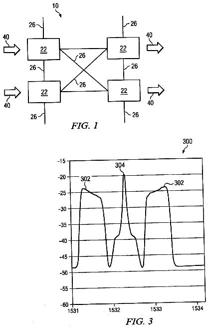
FIG. 1 illustrates a schematic block diagram of a semiconductor wafer according to an exemplary embodiment of the present invention;
FIG. 2 illustrates a first block diagram of an integrated circuit that is formed onto a semiconductor substrate according to an exemplary embodiment of the present invention;
FIG. 3 illustrates a second block diagram of the integrated circuit that is formed onto the semiconductor wafer according to an exemplary embodiment of the present invention;
FIG. 4 illustrates a block diagram of a functional module that may be implemented as part of the integrated circuit according to an exemplary embodiment of the present invention;
FIG. 5 illustrates a first exemplary configuration and arrangement of the integrated circuit according to an exemplary embodiment of the present invention;
FIG. 6 illustrates a first integrated waveguide that is implemented as part of the first exemplary configuration and arrangement of the integrated circuit according to an exemplary embodiment of the present invention;
FIG. 7 illustrates a first conductive element that may be used in the integrated waveguide according to an exemplary embodiment of the present invention;
FIG. 8 illustrates a second conductive element that may be used in the first integrated waveguide according to an exemplary embodiment of the present invention;
FIG. 9 illustrates a transmit mode of operation of the first integrated waveguide according to an exemplary embodiment of the present invention;
FIG. 10 illustrates a receive mode of operation of the first integrated waveguide according to an exemplary embodiment of the present invention;
FIG. 11 illustrates a second exemplary configuration and arrangement of the integrated circuit according to an exemplary embodiment of the present invention;
FIG. 12 illustrates a second integrated waveguide that is implemented as part of the second exemplary configuration and arrangement of the integrated circuit according to an exemplary embodiment of the present invention;
FIG. 13A illustrates a first exemplary configuration of a first electro-mechanical device that may be used to dynamically configure operating characteristics of the second integrated waveguide according to an exemplary embodiment of the present invention;
FIG. 13B illustrates a second exemplary configuration of the first electro-mechanical device according to an exemplary embodiment of the present invention;
FIG. 14A illustrates a first exemplary configuration of a second electro-mechanical device that may be used to dynamically configure operating characteristics of the second integrated waveguide according to an exemplary embodiment of the present invention;
FIG. 14B illustrates a second exemplary configurations of the second electro-mechanical device according to an exemplary embodiment of the present invention;
FIG. 15 illustrates a flip chip configuration of functional modules of the integrated circuit according to an exemplary embodiment of the present invention;
FIG. 16 illustrates a flip chip configuration of an integrated waveguide that is implemented as part of the integrated circuit according to an exemplary embodiment of the present invention;
FIG. 17 illustrates a third exemplary configuration and arrangement of the integrated circuit according to an exemplary embodiment of the present invention;
FIG. 18 illustrates a fourth exemplary configuration and arrangement of the integrated circuit according to an exemplary embodiment of the present invention;
FIG. 19 illustrates a fifth exemplary configuration and arrangement of the integrated circuit according to an exemplary embodiment of the present invention;
FIG. 20 illustrates a first exemplary configuration and arrangement of one or more functional modules of the integrated circuit according to an exemplary embodiment of the present invention;
FIG. 21 illustrates a sixth exemplary configuration and arrangement of the integrated circuit according to an exemplary embodiment of the present invention;
FIG. 22 illustrates a second exemplary configuration and arrangement of one or more functional modules of the integrated circuit according to an exemplary embodiment of the present invention;
FIG. 23 illustrates a seventh exemplary configuration and arrangement of the integrated circuit according to an exemplary embodiment of the present invention;
FIG. 24 illustrates an exemplary Multichip Module (MCM) according to an exemplary embodiment of the present invention;
FIG. 25 illustrates a schematic block diagram of a wireless integrated circuit testing environment according to an exemplary embodiment of the present invention;
FIG. 26 illustrates a schematic block diagram of wireless automatic test equipment that is implemented within the wireless integrated circuit testing environment according to an exemplary embodiment of the present invention; and
FIG. 27 illustrates block diagram of receiving antennas that are implemented as part of the wireless automatic test equipment to an exemplary embodiment of the present invention.
Embodiments of the invention will now be described with reference to the accompanying drawings. In the drawings, like reference numbers generally indicate identical, functionally similar, and/or structurally similar elements. The drawing in which an element first appears is indicated by the leftmost digit(s) in the reference number.
Detailed description of the invention
The following Detailed Description refers to accompanying drawings to illustrate exemplary embodiments consistent with the invention. References in the Detailed Description to "one exemplary embodiment," "an exemplary embodiment," "an example exemplary embodiment," etc., indicate that the exemplary embodiment described may include a particular feature, structure, or characteristic, but every exemplary embodiment may not necessarily include the particular feature, structure, or characteristic. Moreover, such phrases are not necessarily referring to the same exemplary embodiment. Further, when a particular feature, structure, or characteristic is described in connection with an exemplary embodiment, it is within the knowledge of those skilled in the relevant art(s) to affect such feature, structure, or characteristic in connection with other exemplary embodiments whether or not explicitly described.
The exemplary embodiments described herein are provided for illustrative purposes, and are not limiting. Other exemplary embodiments are possible, and modifications may be made to the exemplary embodiments within the spirit and scope of the invention. Therefore, the Detailed Description is not meant to limit the invention. Rather, the scope of the invention is defined only in accordance with the following claims and their equivalents.
The following Detailed Description of the exemplary embodiments will so fully reveal the general nature of the invention that others can, by applying knowledge of those skilled in relevant art(s), readily modify and/or adapt for various applications such exemplary embodiments, without undue experimentation, without departing from the spirit and scope of the present invention. Therefore, such adaptations and modifications are intended to be within the meaning and plurality of equivalents of the exemplary embodiments based upon the teaching and guidance presented herein. It is to be understood that the phraseology or terminology herein is for the purpose of description and not of limitation, such that the terminology or phraseology of the present specification is to be interpreted by those skilled in relevant art(s) in light of the teachings herein.
Embodiments of the invention may be implemented in hardware, firmware, software, or any combination thereof. Embodiments of the invention may additionally be implemented as instructions stored on a machine-readable medium, which may be read and executed by one or more processors. A machine-readable medium may include any mechanism for storing or transmitting information in a form readable by a machine (e.g., a computing device). For example, a machine-readable medium may include read only memory (ROM); random access memory (RAM); magnetic disk storage media; optical storage media; flash memory devices; electrical, optical, acoustical or other forms of propagated signals (e.g., carrier waves, infrared signals, digital signals, etc.), and others. Further, firmware, software, routines, instructions may be described herein as performing certain actions. However, it should be appreciated that such descriptions are merely for convenience and that such actions in fact result from computing devices, processors, controllers, or other devices executing the firmware, software, routines, instructions, etc.
Exemplary Semiconductor Wafer
FIG. 1 illustrates a schematic block diagram of a semiconductor wafer according to an exemplary embodiment of the present invention. A semiconductor device fabrication operation is commonly used to manufacture integrated circuits onto a semiconductor substrate to form a semiconductor wafer. The semiconductor device fabrication operation uses a predetermined sequence of photographic and/or chemical processing steps to form the integrated circuits onto the semiconductor substrate.
A semiconductor wafer 100 includes integrated circuits 102.1 through 102.nthat are formed onto a semiconductor substrate 104. The semiconductor substrate 104 is typically a thin slice of semiconductor material, such as a silicon crystal, but may include other materials, or combinations of materials, such as sapphire or any other suitable material that will be apparent to those skilled in the relevant art(s) without departing from the spirit and scope of the present invention.
Typically, the integrated circuits 102.1 through 102.n are formed onto the semiconductor substrate 104 using a first series of fabrication steps, referred to as front-end-of-line processing, and a second series of fabrication steps, referred to as back-end-of-line processing. The front-end-of-line processing represents a first series of photographic and/or chemical processing steps to form components of the integrated circuits 102.1 through 102.n onto the semiconductor substrate 104. The components of the integrated circuits 102.1 through 102.n may include any suitable combination of electrical components, mechanical components, electro-mechanical components, or other suitable components that will be apparent to those skilled in the relevant art(s). The integrated circuits 102.1 through 102.n may be similar and/or dissimilar to each other. The back-end-of-line processing represents a second series of photographic and/or chemical processing steps to form interconnections between these components to form the integrated circuits 102.1 through 102.n onto the semiconductor substrate 104.
First Exemplary Integrated Circuit that is Formed onto a Semiconductor Substrate
FIG. 2 illustrates a first block diagram of an integrated circuit that is formed onto a semiconductor substrate according to an exemplary embodiment of the present invention. The semiconductor device fabrication operation is commonly used to manufacture an integrated circuit 200 onto a semiconductor substrate 204. The integrated circuit 200 includes any suitable combination of electrical components, mechanical components, electro-mechanical components, or any other suitable components that will be apparent to those skilled in the relevant art(s) that are configured and arranged to form one or more functional modules 202.1 through 202.i. Each of the functional modules 202.1 through 202.i may be communicatively coupled to other functional modules 202.1 through 202.i within the integrated circuit 200. The integrated circuit 200 may represent an exemplary embodiment of one or more of the integrated circuits 102.1 through 102.n.
The functional module 202.1 may be communicatively coupled to the functional module 202.2 via a dedicated communications channel 206 formed onto the semiconductor substrate 204. The dedicated communications channel 206 may include, but is not limited to, a microwave radio link, a fiber optic link, a hybrid fiber optic link, a copper link, or a concatenation of any combination of these to provide some examples. For example, the dedicated communications channel 206 may be formed using a copper link to allow for communication between the functional module 202.1 and the functional module 202.2. In an exemplary embodiment, the copper link may be configured and arranged to form a differential signaling link to allow for differential communications between the functional module 202.1 and the functional module 202.2. As another example, the dedicated communications channel 206 may be implemented using a waveguide to guide electromagnetic waves for communication between the functional module 202.1 and the functional module 202.2.
The functional module 202.1 provides a transmitted communications signal 250.1 to the dedicated communications channel 206. The transmitted communications signal 250.1 passes through the dedicated communications channel 206 where it is observed by the functional module 202.2. Similarly, the functional module 202.1 observes a received communications signal 250.2 from the dedicated communications channel 206. Specifically, the functional module 202.2 provides a transmitted communications signal to the dedicated communications channel 206. This transmitted communications signal passes through the dedicated communications channel 206 where it is observed by the functional module 202.1 as the received communications signal 250.2.
Second Exemplary Integrated Circuit that is Formed onto the Semiconductor Wafer
FIG. 3 illustrates a second block diagram of the integrated circuit that is formed onto the semiconductor wafer according to an exemplary embodiment of the present invention. The semiconductor device fabrication operation is commonly used to manufacture an integrated circuit 300 onto a semiconductor substrate 304. The integrated circuit 300 includes any suitable combination of electrical components, mechanical components, electro-mechanical components, or any other suitable components that will be apparent to those skilled in the relevant art(s) that are configured and arranged to form one or more functional modules 302.1 through 302.i. Each of the functional modules 302.1 through 302.i may be communicatively coupled to other functional modules 302.1 through 302.i within the integrated circuit. The integrated circuit 300 may represent an exemplary embodiment of one or more of the integrated circuits 102.1 through 102.n.
The functional module 302.1 may be communicatively coupled to other functional modules 302.2 through 302.i via a common communications channel 306 formed onto the semiconductor substrate 304. Typically, the common communications channel 306 represents a communications channel, such as a microwave radio link, a fiber optic link, a hybrid fiber optic link, a copper link, or a concatenation of any combination of these to provide some examples, which is shared among more than one of the functional modules 302.1 through 302.i. For example, the common communications channel 306 may be formed using a common copper link to allow for communication between the functional modules 302.1 through 302.i. In an exemplary embodiment, the copper link may be configured and arranged to form a differential signaling link to allow for differential communications between the functional modules 302.1 through 302.i. As another example, the common communications channel 306 may be implemented using a waveguide to guide electromagnetic waves for communication between the functional modules 302.1 through 302.i.
Each of the functional modules 302.1 through 302.i may communicate with other functional modules 302.1 through 302.i using the common communications channel 306, referred to as on-chip communication. Collectively, the functional modules 302.1 through 302.i communicate using a multiple access transmission scheme. The multiple access transmission scheme may include any single carrier multiple access transmission scheme such as code division multiple access (CDMA), frequency division multiple access (FDMA), time division multiple access (TDMA), and/or any other suitable single carrier multiple access transmission scheme that will be apparent by those skilled in the relevant art(s) without departing from the spirit and scope of the present invention. Alternatively, the multiple access transmission scheme may include any multiple carrier multiple access transmission scheme such as discrete multi-tone (DMT) modulation, orthogonal frequency division multiplexing (OFDM), coded OFDM (COFDM), and/or any other suitable multiple carrier multiple access transmission scheme that will be apparent by those skilled in the relevant art(s) without departing from the spirit and scope of the present invention. In another alternate, the multiple access transmission scheme may include any combination of the single carrier multiple access transmission scheme and the multiple carrier multiple access transmission scheme.
Typically, the functional modules 302.1 through 302.i that are communicatively coupled to the common communications channel 306 may be characterized by unique identifiers. For example, these unique identifiers may represent unique spreading codes that is used in a code division multiple access (CDMA) scheme, unique time slot allocations in a time division multiple access (TDMA) scheme, unique addresses that are stored within the functional module, or any other suitable identifiers that will be apparent to those skilled in the relevant art(s) without departing from the spirit and scope of the present invention. In an exemplary embodiment, the unique identifiers are unique among the functional modules 302.1 through 302.i to provide unicast transmission. In another exemplary embodiment, the unique identifiers may share some commonality between identifiers to provide multicast transmission. In this exemplary embodiment, the unique identifiers are characterized as being unique among multiple functional modules 302.1 through 302.i.
Each of the functional modules 302.1 through 302.i operate upon information, such as data and/or one or more commands, in accordance with unique identifiers of other functional modules 302.1 through 302.i provide its transmitted communication signal 350.1 through 350.i to selectively communicate with these other functional modules. For example, the functional module 302.1 may spread information for transmission to the functional module 302.2 using a spreading code that corresponds to the unique identifier of the functional module 302.2 to provide the transmitted communications signal 350.1. As another example, the functional module 302.1 may provide selectively place the information in a time slot that corresponds to the unique identifier of the functional module 302.2 to provide the transmitted communications signal 350.1. As a further example, the functional module 302.1 may append the unique identifier of the functional module 302.2 to the information to provide the transmitted communications signal 350.
The functional modules 302.1 through 302.i operate upon the transmitted communication signals 350.1 through 350.i using their unique identifiers. The functional modules 302.1 through 302.i recover and/or process the information within those transmitted communication signals which have been provided using their unique identifiers and/or disregard or ignore those transmitted communication signals that have been provided in accordance with other unique identifiers of other functional modules 302.1 through 302.i. For example, the functional modules 302.1 through 302.i may de-spread the transmitted communication signals 350.1 through 350.i using spreading code that corresponds to their unique identifiers. As another example, the functional modules 302.1 through 302.i may selectively observe time slots that correspond to their unique identifiers. As a further example, the functional modules 302.1 through 302.i may compare the unique identifier embedded within the transmitted communication signals 350.1 through 350.i to their unique identifiers.
Each of the functional modules 302.1 through 302.i associate their respective transmitted communication signals 350.1 through 350.i with unique identifiers of other functional modules from among the functional modules 302.1 through 302.i to communicate with these other functional modules. For example, the functional module 302.1 may operate upon information in accordance with the unique identifier of the functional module 302.2 to provide the transmitted communication signal 350.1. The functional module 302.2 operates upon the transmitted communication signal 350.1 using its unique identifier. Because the transmitted communication signal 350.1 has been provided using the unique identifier of the functional module 302.2, the functional module 302.2 recovers and/or processes the information within the transmitted communication signal 350.1. However, other functional modules 302.3 through 302.i also operate upon the transmitted communication signal 350.1 using their unique identifiers. In this situation, since the unique identifiers of these other functional modules 302.3 through 302.i are different from the unique identifier of the functional module 302.2, the transmitted communication signal 350.1 is disregarded or ignored by these other functional modules.
The functional modules 302.1 through 302.i may, optionally, communicate with other electrical, mechanical, and/or electro-mechanical circuits that are communicatively coupled to the integrated circuit 300, referred to as off-chip communication. The other circuits may be formed onto the same semiconductor substrate as the integrated circuit 300 and/or onto other semiconductor substrates. For example, the functional module 302.1 may provide a transmitted communications signal 352.1 to these other circuits and/or observe a received communications signal 352.2 from these other circuits. However, this example is not limiting, each of the functional modules 302.1 through 302.i may, optionally, communicate with the circuits in a substantially similar manner without departing from the spirit and scope of the present invention. The functional modules 302.1 through 302.i may be communicatively coupled to the other circuits using the common communications channel 306. In this situation, these other circuits may be characterized by unique identifiers and communicate with the functional modules 302.1 through 302.i using the multiple access transmission scheme as described above. Alternatively, the functional modules 302.1 through 302.i may be communicatively coupled to the other circuits using a dedicated communication channel as described in FIG. 2.
Exemplay Functional Module that may be Implemented as Part of the First Exemplary Integrated Circuit and/or the Second Exemplary Integrated Circuit
FIG. 4 illustrates a block diagram of a functional module that may be implemented as part of the integrated circuit according to an exemplary embodiment of the present invention. A functional module 400 includes any suitable combination of electrical components, mechanical components, electro-mechanical components, or any other suitable components that will be apparent to those skilled in the relevant art(s). The functional module 400 includes an electronic circuit 404, a transceiver module 406, and an interface that are formed onto a semiconductor substrate 402. The functional module 400 also includes an antenna 414 that may be formed onto the semiconductor substrate 402 or formed onto another substrate which is communicatively coupled to the modules of the semiconductor substrate 402. The functional module 400 may represent an exemplary embodiment of one or more of the functional modules 202.1 through 202.i and/or one or more of the functional modules 302.1 through 302.i.
The electronic circuit 404 includes any suitable combination of components that are connected by conductive wires and/or traces formed onto the semiconductor substrate 402. Typically, these components may include electrical components that are configured and arranged to form one or more analog circuits, one or more digital circuits, and/or any combination of analog and digital circuits, commonly referred to as a mixed-signal circuit. However, these components may additionally include mechanical components, electro-mechanical components, or any other suitable components that will be apparent to those skilled in the relevant art(s) without departing from the spirit and scope of the present invention.
The combinations of these components of the electronic circuit 404 allow the electronic circuit 404 to perform various operations. The electronic circuit 404 may receive an input communication signal 450 from the transceiver module 406. The input communication signal 450 may include information and/or one or more commands. The electronic circuit 400 may perform various operations upon the information and/or execute the one or more commands to provide an output communication signal 452.
The transceiver module 406 operates upon the received communications signal 454 in accordance with the multiple access transmission scheme to provide the input communication signal 450 and operates upon the output communication signal 452 in accordance with multiple access transmission scheme to provide a transmitted communications signal 456. More specifically, the transceiver module 406 includes a receiver module 408 and a transmitter module 410. The receiver module 408 downconverts, demodulates, and/or decodes the received communications signal 454 in accordance with the multiple access transmission scheme using a unique identifier assigned to the functional module 400. The receiver module 408 provides the input communication signal 450 when the unique identifier assigned to the functional module 400 is substantially similar to a unique identifier used to provide the transmitted communications signal 456. Otherwise, the receiver module 408 disregards or ignores the transmitted communications signal 456 when the unique identifier assigned to the functional module 400 is different from the unique identifier used to provide the transmitted communications signal 456.
The transmitter module 410 encodes, modulates, and/or upconverts the an output communication signal 452 in accordance with the multiple access transmission scheme using a unique identifier assigned to another functional module to provide the transmitted communications signal 456. The transmitter module 410 may include a look-up table stored in a memory within the functional module 400 that includes the unique identifiers of the functional modules and/or integrated circuits that are communicatively coupled to a common communications channel, such as the common communications channel 306 to provide an example. The functional module 400 may store the look-up table into one or more memory devices such as any suitable non-volatile memory, any suitable volatile memory, or any combination of non-volatile and volatile memory that will be apparent by those skilled in the relevant art(s) without departing from the spirit and scope of the present invention. The look-up table may represent a static table that is programmed into the one or more memory devices during manufacture or testing of the functional module 400 and/or a dynamic table that may be updated as more or less functional modules and/or integrated circuits become communicatively coupled to the common communications channel.
The antenna interface 412 receives a bidirectional communications signal 412 from the antenna module 414 and/or provides the bidirectional communications signal 412 to the antenna module 414. The antenna interface may operate in a transmission mode of operation and/or a reception mode of operation. In the transmission mode of operation, the antenna interface 412 provides the bidirectional communications signal 412 to the antenna module 414. The antenna interface 412 receives the bidirectional communications signal 412 from the antenna module 414 in the reception mode of operation. Typically, the antenna interface 412 is configurable to operate in either the transmission mode of operation or the reception mode of operation; however, the antenna interface 412 may additionally simultaneously operate on both modes of operation.
The antenna module 414 provides a transmitted communications signal 460 based upon the bidirectional communications signal 412 and/or observes a received communications signal 462 to provide the bidirectional communications signal 412. The antenna module 414 may be implemented using a monopole antenna, a dipole antenna, a phased array, a patch antenna, a waveguide and/or any other suitable device which converts electric currents into electromagnetic waves that will be apparent to those skilled in the relevant art(s) without departing from the spirit and scope of the present invention.
In some situations, the functional module 400 may include more than one transceiver module 406, more than one antenna interface 412 and/or more than one antenna module 414. Typically, these situations arise when the functional module 400 communicates with other functional modules and/or other circuits using a dedicated communication channel as described in FIG. 2 and/or FIG. 3. In other situations, the functional module 400 may share the one antenna interface 412 and/or the one antenna module 414 with other functional modules.
First Exemplary Configuration and Arrangement of the Integrated Circuit
FIG. 5 illustrates a first exemplary configuration and arrangement of the integrated circuit according to an exemplary embodiment of the present invention. A semiconductor device fabrication operation uses a predetermined sequence of photographic and/or chemical processing steps to form one or more functional modules onto a semiconductor substrate and an integrated waveguide onto the semiconductor substrate to communicatively couple these functional modules to form an integrated circuit 500 onto the semiconductor substrate. The integrated circuit 500 may represent an exemplary embodiment of the integrated circuit 200 and/or the integrated circuit 300.
The semiconductor device fabrication operation forms the integrated circuit 500 onto an arrangement of useable fabrication layers from among the semiconductor substrate. As shown in FIG. 5, the semiconductor substrate includes a first group of useable fabrication layers 502.1 through 502.n and a second group of useable fabrication layers 504.1 through 504.t. The first group of the useable fabrication layers 502.1 through 502.n and the second group of useable fabrication layers 504.1 through 504.t are interdigitated with insulation layers 506.1 through 506.p, such as silicon dioxide (SiO.sub.2) though any other suitable dielectric material may be used for the insulation layers that will be apparent to those skilled in the relevant art(s) without departing from the spirit and scope of the present invention.
Typically, one or more functional modules 508.1 through 508.d are formed onto the first group of useable fabrication layers 502.1 through 502.n and an integrated antenna, such as an integrated waveguide 510, are formed onto the second group of useable fabrication layers 504.1 through 504.t. However, those skilled in the relevant art(s) will recognize that the integrated antenna may be implemented using a monopole antenna, a dipole antenna, a phased array, a patch antenna, a waveguide and/or any other suitable device which converts electric currents into electromagnetic waves that will be apparent to those skilled in the relevant art(s) without departing from the spirit and scope of the present invention. The configuration and arrangement of the integrated circuit 500 as shown in FIG. 5 is for illustrative purposes only. Those skilled in the relevant art(s) will recognize that the functional modules 508.1 through 508.d may be configured and arranged within the first group of useable fabrication layers 502.1 through 502.n and/or the integrated waveguide 510 may be configured and arranged within the second group of useable fabrication layers 504.1 through 504.t differently without departing from the spirit and scope of the present invention.
The first group of the useable fabrication layers 502.1 through 502.n include one or more n-diffusion and/or p-diffusion layers and/or one or more polysilicon layers that is used to form various components, such as electrical components, mechanical components, and/or electro-mechanical components to provide some examples, of the functional modules 508.1 through 508.d. The first group of the useable fabrication layers 502.1 through 502.n also includes one or more conductive layers to form interconnections between the various components of the functional modules 508.1 through 508.d. Those skilled in the relevant art(s) will recognize that the each of the functional modules 508.1 through 508.d may be formed using a similar number or a different number fabrication layers from among the first group of the useable fabrication layers 502.1 through 502.n without departing from the spirit and scope of the present invention.
The first group of the useable fabrication layers 502.1 through 502.n may be separated from the second group of useable fabrication layers 504.1 through 504.t by the insulation layer 506.n. Alternatively, the first group of the useable fabrication layers 502.1 through 502.n may be separated from the second group of useable fabrication layers 504.1 through 504.t by a third group, not illustrated in FIG. 5, of usable fabrication layers from among the semiconductor substrate interdigitated with the insulation layers 506.1 through 506.p.
The second group of useable fabrication layers 504.1 through 504.t includes one or more conductive layers to form the various components of the integrated waveguide 510. Those skilled in the relevant art(s) will recognize that the each of the functional modules 508.1 through 508.d may be formed using a similar number or a different number fabrication layers from among the first group of the useable fabrication layers 502.1 through 50 without departing from the spirit and scope of the present invention. The integrated waveguide 510 includes a first conductive element 512.1 formed onto a first useable fabrication layer from among the second group of useable fabrication layers 504.1 through 504.t and a second conductive element 512.2 formed onto a second useable fabrication layer from among the second group of useable fabrication layers 504.1 through 504.t. The first useable fabrication layer may be separated from the second useable fabrication layer by the insulation layer 506.p, one or more usable fabrication layers from among the semiconductor substrate interdigitated with the insulation layers 506.1 through 506.p, not illustrated in FIG. 5, and/or a free space region that is free from useable fabrication layers and insulation layers, not illustrated in FIG. 5.
In an exemplary embodiment, the first conductive element 512.1 includes a first parallel plate formed onto the useable fabrication layer 504.t and the second conductive element 512.2 includes a second parallel plate formed onto the useable fabrication layer 504.1 that are configured and arranged to form a parallel plate waveguide, commonly referred to as a Fabry-Perot Cavity (FPC). In another exemplary embodiment, the first parallel plate and/or the second parallel plate may include one or more static phase openings to form a leaky waveguide. However, these examples are not limiting, those skilled in the relevant art(s) will recognize that other configurations and arrangements of the integrated waveguide 510 are possible without departing from the spirit and scope of the present invention. For example, the first conductive element 512.1 and the second conductive element 512.2 may be configured and arranged to form any other suitable multi-conductor waveguide. As another example, the first conductive element 512.1 may be coupled to the second conductive element 512.2 to form a single conductor waveguide, such as a rectangular waveguide, a circular waveguide, or an elliptical waveguide to provide some examples.
Additionally, the configuration and arrangement of the integrated waveguide 510 as shown in FIG. 5 is for illustrative purposes only. Those skilled in the relevant art(s) will recognize that the integrated waveguide 510 may traverse any suitable path through the useable fabrication layers 504.1 through 504.t to communicatively couple the functional modules 508.1 through 508.d without departing from the spirit and scope of the present invention. For example, the integrated waveguide 510 may traverse along any suitable linear and/or non-linear path to communicatively couple the functional modules 508.1 through 508.d. As another example, some the integrated waveguide 510 may be formed onto the first group of the useable fabrication layers 502.1 through 502.n to communicatively couple the functional modules 508.1 through 508.d.
The description continues in the full USPTO document.
 Lapsed, fee not paid9 drawings