 Lapsed, fee not paid1 drawing
Industrial Equipment · US 8,669,672 B2
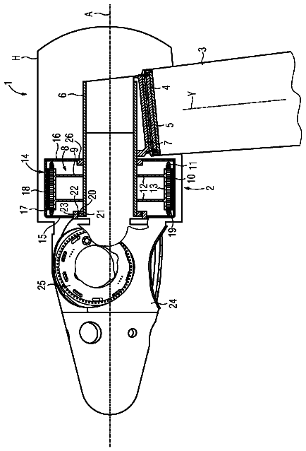
Wind turbine
A wind turbine which includes a direct drive generator is disclosed.
US 8,670,009 B2 · Assignee: NCR Corporation · Inventors: Lyons; Dale R. et al.
Sheet 1 of 18 from the published document. All sheets in the USPTO PDF
An apparatus and method for identifying a type of media installed in a two- or dual-sided thermal printer is provided. In one embodiment, one or more functions of the dual-sided thermal printer may be enabled or disabled depending on the identified media type.
Two, or dual-sided direct thermal printing of documents such as transaction documents and receipts is described in U.S. Pat. Nos. 6,784,906 and 6,759,366. In dual-sided direct thermal printing, the printers are configured to allow concurrent printing on both sides of thermal media moving along a feed path through the printer. In such printers a direct thermal print head is disposed on each side of the media along the feed path. In operation each thermal print head faces an opposing platen across the media from the respective print head. In direct thermal printing, a print head selectively applies heat to paper or other sheet media comprising a substrate with a thermally sensitive coating. The coating changes color when heat is applied, by which "printing" is provided on the coated substrate. For dual-sided direct thermal printing, the sheet media substrate may be coated on both sides.
1 of 18 drawing sheets so far from the published document, cropped to the drawing. Every sheet is in the USPTO PDF.
What the patent claimed, word for word. All of it is now free to use.
Two, or dual-sided direct thermal printing of documents such as transaction documents and receipts is described in U.S. Pat. Nos. 6,784,906 and 6,759,366. In dual-sided direct thermal printing, the printers are configured to allow concurrent printing on both sides of thermal media moving along a feed path through the printer. In such printers a direct thermal print head is disposed on each side of the media along the feed path. In operation each thermal print head faces an opposing platen across the media from the respective print head.
In direct thermal printing, a print head selectively applies heat to paper or other sheet media comprising a substrate with a thermally sensitive coating. The coating changes color when heat is applied, by which "printing" is provided on the coated substrate. For dual-sided direct thermal printing, the sheet media substrate may be coated on both sides.
A dual-sided direct thermal printer is configured to allow printing on both sides of a paper receipt, document, label or other thermal media moving along a feed path through the printer. In one embodiment, a dual-sided direct thermal printer comprises a thermal print head on each side of the media feed path and one or more media type sensors adapted to sense a type of media in the printer. In alternate embodiments, the dual-sided direct thermal printer may include an opposing platen disposed on each side of the feed path across from an associated print head and/or a guide roller on each side of said feed path. Dual-sided printer functionality, including identifying a type of media in the printer, may be controlled using commands implemented with, for example, setup configuration settings in hardware or software, escape sequences, real-time printer commands, and the like.
Dual-sided direct thermal printing provides for printing of variable information on both sides of a print media, such as a receipt, to save materials, and to provide flexibility in providing information to customers. The printing can be driven electronically or by computer using a computer application program which directs dual-sided printing.
FIG. 1A shows a schematic of a dual-sided imaging direct thermal printer useable for dual-sided printing of thermal media such as transaction receipts or tickets.
FIG. 1B shows a schematic of a dual-sided imaging direct thermal printer with one or more sensors for determining media type.
FIG. 1C shows an alternate schematic of a dual-sided imaging direct thermal printer with one or more sensors for determining media type.
FIG. 1D shows a further schematic of a dual-sided imaging direct thermal printer with one or more sensors for determining media type.
FIG. 1E shows a method of performing a print media check by a dual-sided imaging thermal printer.
FIG. 2A shows single-sided thermal media having a warning message printed on a first, thermal side, after a failed attempt to thermally image a second, non-thermal side.
FIG. 2B shows two-sided thermal media having a message printed on a second side after a successful attempt to thermally image a first side.
FIG. 2C shows non-thermal media after a failed attempt to thermally image first and second non-thermal sides.
FIG. 2D shows two-sided thermal media after an image in the form of a logo is thermally printed on a first and a second side thereof.
FIG. 3A shows a two-sided receipt with transaction detail printed on the front side.
FIG. 3B shows the receipt of FIG. 3A with supplemental information printed on the reverse side, such as variable stored information selected on the basis of the transaction detail.
FIG. 3C shows a two-sided receipt with a portion of the associated transaction detail printed on the front side of the receipt.
FIG. 3D shows the reverse side of the receipt of FIG. 3C on which the remaining portion of the associated transaction data is printed.
FIG. 4 shows a perspective view of an exemplary dual-sided direct thermal receipt printer for retail Point of Sale (POS) application.
FIG. 5 schematically shows a partial centerline cross-sectional view of the dual-sided direct thermal receipt printer of FIG. 4.
FIG. 6 schematically shows a partial gear plane cross-sectional view of the dual-sided direct thermal receipt printer of FIG. 4.
FIG. 7 schematically shows a partial centerline cross-sectional view of the dual-sided direct thermal receipt printer of FIG. 4, with a cover in an open position.
FIG. 8 schematically shows a partial centerline cross-sectional view of a variation of the dual-sided direct thermal receipt printer of FIG. 4.
FIG. 9 schematically shows a partial gear plane cross-sectional view of the dual-sided direct thermal receipt printer of FIG. 8.
FIG. 10 schematically shows a partial centerline cross-sectional view of a variation of the dual-sided direct thermal receipt printer of FIG. 4.
FIG. 11 schematically shows a partial gear plane cross-sectional view of the dual-sided direct thermal receipt printer of FIG. 10.
FIG. 12 schematically shows a partial centerline cross-sectional view of a further variation of the dual-sided direct thermal receipt printer of FIG. 4.
FIG. 13 schematically shows a further variation in a dual-sided direct thermal printer print head and platen orientation, and media feed path.
FIG. 14 schematically shows a further variation in a dual-sided direct thermal printer print head and platen orientation, and media feed path.
By way of example, various embodiments of the invention are described in the material to follow with reference to the included drawings. Variations may be adopted.
FIG. 1A shows a schematic of a dual-sided imaging direct thermal printer 10 useable for dual-sided printing of, for example, transaction receipts or tickets at time of issue. The printer 10 operates on print media 20 comprising, for example, double-sided thermal paper, e.g., comprising a cellulosic or polymer substrate sheet coated on each side with heat sensitive dyes as described in U.S. Pat. Nos. 6,784,906 and 6,759,366 the contents of which are hereby incorporated herein by reference. Substrates and heat sensitive color changing coatings for direct thermal printing media are generally well known in the art.
Dual-sided direct thermal printing can be facilitated by a media 20 which includes dyes on opposite sides of the media 20, and a sufficiently thermally resistant substrate to inhibit thermal printing on one side of the media 20 from affecting coloration on the opposite side of the media 20.
The thermal print media 20 may be supplied in the form of a paper roll, fan-fold stack, individual sheet and the like, upon which printing such as graphics or text, or both, may be printed on one or both sides of the media 20, to provide, for example, a voucher, coupon, receipt, ticket or other article or document.
As shown in FIG. 1A, the printer 10 has rotating platens 30 and 40 and opposing thermal print heads 50 and 60 on opposite sides of the thermal media 20. Dual-sided direct thermal printing of the media 20 may occur in a single pass at, for example, completion of a transaction such as when a receipt or ticket is issued. Alternately, dual-sided direct thermal printing may occur in a two or more pass process where, for example, the media 20 is imaged by one or both thermal print heads 50 and 60 when moving in a first direction, and then retracted for further imaging by one or both thermal print heads 50 and 60 with the media moving in either the first or a second, retract direction. Once printing is completed the media 20 may, depending on its format (e.g., roll, fan fold, individual sheets, and the like), be manually or automatically cut or severed to provide an individual receipt, ticket, or other document.
A dual-sided imaging direct thermal printer 10 may further include a switch 70 enabling activation and deactivation of one or more dual-sided printing modes or functions. Such dual-sided printing function switch 70 can be a mechanically operated switch on the printer 10, or an electronically operated switch operated by a printer driver on an associated host computer or by firmware or software resident on the printer 10, and the like. The switch 70 may, for example, be electronically operated in response to a command message or escape sequence transmitted to the printer 10. Printer control language or printer job language ("PCL/PJL"), or escape commands, and the like, may be used. A printer setup configuration program setting, e.g., a setting made through a software controlled utility page implemented on an associated host computer, could also electronically operate the function switch 70 for the dual-sided printer 10.
In one embodiment, the dual-sided printing function switch 70 may be configured, programmed or otherwise setup to select or otherwise identify
data for printing (e.g., internally stored macros, externally received transaction data, and the like),
which of the two thermal print heads 50 and 60 will be used to print and/or be used to print particular data,
whether selected data is to be printed when the media is moving in a first (e.g., forward) or second (e.g., backward) direction,
in which relative and/or absolute media location, including on which media side, particular data will be printed,
in which orientation (e.g., rightside-up, upside-down, angled, and the like) particular data will be printed on the media 20, and the like. For example, a setting of the dual-sided printing function switch 70 may marshal a portion (e.g., a first half) of a block of selected externally received and/or internally stored print data to be printed on a first (e.g., front) side of the media 20 and another portion (e.g., a second half) to be printed on a second (e.g., reverse) side of the media 20. A further setting may reverse the media sides on which the respective portions of data are to be printed. In this manner a document such as a transaction receipt may be generated in which a portion of the associated transaction data is printed on one side of the receipt and the remaining portion of the transaction data is printed on the other side of the receipt, conserving upon the amount of media 20 required for printing of the receipt. A dual-sided printing function switch may accordingly be configured, e.g., by a control command message transmitted to the printer 10, to determine, inter alia, the portion or quantity of data, or a block of data, to be printed on each side of the media. Different blocks of data, or portions thereof, may be alternatively selected and marshaled to different sides, or locations thereon, of the media 20 by the switch 70.
In one embodiment, a printing function switch 70 may select a first portion of print data for printing on a first side of thermal media 20, such as a receipt paper roll, and a second portion of print data for printing on a second side of the thermal media 20. Such print data may comprise data contemporaneously received by the printer 10 from a host computer such as a point-of-sale (POS) terminal (not shown), an automated teller machine (ATM) (not shown), a self-checkout system (not shown), and the like, and/or data stored in one or more memory or buffer locations 80 in the printer 10. It should be noted that print data may be
processed for printing before receipt by or storage in the printer 10 by, for example, a host computer such as a POS terminal,
processed for printing after receipt by or storage in the printer 10 by, for example, the printing function switch 70, or a controller or processor 90 associated with the printer 10, or
a combination of
and (2), among others. Likewise, such processing may occur before or after selection, identification and/or apportionment of the print data for printing on the first and/or second side of thermal media 20 by the printing function switch 70.
In another embodiment, a printing function switch 70 may be configured to select or otherwise identify print data for printing at a specified location, including a side, of the print media 20 based upon a quantity of media required to print such data. Such quantity may be determined based on, inter alia,
a physical, as-printed size (e.g., length, width, perimeter, area, font size, and the like) of the to-be-printed data,
a portion of the media 20 that is thermally imagable (e.g., a portion having one or more thermally sensitive coatings),
a portion of the media 20 which is pre-printed or pre-imaged,
a portion of the media 20 which is excluded or desired to be excluded from thermal or other imaging (e.g., margins, headers, line spacings, indentations, desired or required blank space, and the like),
physical characteristics of the printer 10 (e.g., size of the platens 30 and 40, size of the thermal print heads 50 and 60, spacing 35 of the platens 30 and 40, spacing 55 of the thermal print heads 50 and 60, and the like), and the like.
In an embodiment, a printing function switch 70 may apportion a first portion of print data for printing on a first side of media 20 and a second portion of print data for printing on a second side of the media 20, wherein the first and second portions are selected to occupy substantially the same amount of space on the respective first and second media sides when printed. Likewise, the printing function switch may apportion a first portion of print data for printing on a first side of the media 20 and a second portion of print data for printing on a second side of the media 20, opposite the first side, wherein the as-printed size of the first portion is selected to be greater than the as-printed size of the second portion. Differences in the as-printed size of the first and second data portions may be selected to accommodate, inter alia,
differences in an amount of printable space (e.g., accounting for margins, headers, footers, preprinted information, thermal coating coverage, and the like) between the first and the second sides of the media 20,
differences in the type of data (e.g., internally stored macro versus externally received transaction, and the like) selected for printing on a given side, and
differences in thermal print head location on the first and the second sides of the media 20 (e.g., print head space 55).
In one embodiment, the printing function switch 70 may apportion a first portion of print data, such as ticket information, for printing on a first side of the media 20 and a second portion of print data, such as a legal information, for printing on a second side of the media 20, opposite the first side, wherein the as-printed size (e.g., printed area) of the first portion is selected to be greater than the as-printed size (e.g., printed area) of the second portion by an amount substantially equivalent to an amount of printable space (e.g., area) on the second side of the media 20 between the thermal print heads 50 and 60. It should be noted that the as-printed size of the print data on a given side may be controlled by selection of an amount of data to be printed on a given side, selection of a size at which selected data is to be printed (e.g., font, font size, and/or data scaling), and the like.
In a further embodiment, apportionment of print data may be made by a printing function switch 70 such that a length of media 20 along a media feed path (e.g., following the arrow at the top of FIG. 1A) to be occupied by print data on a first side of the media 20 differs from a length of the media 20 along the media feed path to be occupied by print data on a second side of the media 20, by a length substantially equivalent to a spacing 35 between platens 30 and 40, a length substantially equivalent to a spacing 55 between the thermal print heads 50 and 60, and the like.
In one such case, first and second portions of data received by a printer 10, such as POS transaction data, may be identified by the printing function switch 70 such that a length of a first side of print media 20, such as a receipt, to be occupied by the first portion of the print data is greater than a length of a second side of the print media 20 to be occupied by the second portion of the print data by a length substantially equivalent to a spacing 55 between the first and the second thermal print heads 50 and 60. Other relevant lengths and/or variations in the apportionment of print data are, of course, possible. Additionally, the received print data may be stored in one or more buffers 80 of the printer 10 before or after identification by the printing function switch 70 for printing on one or both sides of the media 20.
In another embodiment, data selected or otherwise identified for printing on one or both sides of media 20 by the printing function switch 70 may include predefined print data or macros, such as one or more of a location identifier (e.g., address), an establishment identifier (e.g., store), a computer identifier (e.g., POS terminal), a logo, an advertisement, and the like, stored in one or more memories associated with the printer 10. In one example, some or all of such predefined print data may be selected for printing in the space 55 between the first and the second thermal print heads 50 and 60 on one or both sides of the media 20. Further, such information may be selected for printing in advance of any contemporaneously received print data, such as transaction data received from a POS terminal, which is to be included on, for example, the same document or receipt. As such, predefined print data may be selected for printing on regions of the media 20 where it may otherwise be difficult or undesirable for printing of contemporaneous information to occur, such as a region of media 20 between the first and second thermal print heads 50 and 60, thereby maximizing use of the media 20.
In a further embodiment, the printing function switch 70 may apportion print data, including internally stored macros and/or received transaction data, among a first and a second side of the thermal media 20 in order to optimize use of the media. In performing such optimization, the printing function switch may control the as-printed size (e.g., font, font size, scaling, and the like) of selected print data. Likewise, the printing function switch 70 may take account of, inter alia,
media size and design parameters including desired or required headers, footers, margins, and the like,
thermally sensitive coating location(s), and
any information that may be preprinted on the media 20. In one embodiment, such accounting may comprise the printing function switch 70 avoiding apportionment of some or all of the selected print data to certain media regions such as regions where preprinted data exists, apportioning of some or all of the selected print data to other media regions such as regions set off by one or more sensemarks, and the like. Further, in other embodiments, one or more sensors 100, such as one or more optical sensors, may be used to sense regions of preprinted information and/or regions demarked by one or more sensemarks for making apportionment and non-apportionment decisions as part of such print media use optimization.
Additionally or alternatively, one or more sensors 100 may be used to ascertain a type of media 20 (e.g., single-sided thermal, double-sided thermal, non-thermal, label, roll, fan-fold, preprinted, and the like) loaded into the printer 10. Signals from such sensors may then be used to, inter alia, provide notification to an operator of the type of media 20 in the printer 10, and/or enable or disable one or more functions of the printer 10 based on the sensed media type.
In one embodiment, one or more sensors 100 may be used to sense whether thermal printing has occurred on one or both sides of installed media 20 after an attempt to image by a first and/or a second thermal print head 50 and 60. A signal indicative of success or failure to sense expected thermal printing from the one or more sensors 100 may then be used to provide an indication of such success or failure to an operator, such as by providing an audible, visual and/or tactile notification, printing a message on one or more sides of the installed media, and/or sending a signal to an attached computer, such as a POS terminal, an ATM, a self-checkout system, and the like, for triggering generation of an operator notification. Likewise, a signal from the one or more sensors 100, such as a signal indicative of success or failure to sense expected thermal printing, may be used to enable or disable one or more dual-sided imaging direct thermal printer 10 functions, such as printing by one or more thermal print heads 50 and 60, advancement of the media 20, operation of a cutting mechanism (e.g., knife blade mechanism 370 in FIG. 5), motion (e.g., rotation) of one or more platens 30 and 40, operation of a drive and/or stepper motor (not shown), and the like. Further, one or more codes indicative of the success or failure to sense expected thermal printing on one or both sides of the installed media 20 may be saved to a memory or buffer 80 of the printer 10 for reporting, diagnostic and/or printer control (e.g., print mode setting) use.
In one embodiment, shown in FIG. 1B, one or more sensors, such as a sensor 100, may be placed on one side of a print media feed path, proximate to a thermal print head, such as first thermal print head 50, for sensing, inter alia, one or more media properties, conditions or features. The sensor 100 may be a motion sensor, a hall effect sensor, an infrared (IR) sensor, an ultraviolet (UV) sensor, a radio frequency (RF) sensor, a charge coupled device (CCD), and the like. In one embodiment, the sensor 100 comprises an optical sensor adapted to produce a signal indicative of printing, such as thermal printing, on print media 20.
In operation, an attempt may be made by the dual-sided imaging direct thermal printer 10 to thermally image the media 20 using the first thermal print head 50. During such attempt, print data may be selected from a memory or buffer 80 for printing by the first thermal print head 50. If, after an attempt by the first thermal print head 50 to print, the sensor 100 does not sense the selected print data, a print failure signal may be generated. Such print failure signal may then be used to generate one or more internal (e.g., printer 10) and/or external (e.g., connected computer or terminal) notifications for an operator, and/or enable and/or disable one or more printer 10 functions, such as disabling further printing by the first thermal print head 50.
In one embodiment, one or more sensors, such as a sensor 100, will be found to have not sensed the selected print data where a signal from the sensor 100 does not match, to within a desired tolerance, a signal expected from the selected print data. Such expected signal may be stored in a memory or buffer 80 of the printer 10, and compared to a signal from the sensor 100 by, for example, a controller or processor 90 associated with the printer 10. Such controller or processor 90 may, then, generate a further signal indicative of the type of media installed in the printer 10 (e.g., single-sided thermal, double-sided thermal, or non-thermal) on the basis of such comparison, which further signal may be used to provide an operator notification and/or automatically enable and/or disable one or more printer functions.
One or more generated operator notifications may indicate the media 20 is not thermally coated on the side of the media 20 sought to be imaged by the first print head 50 (e.g., the media 20 is not double-sided thermal media). In one case, such a notification may further include an indication to an operator to replace the installed media 20 with proper (e.g., double-sided thermal) media 20. Additionally or alternatively, such indication may provide an operator with an option to continue using the installed media 20 with the first thermal print head 50 disabled from further printing. In alternate embodiments, such disablement may be automatic, and may require further printer 10 or operator input or action to override and/or otherwise change. Additional media types, such as single-sided thermal media coated on a side imagable by the first thermal print head 50 may also be selected and/or indicated for use.
Where required or desired, operator input may be provided directly through one or more printer 10 input devices, such as one or more switches, accessible to an operator. Additionally or alternatively, operator input may be provided through, for example, an attached, operator accessible terminal, such as a POS terminal (not shown) adapted to send control and/or configuration information to the printer 10 in the form of, for example, one or more escape sequences. In one embodiment, operator input is provided through and/or maintained by a printing function switch 70.
In another embodiment, shown in FIG. 1C, one or more sensors, such as a sensor 102, may be placed on one side of a print media feed path, proximate to a thermal print head, such as second thermal print head 60, for sensing, inter alia, one or more media properties, conditions or features. As described above, the sensor 102 may be a motion sensor, a hall effect sensor, an IR sensor, an UV sensor, a RF sensor, a CCD, and the like. In one embodiment, the sensor 102 comprises an optical sensor adapted to produce a signal indicative of printing, such as thermal printing, on print media 20.
In operation, an attempt may be made by the dual-sided imaging direct thermal printer 10 to thermally image the media 20 using the second thermal print head 60. During such attempt, print data may be selected from a memory or buffer 80 for printing by the second thermal print head 60. If, after an attempt by the second thermal print head 60 to print the selected data, the sensor 102 does not sense the selected print data, a print failure signal may be generated. Such print failure signal may then be used to generate one or more internal (e.g., printer 10) or external (e.g., connected computer or terminal) notifications for an operator, and/or disable one or more printer 10 functions, such as disabling further printing by the second thermal print head 60.
Additionally or alternatively, if, after an attempt by the second thermal print head 60 to print the selected data, the sensor 102 does sense the expected print data, a print success signal may be generated. Such print success signal may then be used to generate one or more internal (e.g., printer 10) or external (e.g., connected computer or terminal) notifications for an operator, and/or disable and/or enable one or more printer 10 functions, such as enabling further printing by the second thermal print head 60.
In one embodiment, one or more sensors, such as a sensor 102, will be found to have sensed the selected print data where a signal from the sensor 102 matches, to within a desired tolerance, a signal expected from the selected print data. Such expected signal may be stored in a memory or buffer 80 of the printer 10, and compared to a signal from the sensor 100 by, for example, a controller or processor 90 associated with the printer 10. Such controller or processor 90 may, then, generate a further signal indicative of the type of media installed in the printer 10 (e.g., single-sided thermal, double-sided thermal, or non-thermal) on the basis of such comparison, which further signal may be used to provide an operator notification and/or automatically enable and/or disable one or more printer functions.
One or more such notifications may indicate the media 20 is thermally coated on the side of the media 20 sought to be imaged by the second thermal print head 60. In one case, such notification may further include an indication to an operator that proper media 20 is installed in the printer 10 and continued printer 10 operation may proceed. Additionally or alternatively, such indication may provide an operator with an option to use the installed media 20 with the second thermal print head 60 enabled whether such operation was previously enabled or disabled.
As previously described, enablement and/or disablement of one or more thermal print heads 50 and 60, or other printer component or functionality, may automatically occur in response to a signal from one or more print sensors 100 and 102, and may require further printer 10 or operator action to thereafter change. In one such embodiment, operation of a first and/or a second thermal print head 50 and 60 may be re-enabled following a prior, automatic disablement upon successful sensing of thermal printing by a sensor 100 or 102.
In yet another embodiment, shown in FIG. 1D, one or more sensors, such as a first sensor 100, may be placed on a first side of a print media feed path, proximate to a thermal print head, such as a first thermal print head 50, for sensing, inter alia, one or more properties, conditions or features of a first side of print media 20, and one or more sensors, such as a second sensor 102, may be placed on a second side of the print media feed path, proximate to a thermal print head, such as a second thermal print head 60, for sensing, inter alia, one or more properties, conditions or features of a second side of the print media 20. As previously described, the sensors 100 and 102 may each comprise a motion sensor, a hall effect sensor, an IR sensor, an UV sensor, a RF sensor, a CCD, and the like. In one embodiment, each of the sensors 100 and 102 comprise an optical sensor adapted to produce a signal indicative of printing, such as thermal printing, on a respective side of installed print media 20.
In operation, an attempt may be made by the dual-sided imaging direct thermal printer 10 to thermally image the media 20 using the first and the second thermal print heads 50 and 60. During such attempt, first print data may be selected from a first memory or buffer 80 for printing by the first thermal print head 50, and second print data may be selected from a second memory or buffer 80 for printing by the second thermal print head 60. If, after an attempt by the first thermal print head 50 to print it, the sensor 100 does not sense the selected first print data, a first print failure signal may be generated. Such first print failure signal may then be used to generate one or more internal (e.g., printer 10) or external (e.g., connected computer or terminal) notifications for an operator, and/or to automatically enable or disable one or more printer 10 functions, such as further printing by the first thermal print head 50. Likewise, after an attempt by the second thermal print head 60 to print it, if the sensor 102 does not sense the selected second print data, a second print failure signal may be generated by the sensor 102. Such second print failure signal may then be used to generate one or more internal (e.g., printer 10) or external (e.g., connected computer or terminal) notifications for an operator, and/or to automatically enable or disable one or more printer 10 functions, such as further printing by the second thermal print head 60.
Where one or more sensors 100 and 102 are installed proximate to first and second thermal print heads 50 and 60, a multitude of operations and/or notifications are possible. For example, in one embodiment, thermal media may be indicated by a first sensor 100, and non-thermal media may be indicated by a second sensor 102, resulting in an indication of the installation of single-sided thermal media 20 oriented for printing on a first side by the printer 10. In such case, a first thermal print head 50 may be manually or automatically enabled for printing while a second thermal print head 60 may be manually or automatically disabled for printing. Similarly, in another embodiment, non-thermal media may be indicated by a first sensor 100, and thermal media may be indicated by a second sensor 102, resulting in an indication of the installation of single-sided thermal media 20 oriented for printing on a second side by the printer 10. In such case, a first thermal print head 50 may be manually or automatically disabled for printing while a second thermal print head 60 may be manually or automatically enabled for printing. In each of the above noted cases, one or more operator notifications, such as the printing of a message indicating single- or non-double sided thermal media is installed by a respective, operative thermal print head, may also be provided.
In yet another embodiment, thermal media 20 may be indicated by both a first and a second sensor 100 and 102, resulting in an indication that double-sided thermal media is installed for printing on both a first and a second side thereof. In such case, printing by either or both a first and a second thermal print head 50 and 60 may be manually and/or automatically enabled. Similarly, in still another embodiment, non-thermal media may be indicated upon indication of non-thermal media by both the first and the second sensors 100 and 102. In such case, printing by both a first and a second thermal print head 50 and 60 may be manually and/or automatically disabled, and/or an operator notification, such as one or more audible, visual and/or tactile alarms indicating non-thermal media is installed, may be provided.
In all cases, enablement and/or disablement of one or more print functions, such printing by the first and/or second thermal print heads 50 and 60, may be automatically provided for in response to one or more signals from the one or more sensors 100 and/or 102. Likewise, enablement and/or disablement of one or more print functions may be provided for via manual print mode selection following operator notification. Variations of the above, including combined manual and automatic schemes (e.g., automatic print mode selection with manual operator override), are also possible.
In alternate embodiments, a result from a print media type determination may be compared to one or more print mode settings in advance of, for example, manually or automatically making changes to one or more printer functions. Such print mode settings may be stored in one or more memories or buffers 80 of the printer 10. In one embodiment, where the printer is set for single-sided printing on a first side of thermal media 20, no manual or automatic change to the print mode may be warranted or made where the installed media is determined to be double-sided thermal media or single-sided thermal media oriented for printing on the first side. However, where the printer is similarly set for single-sided printing on a first side of thermal media 20, manual and/or automatic change to the print mode may be required or made where the installed media is determined to be single-sided thermal media oriented for printing on a second side. Additional combinations and/or variations on the above scenarios are, or course, possible. Further, where a conflict exists between a detected media type and one or more print mode settings, a user may be prompted to change and/or replace the media 20 in addition to, or instead of the making of any manual and/or automatic printer function and/or mode modification.
In practice, a dual-sided direct thermal imaging printer 10 may be configured to manually and/or automatically perform a print media type check operation in response to, inter alia, a variety of printer operations, conditions and/or inputs. For example, in one embodiment, a print media check may occur on-demand (e.g., operator selected). In another embodiment, such print media check may be periodic, occurring, inter alia, at one or more fixed times and/or intervals. Additionally or alternatively, such print media check operation may be triggered by a particular event including, inter alia, power-on of the printer 10, connection of the printer 10 to an external device such as a computer or terminal (not shown), and/or replacement of media 20.
In case of replacement or replenishment of print media 20, a print media check may be triggered by one or more signals from one or more media sensors associated with the printer 10. Such media sensors may include one or more of a media installed sensor, and a media quantity sensor, as well as one or more media type sensors. In one embodiment, a media-in signal following a media-out signal (e.g., media replenished) may trigger execution of a print media check. Likewise, in case of a power-on of the printer 10, a print media check may be performed as one of an array of pre-operational printer diagnostics.
Regardless, initiation of a print media check may occur in response to a single trigger or command, or a print media check may occur as a result of multiple triggers or commands. Similarly, initiation of a print media check may require additional signals be provided, and/or permissives be met, as a condition precedent to execution of a print media check. Such additional signals or permissives may include a printer closed signal provided by, inter alia, one or more contact or limit switches (see, e.g., limit switch 420 in FIG. 6), a print media check data storage permissive indicating a block of print data for performing a media check is stored in a memory of buffer 80 of the printer 10, and the like. In one embodiment, a printer 10 may be configured to not perform a print media check where a media sensor indicates no media is installed and/or media is improperly installed in the printer.
FIG. 1E illustrates one embodiment of a method 600 of performing a print media check by a dual-sided imaging thermal printer 10. Initially, in step 610, a command or other trigger to initiate a print media check is received and/or processed by the printer 10. In step 620, one or more permissives are checked to verify one or more conditions precedent to performing the media check are met. Such permissives may include, inter alia, a signal from a paper sensor (e.g., paper sensor 360 in FIG. 5) indicating there is media 20 in the printer 10, a signal from one or more limit switches 420 indicating the printer 10 is properly assembled for printing (e.g., a pivotable support arm or cover 300 in FIG. 6 is properly closed and/or mated to a lower arm or base of a printer 200), a signal indicating a print transaction has been completed, a signal indicating a proper print test message is in a memory or buffer 80, and/or one or more signals indicating motor, voltage, and thermal print head 50 and 60 status are suitable (e.g., there are no fault conditions) for printing.
Once the one or more permissive have been met, in step 630 print media check data is obtained (e.g., received and/or retrieved) for attempted printing by the first and/or the second thermal print heads 50 and 60. Such print media check data may comprise text (e.g., ASCII, Kanji and the like) and/or graphics, and include one or more messages (e.g., messages 708 and 728 in FIGS. 2A and 2B), one or more images (e.g., images 706 and 726 in FIGS. 2A and 2B), one or more logos (e.g., logo 766 in FIG. 2D), and the like. In one embodiment, print media check data comprises one or more bar codes or other machine readable symbologies (e.g., bar codes 710, 746 and 748 in FIGS. 2A, 2B and 2C). Further, print media check data may be received from a computer or terminal in communication with the printer 10, or retrieved from one or more memories or buffers 80 associated with the printer 10. In one embodiment, the print media check data is retrieved from an EEPROM associated with the printer 10.
The description continues in the full USPTO document.
About 6,714 words. The USPTO PDF has it with every drawing.
Fees are due 3.5, 7.5 and 11.5 years after grant. This patent expired on March 11, 2026, so the fee marked "not paid" was the one that went unpaid.
Two-sided thermal print sensing
Filed Dec 2006 · published Sep 2007Two-sided thermal print sensing
Filed Dec 2006 · granted Mar 2014Earlier publications, parents and continuations. None of them can still be enforced, or this patent would not be listed.
Prior art cited by the examiner or applicant. Useful when you check your own idea for novelty.
Everything on this page comes from the documents linked above.


