Cross-reference to related applications
This application is an U.S. national phase application under 35 U.S.C. .sctn.371 based upon co-pending International Application No. PCT/GB2009/001718 filed on Jul. 10, 2009. Additionally, this U.S. national phase application claims the benefit of priority of co-pending International Application No. PCT/GB2009/001718 filed on Jul. 10, 2009, and Great Britain Application No. 0812739.1 filed on Jul. 11, 2008. The entire disclosures of the prior applications are incorporated herein by reference. The international application was published on Jan. 14, 2010 under Publication No. WO2010/004293.
Background
1. Field of the invention
The present invention relates to a method and apparatus for generating energy from the motion of waves in a body of water, such as seas, oceans and lakes.
The purpose of this invention is to enable the harvesting of renewable wave energy from the oceans and lakes of the world.
2. Description of the prior art
Many devices have been proposed in the past to accomplish this purpose. Very few have become commercialized because of one or more of the following reasons;
1/The device is too expensive to produce and hence unable to compete with conventional fossil fuel means of energy production.
2/Many of the devices are of high complexity. Components such as springs, running rigging, pulleys, bearings, gearboxes and other rotating equipment, electrical or electronic controls, all have limited service lives, especially in a marine environment.
3/Many of the devices attempt to generate electricity at sea and then to transmit it ashore. Water, especially sea water and electricity, like water and oil, do not mix. Any attempt at doing this will result in high construction costs and long term unreliability due to faults and corrosion problems.
4/Many devices are unable to withstand storms and high waves.
5/Many devices have not taken into account the long term serviceability and maintenance requirements which are necessary to achieve a life expectancy of at least 20 years, which is the industry norm.
6/Many devices require the use of oils, heavy metals and other materials which, if released, can be potentially damaging to the environment.
Accordingly, there is a need for an improved system and method for generating energy from waves in bodies of water that addresses some or all of the above problems.
The prior art describing devices for the capture of sea wave energy is extensive. Prior art which is closely related to the this proposed device is however limited to a few examples. The most relevant are as follows;
WINDLE, EP 0265594 discloses a float operated reciprocating pump which relies upon springs, or weights or floats with or without ropes and pulleys to actuate the return stroke. Windle also discloses the various configurations of mounting a reciprocating pump with respect to the float and foundation. The pump may be inverted, may be mounted within the float or within the sea bed or in other configurations.
JANODY, FR 2800423 also discloses a spring to actuate the return stroke.
BURNS, CA 2619100 discloses a pump utilizing a hollow piston but only proposes using gravity to actuate the return stroke.
ONO, U.S. Pat. No. 4,398,095 discloses a hydraulic method of actuating the return stroke by utilizing the pressure difference between air at the surface and the pressure of the water at depth.
WOOD, GB 2 428 747 discloses a wave energy system with a float moored to a single hydraulic cylinder.
Similarly, HICKS et al., U.S. Pat. No. 4,326,840 discloses a wave driven pump having a float moored to a hydraulic cylinder at the seabed. A wave powered pumping apparatus and method are also disclosed by WINDLE, U.S. Pat. No. 4,883,411.
Wave energy systems are also disclosed by MYUNG, GB 2281943 and SMITH, GB 2445951.
Summary of invention
The intention of the present invention is that a wave actuated pump would be deployed either singly or preferably in groups or arrays of multiple pumping units. The discharge pipe of each of these pumps would be connected to a system of underwater discharge pipes which would thence be connected to the shore to deliver pressurized water for any purpose but preferably for the purpose of electricity generation or the desalination of sea water. This method of power transmission is well known, an example is the London Hydraulic Power company which in 1890 installed a system of pressurized water pipes in London, England for the purpose of transmitting power from various pumping stations to factories and other users. The generation of electricity and or production of desalinated water from hydraulic power is well understood by those knowledgeable in the art.
This invention is a reciprocating pump device, connected to the sea bed, which is operated by the upward force created by the buoyancy of a float which follows a rising wave on the water surface which causes fluid to be expelled from the pump into a discharge pipe. A portion of this pumped fluid is stored in a pressure accumulator connected to the discharge pipe or pipes. As the wave descends, a small amount of the pressurized fluid in the discharge pipe returns to the pump to activate its return stroke and also to maintain a downward force on the float so that it will tend to retain its position vertically above the point of connection on the sea bed.
According to a first aspect of the present invention, there is provided a float operated reciprocating pump comprising:
a float;
a closed cylinder connected to one of the float or the seabed and having a fluid inlet and a fluid discharge;
a piston disposed within the cylinder and moveable longitudinally therein, the piston having a passage extending longitudinally therethrough;
a fluid check valve disposed to communicate with the passage through the piston;
a first rod or tube connected to the piston and extending through one end of the closed cylinder and further connected to other of the float or the seabed;
a second rod or tube having a larger diameter than the diameter of the first rod or tube extending through the other end of the closed cylinder.
In one embodiment, the present invention provides a float operated reciprocating pumping device, comprising a float operably connected to one end of a rod or tube disposed slidably and sealably through one end of a closed cylinder, the other end of said rod or tube connected to one end of a piston disposed slidably and sealably within said cylinder, said piston having a passage between its ends and a check valve disposed to communicate with said passage, the other end of said piston connected to a second larger diameter rod or tube disposed slidably and sealably through the other end of said cylinder, said cylinder fitted with inlet means and a discharge pipe, said cylinder operably connected to the sea bed.
In an alternative embodiment, the present invention provides a float operated reciprocating pumping device as hereinbefore described, except that the float is operably connected to the cylinder and the first rod or tube is operably connected to the sea bed.
In use, the float of the pump is disposed to be acted upon by the waves in the body of water. The apparatus may be used in any body of water in which waves are propagating, including seas, lakes, oceans, rivers, estuaries or the like. References herein to `sea` and `seabed` are not limiting and are understood to be references to all other such bodies of water.
The second rod of tube is most preferably a tube, providing a conduit for fluid to entering and leave the cylinder therethrough.
In one preferred embodiment, the inlet of the cylinder is provided with a check valve mounted to communicate between the exterior and interior of said cylinder. The check valve may be in any suitable position in the wall of the cylinder, preferably in a position adjacent to or within the cylinder end through which the second larger diameter rod or tube passes.
In one preferred embodiment, the second larger diameter rod or tube is a tube and the inlet of the cylinder comprises a check valve mounted to communicate with the interior of said tube, wherein the interior of said tube also communicates with the cylinder via a port in the wall of said tube. Preferably, port is positioned adjacent to the connection of the tube with the piston.
This invention also relates to the method and means of deploying and retrieving the device.
This invention also relates to the method and means for protecting the device during storms.
This invention also relates to the geometry of the float with respect to self protection from storm damage and to the optimal capture of wave energy.
The invention herein disclosed overcomes all of the above mentioned drawbacks to previous inventions as follows;
1/The invention herein disclosed may be constructed from readily available materials and components and is easily manufactured using mass production techniques, hence its cost will be low.
2/The invention herein disclosed is of low complexity with very few moving parts.
3/The invention herein disclosed has no requirement for electrical generating equipment at sea.
4/The invention herein disclosed may be provided to have at least two means of protection from storms and high waves.
5/The invention herein disclosed is suitable for being built from generally very hard, long lasting materials to ensure an adequate working life. A method and means is also proposed for deployment and retrieval of the device so that it may be serviced or repaired when necessary.
6/The invention herein disclosed may avoid the use of materials which are known to be damaging to the environment.
Brief description of the drawings
Embodiments of the present invention will now be described, by way of example only, having reference to the accompanying drawings.
I now refer you to the drawings, FIG. 1, FIG. 2 and FIG. 3
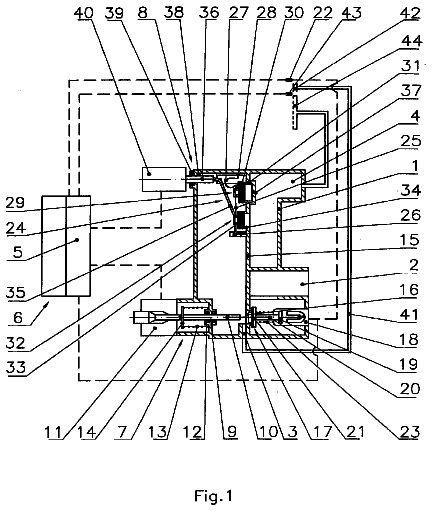
FIG. 1 is a drawing of the complete pump assembly of one embodiment of the present invention.
FIG. 2 is a drawing of another embodiment of the pump of the present invention.
FIG. 3 is an enlarged drawing of one embodiment of the mechanism which connects or disconnects the pump to its foundation on the sea bed
Referring first to FIG. 1, I will now describe the pump and its operation in detail.
Description of the preferred embodiment
Description of Pump
A float
which may be constructed of any buoyant material including a vessel containing or not containing a gas. The geometry of the float should be large in its horizontal dimension and relatively small in its vertical dimension. The float should have a streamlined shape in order to have minimum drag to water approaching it in the horizontal direction. There are several reasons for this shape. The large surface area will allow the float to absorb both the kinetic and the potential energy from the rising waves. The float will deliver its maximum buoyancy force with only a small rise in the wave. The streamlined shape will minimize the lateral displacement of the float caused by wave action or by prevailing currents, or when it is submerged during storms. The float described above is connected by links or clevis or toggle to a flexible rope or chain or rod or tube
which itself is connected in a similar manner to one end of the rod or tube (3). The other end of this rod or tube is rigidly connected to one end of the piston (2). Piston
is hollow to allow the passage of fluid to check valve
which is mounted within or close to the piston
Another rod or tube (4), which is larger in diameter than rod or tube
is rigidly connected to the other end of piston (2). In the preferred embodiment of the invention rod or tube
is a tube with check valve
mounted within its length or at its end. In another embodiment, described below, it is a rod or a sealed tube without a check valve. Piston
along with part of the rods or tubes (3,4) and the check valves (9,10) are enclosed in cylinder (1), inside of which the piston
can slide freely. Cylinder (1), which can be any length, is closed at both ends except to allow the passage of rods or tubes (3,4) and has a buoyant collar
attached to one end. Each closed end of the cylinder is fitted with a seal (7,8) which can be any type of seal including the preferred controlled clearance type. Piston
divides this cylinder
into two pumping chambers (10 and 18). Ports or openings (11 and 12) allow passage of fluid between these chambers via the hollow piston and check valve (9). The end of cylinder
adjacent to rod or tube
has an opening or port connected to the discharge pipe (5). Discharge pipe
may be all flexible pipe or part rigid and part flexible. The other end of discharge pipe
may be either connected directly to the shore or in the preferred embodiment will be connected to the mechanism which connects or disconnects the pump from its foundation on the sea bed. This mechanism will be described later in this text. In the preferred embodiment, the discharge pipe
is connected to a three way service valve
which is remotely operable from the sea surface. A pressure accumulator
is connected to the discharge pipe or pipes
at some point along its length. Support structure
is rigidly connected to cylinder
at one end and to the flexible joint
at its other end. This support structure
may be open to the sea or may include a filter or screen attached to its surface. In another embodiment it may be a cylinder closed at its ends with an inlet port (6). This inlet port may be connected to any source of fluid or may be open to the sea or may be connected to any type of filtration or pretreatment equipment.
Operation of Pump
To better explain the means of operation of this invention, I will start by assuming that the float
is static, the accumulator
is pressurized above the ambient pressure of the environment of pump, the accumulator
is charged with fluid and the pump is full of fluid. In this condition check valve
is closed and pumping chamber
is pressurized by the accumulator (30). Pumping chamber
is also equally pressurized via the piston (2). An axial force is generated on rod or tube
by the pressure difference between its ends. A similar, but opposite, axial force is generated on rod or tube
by the pressure difference between its ends. Rod or tube,
is larger in diameter than rod or tube
and hence the magnitude of the force on rod or tube
is greater. The resultant of these forces is a net downward force on the operably connected float (14). This force will be balanced by a portion of the buoyancy of float
to keep the system in equilibrium. By this means the whole pump string, from float to foundation, is maintained in tension. If now we assume that a rising wave acts upon the float
an upward force will be generated by both the kinetic energy of the rising water and by the increasing buoyancy of the float. This force will overcome the above mentioned downward force and the float
along with the operably connected piston
will move relative to the cylinder
causing volume reduction of pumping chamber (19), closing of check valve
and hence displacement of fluid into the discharge line (5). Simultaneously, pumping chamber
will increase in volume causing fluid to enter it via check valve
and port (11). When the float has reached the top of the wave and the wave then begins to descend check valve
opens, check valve
closes, and the above mentioned force due to the difference in diameter of rods or tubes (3 and 4) will cause the piston
to move, relative to the cylinder (1), in an opposite direction to the first stroke therefore causing pumping chamber
to expand and pumping chamber
to contract. Fluid will therefore pass through the hollow piston via port (11), check valve
and port
from pumping chamber
to pumping chamber (19). The pump is thus reset and ready for the next pumping stroke caused by the next rising wave. The piston
may be at any position within the length of cylinder
when this next pumping stroke commences or finishes. By this means the pump will self adjust for any variation in water depth caused by, for example, tides. The three way service valve
is used for isolating the device from the rest of the discharge pipe or pipes
so that it may be retrieved for servicing or repair.
I now refer to FIG. 2
Description of Pump
This figure shows another embodiment of the device which differs in the position of the inlet and the check valve. The description is the same as the description of the embodiment in FIG. 1 except for the following changes. In this embodiment the inlet port
is located at the opposite end of cylinder
from the discharge pipe (5). The inlet check valve
is located within or adjacent to this port. Rod or tube
is a rod or a sealed tube without a check valve. Port
may be connected to any source of fluid or may be open to the sea or may be connected to any type of filtration or pretreatment equipment.
Operation of Pump
The operation of the pump is the same as the embodiment in FIG. 1 except that the incoming fluid now passes through port
and check valve
directly into pumping chamber (18).
Other Configurations
Either of the above mentioned embodiments may be configured with the pump in an inverted position with the float operably connected to the cylinder and the piston operably connected to the sea bed. That is rod or tube
could be connected to flexible joint
and cylinder
could be connected to flexible rope or chain or rod or tube (15). The construction and operation of the pump would be essentially the same as described above.
I now refer to FIG. 3
Description of the Mechanism which Attaches the Pump to the Sea Bed
FIG. 3 shows the mechanism which may connect or disconnect the pump from the foundation.
Flexible joint
which can be a toggle, clevis, chain, rope, link or any type of flexible member connects the pump assembly to this mechanism. The other end of flexible joint
is rigidly connected one end of pin (25). Pin
is hollow through part of its length. Discharge pipe
is connected to pin
so as to communicate with its hollow part. A port (33), located further along the pin, communicates with the hollow part and also with the outside of the pin. The other end of pin
has a groove and is is tapered and connected to the actuation line
which can be a rope or tether or cable or chain which extends via pulley
and via the fairlead on lock
to and beyond the surface of the sea. The receptacle
accommodates this pin
and is fitted with two seals (34). Between the seals
is an annular groove in the receptacle
which communicates with the discharge pipe (21). The lock
rotates horizontally about a pivot and is shaped to engage the groove on pin (25). Incorporated in the lock
is a fairlead. The receptacle
is rigidly attached to the foundation
by a support structure (28).
FIG. 3 also shows the foundation
which can be a gravity foundation constructed from concrete, metal or any other dense material. Foundation
may also be an anchor of any kind including screws, piles and plates which are installed below the sea bed.
Operation of the Mechanism which Attaches the Pump to the Sea Bed
The foundation and mechanism shown in FIG. 3 is mounted on the sea bed with a known orientation. To deploy the pump, the upper end of actuation line
is connected to a motor boat or other vessel. The motor boat applies tension to the actuation line
thus drawing pin
and hence the operably attached pump down to and into the receptacle (26). The motor boat, still maintaining tension on the actuation line (23), navigates in an arc around the device. This motion of the motor boat causes the actuation line
to bear against the fairlead portion of the lock
thereby causing it to rotate about its pivot and engage the groove in pin (25). The actuation line
is now disconnected from the motor boat and is attached to any object at the surface ready for later retrieval. Retrieval of the device is carried out in the same manner, except that the motor boat navigates an arc in a reverse direction to that which was used to deploy the device, causing the lock
to disengage from the groove in pin
thus releasing the device from the receptacle (26). The buoyant collar FIG. 1
causes the disconnected pump to rise to the surface.
Operation of the Pump or Pumps During Storms
At some point along the discharge pipe or pipes (21), but beyond the pressure accumulator (30), a valve or valves
may be fitted. This valve or valves
may be closed to prevent fluid flow out of the discharge pipe
of the pump hence preventing movement of the piston
on its pumping stroke. Pressurized fluid from the accumulator will continue to activate the return stroke therefore causing the float (14), which is operably connected to the piston (2), to descend to the level of the lowest wave trough. As the wave rises the float will submerge below it and by this means protect itself from damage from the large forces which would be generated in the crest of a storm induced wave. Resilient stops may also be fitted within the cylinder
or attached to the ends of piston
to restrict the motion of the piston and hence the operably connected float.
 Lapsed, fee not paid4 drawings