 Lapsed, fee not paid15 drawings
Vehicles & Drones · US 8,668,238 B2
Glove box structure for vehicle
A glove box structure for a vehicle includes a storage portion and a lid portion.
US 8,668,248 B2 · Assignee: Honda Motor Co., Ltd. · Inventors: Ishizono; Manabu et al.
Sheet 1 of 49 from the published document. All sheets in the USPTO PDF
A vehicle body (11) including: a tunnel cross-member (28) extending in the vehicle's widthwise direction along the lower surface of a tunnel section (18) of the floor panel (19); left and right side-frame extensions (22, 22) extending rearward along the lower surfaces (31, 32) of the dashboard (15) from the rear ends of left and right front side-frames (16, 16). The left and right side-frame extensions each bifurcate into a side sill-side extension (43, 43) which, while tilting, extends rearward and outward in the vehicle's widthwise direction from the rear end of each of the left and right side-frame extensions to a side sill (17, 17), and into a tunnel-side extension (44, 44) which, while tilting, extends rearward and inward in the vehicle's widthwise direction from the rear end of each of the left and right side-frame extensions to the tunnel cross-member. The tilt of the side sill-side extensions and the tilt of the tunnel-side extensions are substantially the same.
Patent Document 1 discloses a vehicle body in which a fuel tank is disposed below a driver's seat and below a front floor panel. A summary of a front portion of the vehicle body disclosed in Patent Document 1 is described with reference to FIG. 56 hereof. FIG. 56 diagrammatically shows a planar structure of the front portion of the vehicle body disclosed in Patent Document 1. A front portion of a vehicle body 200 disclosed in Patent Document 1 accommodates left and right front side frames 201, 201 positioned on opposite sides in the vehicle-width direction, left and right floor frames 202, 202 extending rearward from the rear ends of the left and right front side frames 201, 201, and left and right side sills 203, 203 positioned outside the left and right floor frames 202, 202 in the vehicle-width direction, as shown in FIG. 56. A front floor panel 204 runs between the left and right sid
1 of 49 drawing sheets so far from the published document, cropped to the drawing. Every sheet is in the USPTO PDF.
What the patent claimed, word for word. All of it is now free to use.
The present invention relates to a vehicle body structure of a passenger vehicle or any other similar vehicle, and particularly to a vehicle body that allows an energy container for storing a variety of types of energy, such as a fuel tank, a battery, or a fuel cell, to be disposed below a driver's seat and below or above a front floor panel, or a vehicle body that allows the energy container to be disposed behind the driver's seat.
Patent Document 1 discloses a vehicle body in which a fuel tank is disposed below a driver's seat and below a front floor panel. A summary of a front portion of the vehicle body disclosed in Patent Document 1 is described with reference to FIG. 56 hereof. FIG. 56 diagrammatically shows a planar structure of the front portion of the vehicle body disclosed in Patent Document 1.
A front portion of a vehicle body 200 disclosed in Patent Document 1 accommodates left and right front side frames 201, 201 positioned on opposite sides in the vehicle-width direction, left and right floor frames 202, 202 extending rearward from the rear ends of the left and right front side frames 201, 201, and left and right side sills 203, 203 positioned outside the left and right floor frames 202, 202 in the vehicle-width direction, as shown in FIG. 56.
A front floor panel 204 runs between the left and right side sills 203, 203. The front floor panel 204 is a flat plate extending rearward from a lower portion of a dashboard 205, supported by the left and right floor frames 202, 202, and has a tunnel portion 206 having an upwardly protruding shape. The tunnel portion 206 extends from the lower end of a vehicle-width direction center portion of the dashboard 205 to a rear portion of the front floor panel 204. The front ends of the left and right floor frames 202, 202 are connected to the front ends of the left and right side sills 203, 203 by left and right outriggers 207, 207. Front portions of the left and right floor frames 202, 202 are connected to each other by a front cross-member 208. The rear ends of the left and right floor frames 202, 202 are connected to each other by a rear cross-member 209, which runs between the left and right side sills 203, 203.
A fuel tank 210 is disposed in a narrow space Sp200 under the front floor panel 204, between the left and right floor frames 202, 202, and behind the front cross-member 208.
When an impact acts on the front surface of the vehicle or when what is called a head-on collision occurs, the impact from the front side is transmitted through the left and right front side frames 201, 201 to the left and right floor frames 202, 202. Part of the impact is transmitted from the left and right floor frames 202, 202 through the left and right outriggers 207, 207 to the left and right side sills 203, 203. That is, the impact is distributed to the left and right floor frames 202, 202 and the left and right side sills 203, 203.
The front impact acts in the direction from the front to the rear of the vehicle body 200. On the other hand, the left and right outriggers 207, 207 extend in the vehicle-width direction. The direction in which the front impact acts greatly differs from the direction in which the left and right outriggers 207, 207 extend, which means that only the left and right floor frames 202, 202 receive most of the impact, and consideration therefore needs to be given to ensuring sufficient strength and rigidity of the left and right floor frames 202, 202. It is, however, noted that simply reinforcing the left and right floor frames 202, 202 disadvantageously increases the weight of the vehicle body 200.
Patent Literature
Patent Document 1: Japanese Patent Application Laid-Open Publication No. 2007-210572
Technical Problem
An object of the invention is to provide a technology for efficiently distributing an impact acting on the front surface of a vehicle, produced when what is called a head-on collision occurs, to left and right side sills and a tunnel portion.
Solution to Problem
According to the invention as defined in claim 1, there is provided a vehicle body structure comprising left and right front side frames located in a front portion of a vehicle body on left and right sides thereof and extending in a longitudinal direction of the vehicle body, a dashboard located behind the left and right front side frames and partitioning the vehicle body into the front portion and a rear portion, left and right side sills located behind the dashboard and on outer sides of the left and right front side frames in a vehicle-width direction and extending in the longitudinal direction of the vehicle body, a floor panel running between the left and right side sills and extending rearward from a lower portion of the dashboard, and a tunnel portion protruding upward from the floor panel and extending from a vehicle-width direction center and lower end of the dashboard to a rear portion of the floor panel, the vehicle body structure further comprising: a tunnel cross-member extending in the vehicle-width direction along a lower surface of a front portion of the tunnel portion and running across the tunnel portion; and left and right side frame extensions extending rearward from rear ends of the left and right front side frames and located along a lower surface of the dashboard, wherein the left and right side frame extensions have left and right bifurcating portions under the dashboard where the left and right side frame extensions bifurcate into left and right side-sill-side extensions and left and right tunnel-side extensions, the left and right side-sill-side extensions extend from the left and right bifurcating portions outward in the vehicle-width direction and obliquely rearward and are bonded to the left and right side sills, the left and right tunnel-side extensions extend from the left and right bifurcating portions inward in the vehicle-width direction and obliquely rearward and are bonded to the tunnel cross-member, and a first tilt angle by which the left and right side-sill-side extensions are inclined outward in the vehicle-width direction and rearward is set to be equal to or substantially equal to a second tilt angle by which the left and right tunnel-side extensions are inclined inward in the vehicle-width direction and rearward.
According to the invention as defined in claim 2, the vehicle body structure further comprises a front cross-member located behind the left and right tunnel-side extensions and extending in the vehicle-width direction, and the left and right side-sill-side extensions, the left and right tunnel-side extensions, and the front cross-member form left and right first triangular frame structures each of which having a substantially triangular shape.
According to the invention as defined in claim 3, the vehicle body structure further comprises left and right connecting members connecting front ends of the left and right side sills to the left and right bifurcating portions, the left and right connecting members, the left and right side sills, and the left and right side-sill-side extensions form left and right second triangular frame structures, each of which having a substantially triangular shape; and each of the second triangular frame structures is adjacent to the first triangular frame structure.
According to the invention as defined in claim 4, in the vehicle body structure each of the left and right side frame extensions forms a closed cross-section, and an area or a width of the closed cross-section of each of the left and right side frame extensions is set to be maximized at the corresponding bifurcating portion.
According to the invention as defined in claim 5, the vehicle body structure further comprises left and right tunnel frames located on opposite sides of the tunnel portion in the vehicle-width direction and extending in the longitudinal direction of the vehicle body, and rear ends of the left and right tunnel-side extensions are bonded to the left and right tunnel frames.
According to the invention as defined in claim 6, in the vehicle body structure, front portions of the left and right tunnel frames extend outward in the vehicle-width direction while being curved in opposite directions, and the front portions are connected to each other by the tunnel cross-member.
According to the invention as defined in claim 7, the vehicle body structure further comprises left and right connecting members connecting front ends of the left and right side sills to front portions of the left and right side-sill-side extensions, and the combination of the left and right connecting members and the left and right side-sill-side extensions forms left and right outriggers.
According to the invention as defined in claim 8, in the vehicle body structure, bottom surfaces of the left and right bifurcating portions are substantially flush with bottom surfaces of the side-sill-side extensions and bottom surfaces of the tunnel-side extensions at a level of a horizontal portion of the lower surface of the dashboard.
According to the invention as defined in claim 9, the vehicle body structure further comprises a sub-frame, part of the sub-frame detachably attached to lower portions of the left and right front side frames, and each of the left and right side frame extensions has a sub-frame attaching portion for detachably attaching the sub-frame.
According to the invention as defined in claim 10, the vehicle body structure, the left and right tunnel frames are curved to pass above an energy container disposed under the floor panel, and the left and right tunnel frames extend along a lower surface of the floor panel.
According to the invention as defined in claim 11, in the vehicle body structure, each of the left and right side frame extensions has an inverted hat-shaped cross-section, and the left and right side-sill-side extensions are formed integrally with the left and right side frame extensions so that the inverted hat-shaped cross-sections thereof seamlessly continue.
According to the invention as defined in claim 12, in the vehicle body structure, the left and right tunnel-side extensions are members separate from the left and right side frame extensions and the left and right side-sill-side extensions, each of the left and right side-sill-side extensions and the left and right tunnel-side extensions is formed in a closed cross-section, and an area of the closed cross-section of each of the left and right side-sill-side extensions is set to be greater than an area of the closed cross-section of each of the left and right tunnel-side extensions.
According to the invention as defined in claim 13, the vehicle body structure further comprises: a front cross-member located behind and in the vicinity of the tunnel cross-member and intersecting the tunnel portion while extending in the vehicle-width direction along an upper surface of the floor panel; a rear cross-member capable of being located behind the front cross-member and in front of a fuel tank disposed in a rear portion of the vehicle body, and extending in the vehicle-width direction; and left and right tunnel frames extending from the rear cross-member to the left and right tunnel-side extensions and located on opposite sides of the tunnel portion in the vehicle-width direction, wherein the left and right tunnel frames are continuous with the left and right tunnel-side extensions, and the left and right tunnel-side extensions, the left and right side-sill-side extensions, and the front cross-member form left and right triangular frame structures, each of which having a substantially triangular shape.
According to the invention as defined in claim 14, the vehicle body structure further comprises a rear cross-member running between the left and right side sills along a lower surface of a rear portion of the tunnel portion, the left and right side sills are comprised of left and right side sill inner portions located on the inner side in the vehicle-width direction and left and right side sill outer portions located on the outer side in the vehicle-width direction, a reinforcing member is provided on a vehicle-width outer surface of each of the left and right side sill inner portions, front ends of the left and right reinforcing members are positioned at rear ends of the left and right side-sill-side extensions, and rear ends of the left and right reinforcing members are positioned at regions of the rear cross-member.
According to the invention as defined in claim 15, the vehicle body structure further comprises a front cross-member running between the left and right side sills along a lower surface of a front portion of the tunnel portion, and the front ends of the left and right reinforcing members are positioned at portions of the front cross-member as well as at the rear ends of the left and right side-sill-side extensions.
According to the invention as defined in claim 16, the strength and rigidity of the tunnel portion are set to be greater than strength and rigidity of the floor panel in the vehicle body structure.
According to the invention as defined in claim 17, the vehicle body structure further comprises a tunnel stiffener provided in the tunnel portion and disposed above the floor panel, and the tunnel stiffener extends in the longitudinal direction along the tunnel portion and forms a closed cross-section.
According to the invention as defined in claim 18, the vehicle body structure further comprises a front cross-member running between the left and right side sills along an upper surface of the floor panel, and the front cross-member is positioned in, or is diagonally adjacent to, a portion of the tunnel cross-member with the floor panel therebetween.
According to the invention as defined in claim 19, the vehicle body structure further comprises: left and right tunnel frames located on opposite sides of the tunnel portion in the vehicle-width direction and extending in the longitudinal direction of the vehicle body; and left and right divided cross-members connecting the left and right tunnel frames to the left and right side sills respectively, wherein the left and right divided cross-members are aligned with the tunnel cross-member linearly in the vehicle-width direction.
According to the invention as defined in claim 20, in the vehicle body structure, the front cross-member coincides with the tunnel cross-member in the longitudinal direction of the vehicle body.
According to the invention as defined in claim 21, the vehicle body structure further comprises a front cross-member running between the left and right side sills along an upper surface of the floor panel, the front cross-member has a first flange to be placed on and bonded to the upper surface of the floor panel, the tunnel cross-member has a second flange to be placed on and bonded to a lower surface of the floor panel, and the first flange and the second flange overlap with each other and are integrated with each other in the vertical direction with the floor panel therebetween.
Advantageous Effects of Invention
In the invention of claim 1, each of the side frame extensions bifurcates into the side-sill-side extension and the tunnel-side extension in the vehicle-width direction at the same angle or substantially the same angle. When the vehicle undergoes a head-on collision, a front impact is therefore transmitted from the front side frames to the side frame extensions and further distributed from the rear ends of the side frame extensions through the side-sill-side extensions and the tunnel-side extensions to the side sills and the tunnel cross-member in a generally uniform, efficient manner. That is, the transmission of the front impact is suppressed so that the tunnel cross-member and the tunnel portion do not receive a major part of the impact. The tunnel cross-member and the tunnel portion are strong enough to receive the impact transmitted in the controlled manner described above. It is therefore not necessary to reinforce the tunnel portion or the floor panel, or the reinforcement can be minimized. On the other hand, the side sills, which form an outer frame of the vehicle body, are high-strength, high-rigidity members. The side sills are therefore strong enough to receive the transmitted impact in the distributed manner described above. It is therefore not necessary to reinforce the side sills.
As described above, in the invention of claim 1, the front impact is distributed to the side sills and the tunnel cross-member in a generally uniform, efficient manner. It is therefore not necessary to reinforce the vehicle body against the impact that is distributed in a generally uniform manner, or the reinforcement can be minimized. The weight of the vehicle body can therefore be reduced.
In the invention of claim 2, the left and right front cross-members positioned behind the left and right tunnel-side extensions and extending in the vehicle-width direction, the left and right side-sill-side extensions, and the left and right tunnel-side extensions form left and right first triangular frame structures. The left and right first triangular frame structures, each of which has a substantially triangular shape in a bottom view, are therefore strong and rigid against a front impact transmitted from the left and right side frame extensions. The strength and rigidity of the left and right first triangular frame structures can therefore be reduced by using a thin member for at least one of the components that form the first triangular frame structures, specifically, the front cross-members, the side-sill-side extensions, and the tunnel-side extensions. The weight of the vehicle body can thus be reduced.
In the invention of claim 3, left and right connecting members that connect front ends of the left and right side sills to the left and right bifurcating portions, the left and right side sills, and the left and right side-sill-side extensions form left and right second triangular frame structures each having a substantially triangular shape. When an impact acts on a side surface of the vehicle in the widthwise direction or when what is called a lateral collision occurs, the left and right second triangular frame structures, each of which has a substantially triangular shape in a bottom view, therefore exhibits strength against the impact transmitted from the side surface of the vehicle body (hereinafter referred to as lateral impact). At least one of the components that form the side-sill-side triangular frame structures, specifically, the connecting members, the side sills, and the side-sill-side extensions, can therefore be a thin member. The weight of the vehicle body can thus be reduced. Further, since the second triangular frame structures are adjacent to the first triangular frame structures, torsional rigidity of the floor panel increases.
Further, since a front impact can be uniformly and efficiently distributed to the side sills and the tunnel cross-member, the side-sill-side extensions and the tunnel-side extensions can be greatly inclined obliquely rearward with respect to the front side frames. The angle on the "outer side" in the vehicle-width direction between each of the side frame extensions and the corresponding one of the side-sill-side extensions is preferably set to be an obtuse angle of, for example, "150.degree..+-.10.degree.." Similarly, the angle on the "inner side" in the vehicle-width direction between each of the side frame extensions and the corresponding one of the tunnel-side extensions is preferably set to be an obtuse angle of, for example, "150.degree..+-.10.degree.." Employing the configuration described above still ensures the left and right second triangular frame structures will be strong enough against a lateral impact transmitted through the vehicle body in the lateral direction because the connecting members are present.
In the invention of claim 4, the area or the width of the closed cross-section of each of the left and right side frame extensions is maximized at the corresponding bifurcating portion. The left and right side frame extensions, the side-sill-side extensions, and the tunnel-side extensions therefore have large bending rigidity. A front impact can be efficiently distributed from the bifurcating portions through the side-sill-side extensions and the tunnel-side extensions to the side sills and the tunnel cross-member.
In the invention of claim 5, the rear ends of the left and right tunnel-side extensions are bonded to the tunnel cross-member and the left and right tunnel frames. It is therefore possible to transmit a larger front impact from the left and right tunnel-side extensions to the tunnel portion and portions therearound, and the amount of impact to be transmitted to the left and right side sills may be reduced accordingly. The rigidity of the left and right side sills and hence the weight thereof can therefore be reduced by reducing the front impact distributed from the left and right side frame extensions to the left and right side sills. The front impact can thus be more uniformly distributed to the side sills and the tunnel cross-member.
In the invention of claim 6, front portions of the left and right tunnel frames are connected to each other by the tunnel cross-member which extends in in the vehicle-width direction. The combination of the tunnel portion, the left and right tunnel frames, and the tunnel cross-member therefore has high rigidity. Further, the front portions of the left and right tunnel frames extend while being curved in opposite directions. A larger front impact can therefore be transmitted from the left and right tunnel-side extensions to the tunnel portion and portions therearound.
In the invention of claim 7, the left and right connecting members and the left and right side-sill-side extensions serve as left and right outriggers. The left and right connecting members connect the front ends of the left and right side sills to the left and right bifurcating portions. A lateral impact to the vehicle is therefore efficiently transmitted from one of the left and right side sills through the corresponding one of the left and right connecting members to the corresponding one of the left and right side frame extensions. On the other hand, the left and right side-sill-side extensions are inclined and extend outward in the vehicle-width direction and rearward from the left and right bifurcating portions and are bonded to the left and right side sills. A front impact is therefore efficiently transmitted from the left and right side frame extensions through the left and right side-sill-side extensions to the left and right side sills. As described above, a lateral impact or a front impact can be efficiently transmitted to the center of each of the side-sill-side extensions and the center of each of the connecting members. It is therefore not necessary or hardly necessary to reinforce the vehicle body, whereby the weight of the vehicle body can be reduced.
In the invention of claim 8, the bottom surfaces of the bifurcating portions are substantially flush with the bottom surfaces of the side-sill-side extensions and the bottom surfaces of the tunnel-side extensions. A front impact can therefore be efficiently distributed from the side frame extensions to the side-sill-side extensions and the tunnel-side extensions.
In the invention of claim 9, the left and right side frame extensions have sub-frame attaching portions for detachably attaching the sub-frame. The sub-frame typically supports a power system, a suspension system, and a steering system. The left and right side frame extensions receive not only a front impact transmitted from the left and right front side frames but also a load transmitted from the sub-frame. Both the front impact and the load transmitted from the sub-frame can be efficiently distributed from the left and right side frame extensions to the left and right side-sill-side extensions and the left and right tunnel-side extensions.
In the invention of claim 10, the left and right tunnel frames are curved so that they can pass over an energy container disposed under the floor panel and are positioned so as to extend along the lower surface of the floor panel. The left and right tunnel frames therefore do not interfere with the energy container disposed under the floor panel. A space where the energy container is disposed can thus be provided under the floor panel. For example, a wide energy container can be disposed in a space surrounded by the left and right side sills and the floor panel. A wide energy container can ensure predetermined capacity even when the energy container is thin.
In the invention of claim 11, the left and right side-sill-side extensions are formed integrally with the left and right side frame extensions. Further, the inverted hat-shaped cross-section of each of the left and right side frame extensions seamlessly continues with the inverted hat-shaped cross-section of the corresponding one of the left and right side-sill-side extensions. A front impact transmitted from the left and right front side frames to the left and right side frame extensions therefore tends to be distributed to the left and right side-sill-side extensions. The distributed impact is then directly transmitted to the highly rigid left and right side sills. The amount of front impact distributed to the left and right side-sill-side extensions increases, whereas the amount of impact distributed to the left and right tunnel-side extensions decreases accordingly. The strength and rigidity of the left and right tunnel-side extensions can therefore be reduced. As a result, the weight of the vehicle body can be reduced.
In the invention of claim 12, the closed cross-sectional area of each of the left and right side-sill-side extensions is greater than the closed cross-sectional area of each of the left and right tunnel-side extensions. The left and right side-sill-side extensions are therefore stronger and more rigid than the left and right tunnel-side extensions. An impact can therefore be distributed to the left and right side-sill-side extensions and transmitted to the left and right side sills more efficiently.
Further, in the invention of claim 12, the left and right tunnel-side extensions are members separate from the left and right side frame extensions, which extend along the lower surface of the dashboard. The separate configuration allows, even when, for example, a portion of the dashboard that is in the vehicle-width center has a complicated shape, the left and right side frame extensions, the left and right side-sill-side extensions, and the left and right tunnel-side extensions to be readily manufactured in accordance with the complicated shape.
In the invention of claim 13, the front cross-member located behind and in the vicinity of the tunnel cross-member, the left and right tunnel-side extensions, and the left and right side-sill-side extensions form left and right triangular frame structures each having a substantially triangular shape. The left and right triangular frame structures, each of which has a substantially triangular shape in a bottom view, are strong and rigid against a front impact transmitted from the left and right side frame extensions, whereby the tunnel cross-member is reinforced and can withstand a large load.
Further, in the invention of claim 13, the rear cross-member is located in front of a fuel tank disposed in a rear portion of the vehicle body but behind the front cross-member. This configuration can prevent an impact from the front side of the vehicle body from locally acting on the fuel tank located behind the rear cross-member.
In the invention of claim 14, the left and right reinforcing members are provided on the vehicle-width outer surfaces of the left and right side sill inner portions. The positions of the front ends of the left and right reinforcing members coincide with the positions of the rear ends of the left and right side-sill-side extensions. The positions of the rear ends of the left and right reinforcing members coincide with the positions of portions of the rear cross-member. A lateral impact acting on the vehicle can therefore be efficiently distributed to the corresponding side-sill-side extension and rear cross-member.
In the invention of claim 15, the positions of the front ends of the left and right reinforcing members coincide with the positions of portions of the front cross-member as well as the positions of the rear ends of the left and right side-sill-side extensions. A lateral impact acting on the vehicle can therefore be efficiently distributed to the corresponding side-sill-side extension, the front cross-member, and the rear cross-member.
In the invention of claim 16, the strength and rigidity of the tunnel portion are greater than the strength and rigidity of the floor panel. For example, the plate thickness of the tunnel portion is set to be greater than the plate thickness of the floor panel, or the material of the tunnel portion is selected to be stronger and more rigid than the material of the floor panel, whereby the weight of the vehicle body can be reduced.
In the invention of claim 17, the tunnel portion is reinforced by the tunnel stiffener extending in the longitudinal direction along the tunnel portion and forming a closed cross-section. The strength and rigidity of the tunnel portion are therefore increased. The tunnel portion is strong and rigid enough to receive a large front impact. Further, the tunnel stiffener, which is provided above the floor panel, does not protrude downward beyond the floor panel. For example, when the energy container is disposed under the floor panel, the tunnel stiffener therefore does not interfere with the energy container. The capacity of the energy container can be large enough.
In the invention of claim 18, the front cross-member runs between the left and right side sills along the upper surface of the floor panel and is positioned in, or adjacent to, a region of a portion of the tunnel cross-member with the floor panel therebetween. A lateral impact can therefore be efficiently distributed from one of the side sills through the front cross-member to the other side sill, the tunnel cross-member, and the tunnel portion.
In the invention of claim 19, the left and right divided cross-members are aligned with the tunnel cross-member linearly in the vehicle-width direction and connect the left and right tunnel frames to the left and right side sills. That is, the tunnel cross-members and the left and right divided cross-members are aligned with each other linearly in the vehicle-width direction along the lower surface of the tunnel portion and connect the left and right side sills to each other. Further, the front cross-member is positioned in, or adjacent to, a region of the tunnel cross-member with the floor panel therebetween, as described above. The lower-side continuous cross-member, which is the combination of the tunnel cross-members and the left and right divided cross-members, and the front cross-member are positioned vertically on opposite sides of the floor panel. An impact transmitted from a side of the vehicle body to the corresponding one of the side sills is transmitted through both the lower-side continuous cross-member and the front cross-member to the other side sill and the tunnel portion. The lateral impact can be efficiently distributed to the other side sill and the tunnel portion through both the lower-side continuous cross-member and the front cross-member.
In the invention of claim 20, the front cross-member coincides with the tunnel cross-member in the longitudinal direction of the vehicle body. Further, the front cross-member and the tunnel cross-member are positioned vertically on opposite sides with the floor panel therebetween as described above. A lateral impact can therefore be efficiently distributed from one of the side sills through the front cross-member to the other side sill, the tunnel cross-member, and the tunnel portion. Moreover, since the front cross-member and the tunnel cross-member face each other in the vertical direction with the floor panel therebetween, the strength and rigidity of the floor panel can be increased.
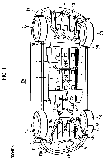
FIG. 1 is a bottom view of a front portion of a vehicle body according to a first embodiment of the present invention;
FIG. 2 is a perspective view of the front portion of the vehicle body according to the first embodiment of the invention, as viewed downward and to the front;
FIG. 3 is a perspective view showing a relationship between the front portion of the vehicle body of FIG. 2 and a sub-frame;
FIG. 4 is a cutaway perspective view of part of a side-sill-side extension of FIG. 2;
FIG. 5 is an enlarged view of a bifurcating portion where a side frame extension of FIG. 1 bifurcates into a side-sill-side extension and a tunnel-side extension;
FIG. 6 is a cross-sectional view taken along line 6-6 of FIG. 1;
FIG. 7 is a cross-sectional view taken along line 7-7 of FIG. 1;
FIG. 8 is a cross-sectional view taken along line 8-8 of FIG. 1;
FIG. 9 is a cross-sectional view of the side frame extension of FIG. 1;
FIG. 10 is a cross-sectional view of the side-sill-side extension of FIG. 1;
FIG. 11 is a cross-sectional view of the tunnel-side extension of FIG. 1;
FIG. 12 is a bottom view of a front portion of a vehicle body according to a second embodiment of the present invention;
FIG. 13 is a bottom view diagrammatically showing the front portion of the vehicle body of FIG. 12;
FIG. 14 is a bottom view of a vehicle body according to a third embodiment of the present invention;
FIG. 15 is a perspective view of the vehicle body according to the third embodiment of the present invention, as viewed from above;
FIG. 16 is a bottom view diagrammatically showing the front portion of the vehicle body of FIG. 14;
FIG. 17 is a bottom view of a front portion of a vehicle body according to a fourth embodiment of the present invention;
FIG. 18 is a perspective view of the front portion of the vehicle body according to the fourth embodiment of the present invention, as viewed from above;
FIG. 19 is a perspective view showing the left half of the front portion of the vehicle body of FIG. 18;
FIG. 20 illustrates the functioning of the left half of the front portion of the vehicle body shown in FIG. 19;
FIG. 21 is a cross-sectional view taken along line 21-21 of FIG. 17;
FIG. 22 is a cross-sectional view of a side sill of the vehicle body according to the fourth embodiment of the present invention;
FIG. 23 is a cross-sectional view taken along line 23-23 of FIG. 22;
FIG. 24 is a cross-sectional view taken along line 24-24 of FIG. 22;
FIG. 25 is a cross-sectional view taken along line 25-25 of FIG. 19;
FIG. 26 is a bottom view diagrammatically showing the front portion of the vehicle body of FIG. 17;
FIG. 27 diagrammatically shows the bottom of a front portion of a vehicle body according to a fifth embodiment of the present invention;
FIG. 28 is a bottom view of a front portion of a vehicle body according to a sixth embodiment of the present invention;
FIG. 29 is a perspective view of the front portion of the vehicle body according to the sixth embodiment of the present invention, as viewed downward and to the front;
FIG. 30 is a cross-sectional view taken along line 30-30 of FIG. 28;
FIG. 31 is a cross-sectional view taken along line 31-31 of FIG. 28;
FIG. 32 is a cross-sectional view taken along line 32-32 of FIG. 28;
FIG. 33 is a cross-sectional view taken along line 33-33 of FIG. 28;
FIG. 34 is a cross-sectional view taken along line 34-34 of FIG. 28;
FIG. 35 is a bottom view diagrammatically showing the front portion of the vehicle body of FIG. 28;
FIG. 36 is a cross-sectional view of a tunnel portion of a vehicle body according to a seventh embodiment of the present invention;
FIG. 37 is a cross-sectional view of a tunnel portion of a vehicle body according to an eighth embodiment of the present invention;
FIG. 38 is a cross-sectional view of a tunnel portion of a vehicle body according to a ninth embodiment of the present invention;
FIG. 39 is a bottom view of a front portion of a vehicle body according to a tenth embodiment of the present invention;
FIG. 40 is a perspective view of the front portion of the vehicle body according to the tenth embodiment of the present invention, as viewed downward and to the front;
FIG. 41 is a cross-sectional view taken along line 41-41 of FIG. 39;
FIG. 42 is a cross-sectional view taken along line 42-42 of FIG. 39;
FIG. 43 is a cross-sectional view taken along line 43-43 of FIG. 39;
FIG. 44 is a bottom view diagrammatically showing the front portion of the vehicle body of FIG. 39;
FIG. 45 is a bottom view of a front portion of a vehicle body according to an eleventh embodiment of the present invention;
FIG. 46 is a perspective view of the front portion of the vehicle body according to the eleventh embodiment of the present invention, as viewed upward and rearward;
FIG. 47 is a cross-sectional view taken along line 47-47 of FIG. 45;
FIG. 48 is a bottom view of a front portion of a vehicle body according to a twelfth embodiment of the present invention;
FIG. 49 is a perspective view of the front portion of the vehicle body according to the twelfth embodiment of the present invention, as viewed upward and rearward;
FIG. 50 is a cross-sectional view taken along line 50-50 of FIG. 48;
FIG. 51 is a cross-sectional view taken along line 51-51 of FIG. 48;
FIG. 52 is a cross-sectional view taken along line 52-52 of FIG. 48;
FIG. 53 is a bottom view diagrammatically showing the front portion of the vehicle body of FIG. 48;
FIG. 54 is a bottom view of a front portion of a vehicle body according to a thirteenth embodiment of the present invention;
FIG. 55 is a cross-sectional view taken along line 55-55 of FIG. 54; and
FIG. 56 is a schematic view illustrating a front portion of a conventional vehicle body.
Certain embodiments of the present invention will be described below with reference to the accompanying drawings.
First Embodiment
A vehicle body structure according to a first embodiment is described with reference to FIGS. 1 to 11. A vehicle 10 in the first embodiment is a passenger vehicle, and a vehicle body 11 accommodates an engine compartment 12 formed in a front portion and a passenger compartment 13 located immediately behind the engine compartment 12, as shown in FIGS. 1 and 2. The vehicle 10 has a fuel tank 21 incorporated in a front-half portion of the vehicle body 11.
The vehicle body 11 is formed of a unitary body and bilaterally symmetric with respect to a vehicle-width direction center line CL passing through the widthwise center of the vehicle 10 and extending in the vehicle's longitudinal direction. The front-half portion of the vehicle body 11 accommodates a dashboard 15, left and right front side frames 16, 16, left and right side sills 17, 17, a tunnel portion 18, a floor panel 19, left and right side frame extensions 22, 22, left and right connecting members 26, 26, left and right tunnel frames 27, 27, and a rear cross-member 29.
The dashboard 15 is a partition that is positioned behind the left and right front side frames 16, 16; partitions the vehicle body 11 into front and rear portions, that is, divides the vehicle body 11 into the front engine compartment 12 and the rear passenger compartment 13, and has a rough L shape in a side view, as shown in FIGS. 2 and 6. Specifically, the dashboard 15 is obtained by integrating a vertical plate 30 that divides the vehicle body 11 into the engine compartment 12 and the passenger compartment 13, an inclined plate 31 extending rearward and downward from the lower end of the vertical plate 30, and a horizontal plate 32 extending rearward from the rear end of the inclined plate 31.
The description continues in the full USPTO document.
About 6,630 words. The USPTO PDF has it with every drawing.
Fees are due 3.5, 7.5 and 11.5 years after grant. This patent expired on March 11, 2026, so the fee marked "not paid" was the one that went unpaid.
VEHICLE BODY STRUCTURE
Filed Oct 2010 · published Aug 2012Vehicle body structure
Filed Oct 2010 · granted Mar 2014Earlier publications, parents and continuations. None of them can still be enforced, or this patent would not be listed.
Prior art cited by the examiner or applicant. Useful when you check your own idea for novelty.
Everything on this page comes from the documents linked above.