Background of the invention
1. Field of the invention
The present invention relates to an image quality stabilization method executed by an image forming apparatus.
2. Description of the related art
Recently, an electrophotographic image forming apparatus and an inkjet image forming apparatus have been widely used. It is desired by the market that an image forming apparatus of this type be capable of printing an image at a sufficiently high quality.
As one of the causes of image degradation, density unevenness, which may occur in the sheet conveyance direction (sub scanning direction), may occur during image forming. In order to prevent density unevenness in the sub scanning direction, Japanese Patent Application Laid-Open No. 2007-108246 discusses the following method.
More specifically, the method discussed in Japanese Patent Application Laid-Open No. 2007-108246 previously measures the level of density unevenness in the sub scanning direction that occurs according to the cycle of an outer periphery of a photosensitive member (photosensitive drum) in association with the phase of the photosensitive member. Furthermore, the method discussed in Japanese Patent Application Laid-Open No. 2007-108246 stores the result of the measurement on a storage unit in a density pattern information table.
Then, information about density unevenness, which has been associated with the phase of the photosensitive member during image forming, is read from the density pattern information table. If a high density is acquired, the method discussed in Japanese Patent Application Laid-Open No. 2007-108246 lowers the image forming density. In other words, Japanese Patent Application Laid-Open No. 2007-108246 discusses reverse density correction control.
To describe the above-described phenomenon of density unevenness in more detail, the variation of a rotation speed of the photosensitive member may be one of the specific causes of density unevenness in the sub scanning direction. To paraphrase this, if the rotation speed of the photosensitive member is low, the position of an electrostatic latent image formed on the photosensitive member may shift in the rotational direction of the photosensitive member (in the upstream direction of the image). Accordingly, the interval between static image lines may decrease.
On the other hand, if the rotation speed of the photosensitive member is high, the electrostatic latent image is displaced in a direction reverse to the rotational direction of the photosensitive member (in the downstream direction of the image). Accordingly, in this case, the interval between static image lines may increase.
Furthermore, if the rotation speed of the photosensitive member is low when the toner adhered to the electrostatic latent image forming position is primarily transferred from the photosensitive member to an intermediate transfer member, then the position of the image after the primary transfer shifts in a reverse direction of the rotational direction of the photosensitive member (i.e., in the downstream direction of the image). Accordingly, in this case, the interval between static image lines may increase.
On the other hand, if the rotation speed of the photosensitive member is high, the position of the image after the transfer shifts in the rotation direction of the photosensitive member (in the upstream direction of the image). Accordingly, the interval between line images may decrease.
As described above, an electrostatic latent image and an image may be displaced due to the variation of the rotation speed of the photosensitive member. Accordingly, the density of the image formed on the intermediate transfer member may become uneven. To macroscopically observe an image having an uneven density, the density of a region in which the image has been highly densely formed may appear to be high. On the other hand, the density of another region in which the image has been loosely formed may appear to be low. As a result, an observer of the image may recognize that density unevenness has occurred on the image.
As described above, in order to primarily prevent density unevenness, Japanese Patent Application Laid-Open No. 2007-108246 discusses a method for correcting the uneven density by reverse density correction.
However, the density correction method cannot solve the very problem of uneven intervals between line images. To paraphrase this, it is desired by the market to introduce a method for more directly solving the problem of unevenly formed line images.
Summary of the invention
According to an aspect of the present invention, an image forming apparatus which includes a rotatable photosensitive member, a light emission unit configured to emit a laser beam to the photosensitive member based on image information, and a transfer unit configured to transfer a toner image developed on the photosensitive member by the laser beam emitted by the light emission unit onto a member to be transferred, includes an acquisition unit configured to acquire variable speed information, which indicates a variable rotation speed of the photosensitive member, and an image position correction unit configured to correct an image position according to the variable rotation speed based on the variable speed information that has been acquired by the acquisition unit by executing image processing on the image information.
According to an aspect of the present invention, the problem of unevenly formed line images can be more directly solved.
Further features and aspects of the present invention will become apparent from the following detailed description of exemplary embodiments with reference to the attached drawings.
Brief description of the drawings
The accompanying drawings, which are incorporated in and constitute a part of the specification, illustrate exemplary embodiments, features, and aspects of the invention and, together with the description, serve to explain the principles of the present invention.
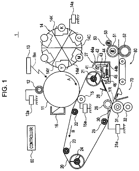
FIG. 1 is a cross section of a color image forming apparatus according to an exemplary embodiment of the present invention.
FIGS. 2A and 2B illustrate an example of an optical performance detection sensor.
FIG. 3 illustrates exemplary functional blocks of the image forming apparatus.
FIG. 4 is a flow chart illustrating exemplary image position correction parameter determination processing.
FIG. 5A is a timing chart of a signal output from a rotary encoder. FIG. 5B illustrates an example of a variation of a photosensitive member surface speed with time. FIG. 5C illustrates an example of a variation of the photosensitive member surface speed with time for each rotation cycle.
FIG. 6 illustrates a correspondence relation between a variation with time of the surface speed of a photosensitive member and a processing content.
FIG. 7 illustrates an example of a series of operations from exposure processing to primary transfer processing.
FIGS. 8A through 8D illustrate a deviation of an interval between line images from an ideal interval after the primary transfer.
FIG. 9 is a flow chart illustrating an example of image position correction processing.
FIGS. 10A through 10C illustrate a method for correcting the position of an image by image processing.
FIG. 11 is a flow chart of a series of processing executed by the image forming apparatus during image forming.
FIG. 12 illustrates an example of an effect by the image position correction processing.
FIG. 13 illustrates exemplary functional blocks of the image forming apparatus.
FIG. 14 is a flow chart illustrating an example of phase difference detection processing.
FIGS. 15A through 15C illustrate a phase difference detection method.
FIGS. 16A and 16B illustrate a phase difference detection method.
FIG. 17 illustrates exemplary functional blocks of the image forming apparatus.
FIGS. 18A through 18E illustrate an exemplary hardware configuration of a motor.
FIGS. 19A and 19B illustrate an example of processing for detecting the rotation speed of the motor.
Description of the embodiments
Various exemplary embodiments, features, and aspects of the invention will be described in detail below with reference to the drawings.
An image forming apparatus according to an exemplary embodiment of the present invention, which can solve density unevenness of an image to be formed by correcting the very displacement of an image to prevent density unevenness, will be described in detail below with reference to the attached drawings. Components, units, portions, methods, or the like are mere examples of the present invention. In other words, the following exemplary embodiment of the present invention can be appropriately altered or modified within the scope of the present invention.
FIG. 1 is a cross section of a color image forming apparatus according to a first exemplary embodiment of the present invention.
Referring to FIG. 1, the color image forming apparatus forms an electrostatic latent image by using exposure light (a laser beam) emitted based on image information, which is supplied from an image processing apparatus (not illustrated in FIG. 1). Furthermore, the color image forming apparatus forms a single-color toner image by developing the electrostatic latent image.
In addition, the color image forming apparatus forms single-color toner images of each color and transfers the toner images to a transfer material 20 in a mutually overlapping state. Then the multicolor toner image is fixed on the transfer material 20. The color image forming method will be described in detail below.
A paper feed unit 21 feeds the transfer material 20. Photosensitive drums (photosensitive members) 22Y, 22M, 22C, and 22K include an aluminum cylinder coated with an organic photoconductive layer at the outer peripheral thereof. A drive force from a single drive motor 115 (FIG. 3) (not illustrated in FIG. 1), is transmitted to the photosensitive members 22Y, 22M, 22C, and 22K via a gear provided on a shaft of the drive motor 115 or via other gears. Accordingly, each of the photosensitive members 22Y, 22M, 22C, and 22K is rotated by the drive motor 115.
In the present exemplary embodiment, a single drive motor 115 drives the photosensitive members 22Y, 22M, 22C, and 22K. However, alternatively, a motor that drives each photosensitive member can be used.
An injection charging device charges the photosensitive member. Four injection charging devices 23Y, 23M, 23C, and 23K correspond to four colors of yellow (Y), magenta (M), cyan (C), and black (K), respectively. A sleeve 23YS, 23MS, 23CS and 23KS is provided to each injection charging device as described in FIG. 1 by a circle.
Exposure light (a laser beam) is emitted by a laser diode provided to scanner units 24Y, 24M, 24C, and 24K. The surface of the photosensitive members 22Y, 22M, 22C, and 22K is selectively exposed by the exposure light. An electrostatic latent image is formed at a position on the surface of the photosensitive member irradiated with the laser beam.
The photosensitive members 22Y through 22K rotate with a specific decentration component. However, at a timing of forming the electrostatic latent image, the phase of each photosensitive member 22 has already been adjusted to exert the same decentration effect at a transfer unit.
Each development unit 26 develops and visualizes the electrostatic latent image by using a recording agent (i.e., a toner), which is supplied by each toner cartridge (25Y, 25M, 25C, 25K). Four development units 26Y, 26M, 26C, and 26K correspond to four colors of yellow (Y), magenta (M), cyan (C), and black (K), respectively. Each sleeve 26YS, 26MS, 26CS and 26KS is provided to each development unit. Each development unit is detachably provided onto the photosensitive member 22.
An intermediate transfer member 27, which contacts the photosensitive members 22Y, 22M, 22C, and 22K, is driven and rotated by an intermediate transfer member drive roller 216 in the clockwise direction during color image forming. The intermediate transfer member 27 rotates in synchronization with the rotation of the photosensitive members 22Y, 22M, 22C, and 22K to transfer each single-color toner image on the intermediate transfer member 27.
The intermediate transfer member 27 functions as a member to be transferred. Subsequently, a transfer roller 28, which will be described below, comes in contact with the intermediate transfer member 27 to convey the transfer material 20 by being sandwiched between the transfer roller 28 and the intermediate transfer member 27. In this manner, the multicolor toner image on the intermediate transfer member 27 is transferred onto the transfer material 20.
While the multicolor toner image is transferred on the transfer material 20, the transfer roller 28 contacts the transfer material 20 at a position 28a. After printing is completed, the transfer roller 28 moves to a position 28b to separate from the transfer material 20.
A fixing device 210 fixes the transferred multicolor toner image on the transfer material 20 by fusing while the transfer material 20 is conveyed. In the example illustrated in FIG. 1, the fixing device 210 includes a fixing roller 211, which applies heat to the transfer material 20. In addition, the fixing device 210 includes a pressure roller 212, which applies pressure to the transfer material 20 to press-contact the transfer material 20 against the fixing roller 211. The fixing roller 211 and the pressure roller 212 have a hollow structure. The fixing roller 211 includes a built-in heater 213 inside. Similarly, the pressure roller 212 includes a built-in heater 214 inside.
The transfer material 20 having the multicolor toner image transferred thereon is further conveyed by the fixing roller 211 and the pressure roller 212. Then, the transfer material 20 is subjected to heat and pressure applied by the fixing roller 211 and the pressure roller 212, respectively, to fix the toner images on the surface of the transfer material 20.
After the toner images are fixed thereon, the transfer material 20 is discharged by a discharge roller (not illustrated) onto a paper discharge tray (not illustrated). Then the image forming operation ends.
A cleaning unit 29 cleans up the toner that remains on the intermediate transfer member (member to be transferred) 27. Waste toners that remain after four-color multicolor toner images are transferred from the intermediate transfer member 27 onto the transfer material 20 are collected into a cleaner container.
A density sensor (hereinafter may also be referred to as an "optical performance detection sensor") 215 is provided within the image forming apparatus illustrated in FIG. 1 to face the intermediate transfer member 27. The density sensor 215 measures the density of a toner patch formed on the surface of the intermediate transfer member 27.
In the example illustrated in FIG. 1, the color image forming apparatus includes the intermediate transfer member 27. However, alternatively, an exemplary embodiment of the present invention can be implemented by an image forming apparatus that employs a primary transfer method, by which a toner image developed on a photosensitive member 22 is directly transferred onto the transfer material. If the alternative configuration is employed, the present invention can be implemented by substituting the intermediate transfer member 27 in the following description with a transfer material conveyance belt (transfer material carrying member).
In addition, in the following description, a direction perpendicular to a main scanning direction for scanning an image when viewed from above is referred to as a "conveyance direction" (a sub scanning direction). In other words, a direction of conveying the transfer material and the rotation direction of the intermediate transfer member may be referred to as the conveyance direction (the sub scanning direction).
An example of the density sensor 215, which is the optical performance detection sensor, will be described below with reference to FIGS. 2A and 2B.
Referring to FIG. 2A, the density sensor 215 is constituted by a light-emitting diode (LED) 8, which is alight emission element, and a phototransistor 10, which is a light-sensitive element. Light emitted from the LED 8 reaches the surface of the intermediate transfer member 27 via a slit 9, which suppresses diffused light. By restricting irregular reflection light by an aperture 11, regular reflection components of the light are received by the light-sensitive element 10.
FIG. 2B illustrates an exemplary circuitry configuration of the density sensor 215. Referring to FIG. 2B, a resistor 12 and the light-sensitive element 10 divide a voltage Vcc. A resistor 13 restricts a current for driving the LED 8. A transistor 14 toggles the LED 8 on and off according to a signal from a central processing unit (CPU).
In the circuit illustrated in FIG. 2B, if the amount of regular reflection light from the toner image when the light is emitted by the LED 8 is large, the current that flows into the light-sensitive element 10 increases. As a result, a value of a voltage V1, which is detected as an output, becomes large.
More specifically, in the circuitry configuration illustrated in FIG. 2B, if the density of the toner patch is low and the amount of the regular reflection light is large, the detected voltage V1 becomes high. On the other hand, if the density of the toner patch is high and the amount of the regular reflection light is small, the detected voltage V1 becomes low. The density value can be calculated based on the detected voltage.
Now, functions provided to suppress the level of density unevenness will be described in detail below with reference to FIG. 3. The following various processing is executed to each color of Y, M, C, and K. More specifically, the same processing is executed to each of the different colors of Y, M, C, and K. Accordingly, in the following description, processing for the color component Y only will be described with reference to FIG. 3. In the following description, units, portions, or components similar to those described above with reference to FIG. 1 are provided with the same reference numerals and symbols. Accordingly, the detailed description thereof will not be repeated here.
Referring to FIG. 3, an image forming apparatus 101 includes the following processing units, each of which being constituted by an application specific integrated circuit (ASIC), a CPU, or a combination thereof.
The image forming apparatus 101 includes a laser printer engine 102. Image data is serially input from an external apparatus (not illustrated), such as a computer apparatus, a controller, or a document reading apparatus, to a halftone processing unit 103 in order of rasterization. More specifically, in the present exemplary embodiment, image data corresponding to the color Y, of the CMYK color space represented in the unit of 8 bits, is input. The actual image processing is executed based on the above-described image data.
The halftone processing unit 103 generates gray-scale image data by using a publicly known pseudo gray-scale representation method, such as multivalued dithering. The halftone processing unit 103 outputs the generated image data to a bitmap prememory 104. The bitmap prememory 104 includes a page memory that temporarily stores raster image data that has been subjected to halftone processing and stores image data of one page. Alternatively, any band memory capable of storing data of a plurality of lines can be also used as the bitmap prememory 104. For easier understanding, in the present exemplary embodiment, it is supposed that the bitmap prememory 104 has a capacity large enough for storing image data of one page.
An image position correction processing unit 105 executes image position correction processing, which will be described below. In addition, the image position correction processing unit 105 serially outputs the corrected image data to a bitmap postmemory 111 in order of rasterization thereof. The bitmap postmemory 111 includes a page memory for temporarily storing the raster image data that has been subjected to the image position correction processing and for image data of one page. Similarly to the bitmap prememory 104, any band memory that stores data of a plurality of lines can be used as the bitmap postmemory 111.
For easier understanding, in the present exemplary embodiment, it is supposed that the bitmap postmemory 111 has a capacity large enough to store image data of one page.
A pulse width modulation (PWM) processing unit 106 reads the image data from the bitmap postmemory 111. In addition, the PWM processing unit 106 generates a signal for driving the scanner unit 24Y.
The image forming apparatus 101, which executes exposure scanning (scanning by laser beam) by using the scanner unit 24Y, is capable of controlling the exposure amount based on a publicly known PWM signal. The scanner unit 24Y emits light from a laser diode and exposes the surface of the photosensitive member 22Y to form an electrostatic latent image.
A speed measurement unit 107 detects the rotation speed of the photosensitive member 22Y. In addition, the speed measurement unit 107 outputs the detected rotation speed to a parameter setting processing unit 108 where necessary. A nonvolatile storage unit 109 is constituted by a rewritable non-volatile memory, such as a flash memory. The nonvolatile storage unit 109 stores an apparatus body parameter, which is necessary for executing processing in the flowchart of FIG. 4. The nonvolatile storage unit 109 notifies the apparatus body parameter to the parameter setting processing unit 108.
The apparatus body parameter is a phase difference .DELTA.t between a surface speed of the photosensitive member 22Y when the scanner unit 24Y irradiates the photosensitive member 22Y with the laser beam and a surface speed of the photosensitive member 22Y when the toner image formed by the laser beam onto the photosensitive member 22Y is primarily transferred onto the intermediate transfer member 27. The phase difference .DELTA.t will be described below. The laser beam is not directly emitted from the scanner unit 24Y onto the photosensitive member 22Y. In other words, the photosensitive member 22Y is irradiated with the laser beam indirectly via various lenses or reflection mirrors.
An engine control unit 110 controls an operation of each component related to the image forming described above with reference to FIG. 1. More specifically, the engine control unit 110 controls various devices provided within the engine 102, such as the paper feed unit 21, the drive motor 115, the injection charging device 23Y, the development device 26Y, the intermediate transfer member 27, the transfer roller 28, the fixing unit 210, and the scanner unit 24Y.
In addition, the engine control unit 110 notifies exposure executable time tp to the parameter setting processing unit 108. More specifically, the engine control unit 110 notifies the exposure executable time tp for each page to the parameter setting processing unit 108. When the exposure executable time tp comes, the engine control unit 110 transmits an exposure start signal to the PWM processing unit 106.
The engine control unit 110 outputs the exposure executable time tp after each unit included in the laser printer engine 102 has become ready for image forming and the exposure scanning has become available after image data of a page to be exposed is input to the bitmap postmemory 111.
If a calculation for each line image, which will be described in detail below with reference to FIGS. 4 and 9, is completed sufficiently faster than the speed of exposure of each line image, image data of only a specific number of lines can be input to the bitmap postmemory 111 before the notification of the exposure executable time tp.
The exposure executable time tp is a timing for permitting the exposure in synchronization with the position of a printable region in a conveyance path. More specifically, if the scanning with the laser beam emitted by the scanner unit 24Y is to be executed on all printable regions, the exposure executable time tp is equivalent to a timing of first scanning by the scanner unit 24Y with the laser beam.
Accordingly, if image data corresponding to an edge of a printable region is not to be subjected to the scanning with the laser beam in an actual operation, the exposure by the scanner unit 24Y is not to be executed at the exposure executable time tp. Furthermore, in the present exemplary embodiment, the exposure executable time tp is also referred to as a "laser beam emission executable timing", which is a timing at which the emission of light (irradiation on the photosensitive member 22Y with light) by the scanner unit 24Y can be executed.
FIG. 4 is a flowchart illustrating exemplary image position correction parameter determination processing according to the present exemplary embodiment. The image position correction parameter determination processing will be described in detail below with reference to the flowchart of FIG. 4.
The flowchart of FIG. 4 illustrates processing for calculating the amount of displacement of each line image, which is primarily transferred onto the intermediate transfer member 27, from an ideal position in the sub scanning direction in relation to the variable rotation speed of the photosensitive member. Image processing (image position correction) illustrated in the flowchart of FIG. 9, which will be explained below, is executed according to a parameter of the displacement amount of each line image calculated by the processing illustrated in the flowchart of FIG. 4.
Referring to FIG. 4, in step S401, the parameter setting processing unit 108 starts image position correction parameter determination processing. In step S402, the speed measurement unit 107 measures the rotation speed of the photosensitive member 22Y. More specifically, the speed measurement unit 107 measures the rotation speed, which can sequentially vary.
For the speed measurement unit 107, a publicly known rotary encoder, which is attached to the rotation shaft of the photosensitive member 22Y, can be applied. Now, an exemplary method for measuring the rotation speed of the photosensitive member 22Y executed by the speed measurement unit 107, which is a rotary encoder, will be described below.
Referring to FIG. 5A, an encoder pulse signal 7011 is output from the rotary encoder. An encoder pulse signal is used for detecting the rotation speed of a rotational member to be measured. The rotary encoder outputs a square wave of 1 pulse as the rotational member rotates by a predetermined phase. More specifically, if a rotary encoder which outputs a square wave of p pulses for one rotation of the rotational member is used, the rotary encoder outputs a square wave of 1 pulse as the rotational member rotates by the cycle of 1/p.
In the following description, it is supposed that the surface speed Vdo(t) 702 of the photosensitive member 22Y from a timing t0 is measured. In this case, the speed measurement unit 107 measures time dt0 required for 1 pulse of the encoder pulse signal 7011, which has been output at the timing t0.
Subsequently, by using the following mathematical expression (1), the speed measurement unit 107 calculates the surface speed Vdo(t0) of the photosensitive member 22Y at the moment at which the required time dt0 is measured. The surface speed Vdo(t0) in the following mathematical expression
is superposed with a plurality of frequency components. Vdo(t0)=(.pi..times.R)/(p.times.dt0)
where "R" denotes a diameter of the photosensitive member 22Y. For example, if the required time dt0 is measured in the unit of a second, Vdo(t0) is equivalent to the surface speed of the photosensitive member 22Y per one second.
In addition, similarly to the calculation of the required time dt0, the speed measurement unit 107 sequentially calculates times dt01, dt02, dt03, dt04, dt05 and the like required for 1 pulse. Furthermore, by executing the calculation similar to that by the mathematical expression (1), the speed measurement unit 107 measures the rotational member surface speed Vdo(t).
FIG. 5B illustrates an example of a surface speed Vdo(t) 703, which is the surface speed of the photosensitive member 22Y during a time period from a timing t0 to a timing tn. Referring to FIG. 5B, the rotation speed of the photosensitive member 22Y shows fluctuation from a target surface speed Vtd.
A waveform includes cyclic speed variations (various speed components) combined therein.
The unevenness of the rotation speed, i.e., the surface speed, (the variation of speed) of the photosensitive member 22Y may be caused primarily due to unevenness of the rotation speed of the photosensitive member 22Y of the rotation cycle Td per one rotation of the photosensitive member 22Y, or due to unevenness of the rotation speed of the motor 115, which drives the photosensitive member 22Y, of the rotation cycle Tm per one rotation of the motor 115.
In some cases, the uneven speed may be caused due to decentration of a gear 116, which transmits the rotational force from the motor 115. In the following description, focusing on the rotation cycle Td per one rotation of the photosensitive member 22Y and the rotation cycle Tm per one rotation of the motor 115, a method for suppressing density unevenness that may be caused due to Td and Tm will be described.
Density unevenness that may occur due to any cause other than the uneven speed, which is caused due to the decentration of the gear 116, can also be suppressed by a method similar to the method described in the present exemplary embodiment.
In step S403, the parameter setting processing unit 108 acquires variable speed information, which includes a measurement result, from the speed measurement unit 107. Furthermore, the parameter setting processing unit 108 executes a calculation for predicting the rotation speed of the photosensitive member 22Y at an arbitrary subsequent timing based on the surface speed Vdo(t) of the photosensitive member 22Y.
In the present exemplary embodiment, the speed information refers to information about the rotation speed of the rotational member, whose rotation speed is to be measured. However, alternatively, various information other than the rotation speed can be used as the speed information. More specifically, because the variation of the speed of a rotational member corresponds to the phase of the variation of the speed of the rotational member, the phase of the variation of the speed of the rotational member can be used as the speed information. In addition, because the speed of a rotational member may constantly vary in response to the position of rotation of the rotational member, positional information about the rotational member, which indirectly indicates the rotation speed of the rotational member, can be used as the speed information.
The parameter setting processing unit 108 extracts speed unevenness Vdf(t) of the rotation cycle Td per one rotation of the photosensitive member 22Y based on the surface speed Vdo(t) of the photosensitive member 22Y. Furthermore, the parameter setting processing unit 108 calculates an amplitude Ad of the speed unevenness Vdf(t) and an initial phase .phi.dt0 of the speed unevenness at a timing t0. The speed unevenness amplitude Ad and the initial phase .phi.dt0 can be calculated by executing, for example, a well-known fast Fourier transform (FFT) calculation on the surface speed Vdo(t) of the photosensitive member 22Y.
In FIG. 5C, an example of a variable speed Vdf(t) 704, which has been extracted by the parameter setting processing unit 108, is illustrated. In the similar manner, the parameter setting processing unit 108 extracts a speed unevenness Vmf(t) of the rotation cycle Tm per one rotation of the motor 115. Furthermore, the parameter setting processing unit 108 calculates the an amplitude Am of the speed unevenness Vmf(t) and an initial phase .phi.mt0 of the speed unevenness at a timing t0. In FIG. 5C, an example of a variable speed Vmf(t) 705, which has been extracted by the parameter setting processing unit 108, is illustrated.
By using the following mathematical expression (2), the speed Vd(t) of the photosensitive member 22Y at an arbitrary time t, which is calculated based on the cycles Td and Tm, can be calculated: Vd(t)=Vtd+Ad.times.cos(.omega.d.times.t-.phi.dt0)+Am.times.cos(.omega.m.t- imes.t-.phi.mt0)
where each of terms .omega.d and .omega.m can be calculated as follows: .omega.d=2.pi./Td .omega.m=2.pi./Tm.
In the mathematical expression (2), the term Vd(t) expresses that the uneven rotation speed of the rotation cycle Td per one rotation of the photosensitive member 22Y and the uneven rotation speed of the rotation cycle Tm per one rotation of the motor 115 are superposed with regard to the target surface speed Vtd.
When the cycles Td and Tm are focused, which are calculated by the calculation, the speed Vd(t) of the photosensitive member 22Y at an arbitrary time t is equivalent to a speed 801 illustrated in FIG. 6. The parameter setting processing unit 108 executes the calculation for the speed Vd(t) for all pages of the print job.
FIG. 6 illustrates what processing is to be executed according to the variation of the speed Vd(t) of the photosensitive member 22Y in response to the variation with time. The image position correction parameter determination processing and the image processing for a second page and thereafter are executed in parallel to the image forming of a first page. More specifically, FIG. 6 schematically illustrates an exemplary order of the processing. As illustrated in FIG. 6, the time taken for actual image forming is longer than the total of time required for two types of the processing executed previous thereto. The time t in FIG. 6 is timing information, which can be represented by a timer count value.
In step S404, the engine control unit 110 determines the exposure executable time tp. The determined exposure executable time tp is notified to the parameter setting processing unit 108. In addition, the engine control unit 110 determines the exposure executable time tp for each page. The determined exposure executable time tp for each page is notified to the parameter setting processing unit 108.
The exposure executable time tp can be defined as time of the following timing. The exposure executable time tp is a time at which the exposure of an image can be predicted to be executed after each component of the laser printer engine 102 has become ready for image forming, the processing in the flowchart of FIGS. 4 and 9 have been completed, and image data of the image has been input to the bitmap postmemory 111.
If a calculation for each line image, which will be described in detail below with reference to FIGS. 4 and 9, is completed sufficiently faster than the speed of exposure of each line image, image data of only a specific number of lines can be input to the bitmap postmemory 111 before the notification of the exposure executable time tp.
In step S405, the parameter setting processing unit 108 calculates the surface speed Ve(t) of the photosensitive member 22Y during the exposure. The surface speed Vd(t) of the photosensitive member 22Y can be directly used as Ve(t). Accordingly, the surface speed Ve(t) of the photosensitive member 22Y when the exposure is executed at the time t can be expressed by the following mathematical expression (3). Ve(t)=Vd(t) (3).
In step S406, the parameter setting processing unit 108 predicts (calculates) the surface speed Vt (t) of the photosensitive member 22Y when the image exposed at the time t is primarily transferred. At the position of the latent image on the photosensitive member 22Y, which has been exposed based on image information, the latent image is developed by the development unit 26Y. Then the developed image is primarily transferred to the intermediate transfer member 27, as illustrated in FIG. 7.
The latent image exposed by the scanner unit 24Y at an exposure point 701 is conveyed to the position of the development unit 26Y. The latent image is subjected to the development by using the toner at the development unit 26Y. The developed toner image is conveyed to a primary transfer point 702. Then the toner image is primarily transferred onto the intermediate transfer member 27.
As described above, it takes a specific length of time to primarily transfer an image after exposure. Furthermore, for an image exposed at the time t, a specific phase difference .DELTA.t (time difference) may arise on the speed of the photosensitive member 22Y when the image is primarily transferred. The specific phase difference .DELTA.t is determined according to the distance, which is indicated as Ld in FIG. 7, between the exposure point 701 and the primary transfer point 702 and according to an average surface speed of the photosensitive member 22Y. The specific phase difference .DELTA.t can be expressed as follows: .DELTA.t=2.pi..times.(mod(Ld/Vtd,Td))/Td.
The target surface speed Vtd is used for the average surface speed of the photosensitive member 22Y. The nonvolatile storage unit 109 stores the phase difference .DELTA.t. In addition, the nonvolatile storage unit 109 notifies the information expressed as the phase difference .DELTA.t to the parameter setting processing unit 108 where necessary.
Because the position of the exposure point 701 may vary due to the affect from an error of an installation position of the scanner unit 24Y, different apparatuses may have different values of the phase difference .DELTA.t. Therefore, it is necessary to measure the phase difference .DELTA.t (time difference) of each apparatus during the manufacture of the apparatus and to store the measured phase difference .DELTA.t in the nonvolatile storage unit 109.
For example, during the manufacture of an image forming apparatus, the speed measurement unit 107 is temporarily provided around the primary transfer point 702 (FIG. 7) to measure the rotation speed (the surface speed Vt(t)) of the photosensitive member 22Y at the time of image transfer. Alternatively, the rotation speed of the photosensitive member 22Y at the time of image transfer can be measured according to a result of detection by two sensors, which can be provided across the photosensitive member 22Y in the direction of rotation thereof and which has a function similar to the function of the speed measurement unit 107.
As described above, the present exemplary embodiment is intended to various methods for measuring the phase difference between the speed Vd (t) achieved when the laser beam is emitted from the scanner unit 24Y and the rotation speed of the photosensitive member 22Y achieved when the toner image developed is transferred during the manufacture of the apparatus.
With the notified phase difference .DELTA.t, the parameter setting processing unit 108 calculates the surface speed Vt(t) of the photosensitive member 22Y when the image exposed at the time t is primarily transferred, by using the following mathematical expression (4). As expressed by the mathematical expression (4), the phase difference may arise for each cycle of the speed unevenness. Vt(t)=Vtd+Ad.times.cos(.omega.d.times.t-.phi.dt0+.DELTA.td)+Am.times.cos(- .omega.m.times.t-.phi.mt0.times..DELTA.tm)
where ".DELTA.td" denotes the phase difference of the speed unevenness of the rotation cycle Td per one rotation of the photosensitive member 22Y, ".DELTA.tm" denotes the phase difference of the speed unevenness of the rotation cycle Tm per one rotation of the motor 115, the term "phase difference .DELTA.t" collectively denotes the phase differences, and the phase difference .DELTA.t={.DELTA.td, .DELTA.tm}.
In step S407, the parameter setting processing unit 108 calculates the interval between the lines of the electrostatic latent image.
The description continues in the full USPTO document.
 Lapsed, fee not paid1 drawing