Background of the invention
(a) Field of the Invention
The present invention relates to a method of reducing pulsation or changes in brightness of an electric energy-driven luminous body resulting from the pulsation rate of an alternating current power voltage, by using polyphase-drive electric energy to reduce the pulsations.
(b) Description of the Prior Art
The deficiency of traditional alternating current lamps lies in their discontinuous optical pulsation caused by alternating current power pulsation.
Summary of the invention
The present invention relies on polyphase alternating current power or direct current power rectified from polyphase alternating current power to drive a common electric energy-driven luminous body; or to separately drive proximately installed individual electric energy-driven luminous bodies, so as to reduce alternating current-induced pulsation of the light output of the luminous body or bodies is reduced.
Brief description of the drawings
FIG. 1 are waveform diagrams of a traditional single phase alternating current power or alternating current full wave-rectified direct current directly driving an electric energy-driven luminous body.
FIG. 2 is a circuit diagram of an electric energy-driven luminous body individually driven by single phase power in three ways through an inductor split-phase current, a capacitor split-phase current, and a resultant vector current of inductor and capacitor split-phase currents.
FIG. 3 is a circuit diagram showing interchanging positions of a capacitor and/or inductor with respect to the electric energy-driven luminous body of FIG. 2.
FIG. 4 is a diagram showing brightness variations of an electric energy-driven luminous body in FIG. 2 and FIG. 3.
FIG. 5 is a circuit block diagram of the present invention in which impedances and electric energy-driven luminous bodies are connected in parallel with the alternating current power source in three ways: a capacitor is in series with an electric energy-driven luminous body, an inductor is in series with an electric energy-driven luminous body, and a resistor is in series with a electric energy-driven luminous body.
FIG. 6 is a circuit block diagram showing a capacitor in series with an electric energy-driven luminous body and connected in parallel directly with the electric energy-driven luminous body and another electric energy-driven luminous body in series with a resistor in order to accept alternating current or bidirectional power drive.
FIG. 7 is a circuit block diagram showing an inductor in series with an electric energy-driven luminous body and connected in parallel directly with the electric energy-driven luminous body or with the electric energy-driven luminous body in series with the resistor in order to accept alternating current or bidirectional power drive.
FIG. 8 is a circuit block diagram showing a capacitor in series with an electric energy-driven luminous body and connected in parallel with the electric energy-driven luminous body in series with the inductor in order to accept alternating current or bidirectional power drive.
FIG. 9 is a circuit diagram of an embodiment of the present invention in which three-phase, four wire alternating current power is drives three sets of electric energy-driven luminous bodies in Y connection.
FIG. 10 is a circuit diagram of an embodiment of the present invention in which three-phase alternating current power drives three sets of electric energy-driven luminous bodies in .DELTA. connection.
FIG. 11 is a first circuit diagram of an embodiment of the present invention in which three-phase alternating current power drives two sets of electric energy-driven luminous bodies in V connection.
FIG. 12 is a second circuit diagram of an embodiment of the present invention in which three-phase alternating current power drives two sets of electric energy-driven luminous bodies in V connection.
FIG. 13 is a circuit diagram showing three-phase alternating current power being supplied, through current limiting devices, to a three phase full wave direct current electric energy that had been rectified by a bridge rectifier and then supplied to a direct current electric energy-driven luminous body.
FIG. 14 is a circuit diagram showing three-phase alternating current power passing through a half-wave current-limiting impedance device to a three-phase half-wave rectifier, the rectified direct current electric energy being delivered to a direct current electric energy-driven luminous body.
FIG. 15 is a circuit diagram of a capacitor and inductor effecting split phase and then full wave rectification on single phase power in order to drive a direct current electric energy-driven luminous body.
FIG. 16 is a circuit diagram of a capacitor and resistor effecting split phase and then full wave rectification on the single phase power in order to drive the direct current electric energy-driven luminous body.
FIG. 17 is a circuit diagram of an inductor and resistor effecting split phase and then full wave rectification on single-phase power in order to drive a direct current electric energy-driven luminous body.
FIG. 18 is a circuit diagram of an inductor, resistor and capacitor effecting split phase and then full wave rectification on a single-phase power in order to drive a direct current electric energy-driven luminous body.
FIG. 19 is a circuit diagram of an inductor and resistor effecting split phase and then half wave rectification on single-phase power in order to drive a direct current electric energy-driven luminous body.
Description of main component symbols
(103): Electric energy-driven luminous body (1000): Inductive impedance devices
(3012): Conductive terminals (2000): Direct current electric energy-driven luminous body (201): Capacitor (3000): Three-phase bridge rectifier (301): Inductor (3500): Three-phase half wave rectifier (401): Resistor
(704): Rectifier diodes
(804): Single phase bridge rectifiers a: Alternating Current power wave form b: Wave-form of direct current rectified from alternating current c: Optical pulsation wave form of electric energy-driven luminous body (I101) (I102) (I103): Current N: Neutral line R S T: Three-phase alternating current power lines (Z10): Current limiting device (Z11): Half wave current limiting impedance device
Detailed description of the preferred embodiments
The deficiency of traditional alternating current lamps lies in their discontinuous pulsating light output caused by alternating current power pulsation.
The present invention relies on polyphase alternating current power with phase difference or direct current power rectified from polyphase alternating current power to drive a common electric energy-driven luminous body; or to separately drive proximately installed individual electric energy-driven luminous bodies, so that pulsation of the light output by the luminous body or bodies is reduced.
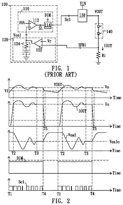
FIG. 1 is a waveform diagram of the optical pulsation resulting from use of traditional single phase alternating current power or full wave-rectified direct current to directly drive an electric energy-driven luminous body.
As shown in FIG. 1: a is an alternating current power wave-form; b is a wave-form of direct current rectified from alternating current; c is an optical pulsation wave-form of an electric energy-driven luminous body. If the electric energy input is a bidirectional pulsating electric energy with a bidirectional non-sinusoidal wave, the result is the same.
FIG. 2 is a circuit diagram of an electric energy-driven luminous body individually driven by single phase power in three ways through inductor split-phase current, capacitor split-phase current or the resultant vector current of inductor and capacitor split-phase currents.
As shown in FIG. 2, the components of the preferred circuit are arranged as follows:
The terminals (1011), (1021), and
of the electric energy-driven luminous bodies (101),
and
driven by bidirectional electric energy are connected together. Terminal
of the electric energy-driven luminous body
is connected to terminal
of capacitor (201). Terminal
of electric energy-driven luminous body
is connected to terminal
of the inductor (301). Terminal
of the capacitor
is connected to terminal
of the inductor (301), and then to a terminal of an alternating current or bidirectional electric energy source. Terminal
of electric energy-driven luminous body
is connected to the other terminal of the alternating current or bidirectional electric energy source, such that the current (I101) that passes through electric energy-driven luminous body
is the vector sum of the current (I102) that passes through electric energy-driven luminous body
and the current (I103) of electric energy-driven luminous body (103), which is also the total current.
Electric energy-driven luminous bodies (101), (102),
may take the form of three luminous bodies integrated into one body or three proximately installed bodies consisting of gas bulbs with filaments, solid state electric energy luminous bodies such as LEDs, and other luminous bodies that accept electric energy drive.
FIG. 3 is a circuit diagram showing interchanging positions of capacitor
with respect to electric energy-driven luminous body
and/or inductor
with respect to electric energy-driven luminous body
in FIG. 2, wherein:
Terminal
of electric energy-driven luminous body (101), terminal
of capacitor
and terminal
of inductor
are connected together. The other terminal
of capacitor
is connected to terminal
of electric energy-driven luminous body (102). The other terminal
of the inductor
is connected to terminal
of the electric energy-driven luminous body (103). The other terminal
of electric energy-driven luminous body
is connected to terminal
of the electric energy-driven luminous body (103), and then to a terminal of a power source. The other terminal
of the electric energy-driven luminous body
is connected to the other terminal of the power source;
Electric energy-driven luminous bodies (101), (102),
may include three luminous bodies integrated into one body or three proximately installed bodies consisting of gas bulbs with filaments, solid state electric energy luminous bodies such as LEDs, and other luminous bodies that accept electric energy drive;
Moreover, if series capacitor
or one of the electric energy-driven luminous bodies of inductor
is directly connected in parallel with electric energy-driven luminous body (101), or in parallel with the electric energy-driven luminous body
of the series resistor, then the pulsation of the projected light energy is also improved.
FIG. 4 is a diagram of the brightness of the electric energy-driven luminous bodies in FIG. 2 and FIG. 3, showing a significant reduction in their luminous pulsation.
FIG. 5 is a circuit block diagram of an embodiment of the present invention, wherein the alternating current power is in parallel with: the capacitor
in series with the electric energy-driven luminous body (102), the inductor
in series with the electric energy-driven luminous body (103), and the resistor
in series with the electric energy-driven luminous body (101).
FIG. 6 is a circuit block diagram of an embodiment of the present invention showing a capacitor
in series with the electric energy-driven luminous body
and connected in parallel directly with the electric energy-driven luminous body (101), or with the electric energy-driven luminous body
in series with the resistor (401), in order to accept alternating current or bidirectional power drive.
FIG. 7 is a circuit block diagram of an embodiment of the present invention showing an inductor
in series with the electric energy-driven luminous body
and connected in parallel directly with the electric energy-driven luminous body (101), or with the electric energy-driven luminous body
in series with the resistor (401), in order to accept alternating current or bidirectional power drive.
FIG. 8 is a circuit block diagram of the present invention showing a capacitor
in series with the electric energy-driven luminous body
and connected in parallel with the electric energy-driven luminous body
in series with the inductor (301), in order to accept alternating current or bidirectional power drive.
The lighting device with pulsation suppression by polyphase-driven electric energy may employ three-phase alternating current power to supply electricity to the electric energy-driven luminous body to minimize the pulsation of the luminous brightness.
FIG. 9 is a circuit diagram of the present invention wherein three-phase, four wire alternating current power drives three sets of electric energy-driven luminous bodies in Y connection, using the following circuit arrangement:
Electric energy-driven luminous body
is directly connected or in series with the resistive and/or capacitive and/or inductive impedance device (1000), after which one terminal connects to a three-phase power line R, while the other terminal goes to a common Y connection point.
Electric energy-driven luminous body
is directly connected or in series with the resistive and/or capacitive and/or inductive impedance device
after which one terminal connects to a three-phase power line S-, while the other terminal goes to a common Y connection point.
Electric energy-driven luminous body
is directly connected or in series with the resistive and/or capacitive and/or inductive impedance device (1000), after which one terminal connects to a three-phase power line T-, while the other terminal goes to a common Y connection point.
FIG. 10 is a circuit diagram of the present invention wherein three-phase alternating current power drives three sets of electric energy-driven luminous bodies in .DELTA. connection. As shown in FIG. 10, this circuit is arranged as follows:
Electric energy-driven luminous body
is directly connected or in series with the resistive and/or capacitive and/or inductive impedance device (1000), and then in parallel between power line R and power line S.
Electric energy-driven luminous body
is directly connected or in series with the resistive and/or capacitive and/or inductive impedance device (1000), and then in parallel between power line S and power line T.
Electric energy-driven luminous body
is directly connected or in series with the resistive and/or capacitive and/or inductive impedance device (1000), and then in parallel between power line T and power line R.
FIG. 11 is a first circuit diagram of an embodiment of the present invention in which three-phase alternating current power is used to drive two sets of electric energy-driven luminous bodies in V connection, as follows:
Electric energy-driven luminous body
is directly connected or in series with the resistive and/or capacitive and/or inductive impedance device (1000), and then in parallel between power line R and power line S.
Electric energy-driven luminous body
is directly connected or in series with the resistive and/or capacitive and/or inductive impedance device (1000), and then in parallel between power line S and power line T.
FIG. 12 is a second circuit diagram of the embodiment of the present invention in which three-phase alternating current power drives two sets of electric energy-driven luminous bodies in V connection, as follows:
Electric energy-driven luminous body
is connected in series with electric energy-driven luminous body (102), and then in parallel between power line R and power line T;
The power line S, after connecting in series with a resistive and/or capacitive and/or inductive impedance device (1000), is then connected to the series connection point of electric energy-driven luminous body
and electric energy-driven luminous body (102).
The lighting device with optical pulsation suppression by polyphase-driven electric energy further may rely on direct current power rectified from polyphase alternating current power to drive a common electric energy-driven luminous body; or to separately drive proximately installed individual electric energy-driven luminous bodies so that the pulsation of the outwardly projected light is reduced.
FIG. 13 is a circuit diagram showing three-phase alternating current power supplied, through the current limit device (Z10), from a three-phase full wave direct current electric energy source that is rectified by a bridge rectifier so as to supply direct current electric energy-driven luminous body (2000).
As shown in FIG. 13, this circuit is arranged as follows:
The input terminals for three-phase alternating current power, -R, S, and T, of the three-phase bridge rectifier
are separately connected in series with the current limiting impedance device (Z10) and then connected to the three-phase alternating current power source. Current limiting device (Z10) includes resistor
and/or inductor
and/or capacitor (201). The direct current electric energy from the direct current output terminal is supplied to the direct current electric energy-driven luminous body (2000).
Electric energy-driven luminous body
may include gas bulbs with filaments, solid state electric energy luminous bodies such as an LED, and other luminous bodies that accept direct current electric energy drive.
FIG. 14 is a circuit diagram showing three-phase alternating current power passing through a half-wave current limiting impedance device (Z11) to a three phase half-wave rectifier (3500), with the rectified direct current electric energy being supplied to the direct current electric energy-driven luminous body (2000).
As shown in FIG. 14, this circuit is arranged as follows:
The input terminals for three-phase alternating current power, -R, S, and T, of the three-phase half wave rectifier
are separately connected in series with the half wave current limiting impedance device (Z11) and then connected to the three-phase alternating current power source. Half wave current limiting impedance device (Z11) may include resistor
and/or inductor
and/or capacitor (201). The direct current electric energy from the direct current output terminal of the three-phase half wave rectifier
is supplied to the direct current electric energy-driven luminous body (2000), while the negative terminal of the direct current electric energy-driven luminous body connects to the neutral line N of the three-phase, four wire power source.
Direct current electric energy-driven luminous body
may include one or more gas bulbs with filaments, solid state electric energy luminous bodies such as LEDs, and other luminous bodies that accept direct current electric energy drive;
Moreover, single phase alternating current power may be used from at least two of the following:
output electric energy from the series connection between the single alternating current power and resistor (401),
output electric energy from the series connection between the same single phase alternating current power and capacitor (201), and
electric energy from the series connection between the same alternating current power and the inductor (301). After being rectified by separate rectifiers, the single phase power from at least two of the above arrangements may be used to jointly drive the direct current electric energy-driven luminous body
in order to reduce pulsation of the light output of the luminous body (2000).
FIG. 15 is a circuit diagram of a capacitor and inductor effecting split phase and then full wave rectification on single phase power in order to drive a direct current electric energy-driven luminous body (2000).
As shown in FIG. 15, one terminal of the single phase alternating current power supply is connected to one of the alternating current input terminals of the single phase bridge rectifier
through capacitor (201). The same terminal from the same single phase alternating current power is also connected to one of the alternating current input terminals of another single phase bridge rectifier
through inductor (301). The other terminal of the single phase alternating current power supplies the other alternating current power input terminal of the single phase bridge rectifiers
and (803); and then the direct current output terminals of the single phase bridge rectifiers
and
are connected in parallel with the same polarity in order to drive the direct current electric energy-driven luminous body (2000).
FIG. 16 is a circuit diagram of a capacitor and resistor effecting split phase and then full wave rectification on single phase power in order to drive a direct current electric energy-driven luminous body (2000).
As shown in FIG. 16, one terminal of the single phase alternating current power is connected to one of the alternating current input terminals of the single phase bridge rectifier
through capacitor (201). The same terminal from the same single phase alternating current power is connected to one of the alternating current input terminals of another single phase bridge rectifier
through resistor (401). The other terminal of the single phase alternating current power supplies the other alternating current power input terminal of the single phase bridge rectifiers
and (804), and then the direct current output terminals of the single phase bridge rectifiers
and
are connected in parallel with a same polarity in order to drive the direct current electric energy-driven luminous body (2000).
FIG. 17 is a circuit diagram of the inductor and resistor effecting split phase and then full wave rectification on single phase power in order to drive the direct current electric energy-driven luminous body (2000).
As shown in FIG. 17, one terminal of the single phase alternating current power is connected to one of the alternating current input terminals of the single phase bridge rectifier
through inductor (301). The same terminal from the same single phase alternating current power is connected to one of the alternating current input terminals of another single phase bridge rectifier
through resistor (401). The other terminal of the single phase alternating current power supplies the other alternating current power input terminal of the single phase bridge rectifiers
and (804). Then, the direct current output terminals of the single phase bridge rectifiers
and
are connected in parallel with a same polarity in order to drive the direct current electric energy-driven luminous body (2000).
FIG. 18 is an circuit diagram of the inductor, resistor and capacitor effecting split phase and then full wave rectification on the single phase power in order to drive a direct current electric energy-driven luminous body (2000).
As shown in FIG. 18, one terminal of the single phase alternating current power is connected to one of the alternating current input terminals of the single phase bridge rectifier
through inductor (301). The same terminal from the same single phase alternating current power is connected to one of the alternating current input terminals of another single phase bridge rectifier
through resistor (401). The same terminal of the same single phase alternating current power is connected to one of the alternating input terminals of another single phase bridge rectifier
through capacitor (201). The other terminal of the single phase alternating current power supplies the other alternating current power input terminal of the single phase bridge rectifiers (802),
and (804); and then the direct current output terminals of the single phase bridge rectifiers (802),
and
are connected in parallel with a same polarity in order to drive the direct current electric energy-driven luminous body (2000).
FIG. 19 is a circuit diagram of an inductor and resistor effecting split phase and then half wave rectification on the single phase power in order to drive a direct current electric energy-driven luminous body (2000).
As shown in FIG. 19, one terminal of the single phase alternating current power is connected to the alternating current input terminals of the rectifier diode
through inductor (301). The same terminal from the same single phase alternating current power is connected to one of the alternating current input terminals of another rectifier diode
through resistor (401). The other terminal of the single phase alternating current power is connected to the negative terminal of the direct current electric energy-driven luminous body (2000). Then, the direct current output positive terminals of the rectifier diodes
and
are connected in parallel with a same polarity in order to drive the direct current electric energy-driven luminous body (2000).
 Lapsed, fee not paid5 drawings