 Lapsed, fee not paid8 drawings
Vehicles & Drones · US 8,662,230 B2
Saddle-type vehicle
A cowl structure that is small in size and light, and that is effective in preventing air discharged from a radiator from being applied to the legs of the rider.
US 8,662,232 B2 · Assignee: Honda Motors Co., Ltd. · Inventors: Nakamura; Masanori et al.
Sheet 1 of 20 from the published document. All sheets in the USPTO PDF
In an electric two-wheeled motor vehicle including: an electric motor for generating power to drive a rear wheel; a battery for supplying electric power to the electric motor; a rider seat on which a rider seats; a housing box disposed below the rider seat; and a side cover covering the housing box below the rider seat, the electric two-wheeled motor vehicle configured to allow charging of the battery, an opening (118) covered with an openable and closeable lid member (120) is provided in the side cover (48), and a power-receiving-side connector (67) to which a power-supplying-side connector leading to an external power source can be inserted and connected is fixed and disposed between an outer surface of the side cover (48) and the housing box to face the opening (118). Accordingly, it is possible to eliminate the requirement for a rider seat to be opened in charging of a battery and thereby facilitate the charging work.
Among electric scooters which travel by driving a rear wheel by using a drive force generated by an electric motor, an electric scooter in which a battery for supplying electric power to the electric motor can be charged with a charger is already known from Patent Document 1.
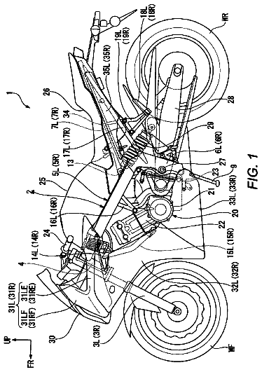
1 of 20 drawing sheets so far from the published document, cropped to the drawing. Every sheet is in the USPTO PDF.
What the patent claimed, word for word. All of it is now free to use.
The present invention relates to an electric two-wheeled motor vehicle including: an electric motor for generating power to drive a rear wheel; a battery for supplying electric power to the electric motor; a rider seat on which a rider seats; a housing box disposed below the rider seat; and a side cover covering the housing box below the rider seat, the electric two-wheeled motor vehicle configured to allow charging of the battery.
Among electric scooters which travel by driving a rear wheel by using a drive force generated by an electric motor, an electric scooter in which a battery for supplying electric power to the electric motor can be charged with a charger is already known from Patent Document 1.
Patent Document
Patent Document 1: Japanese Patent No. 3336529
Problems to be Solved by the Invention
In the above-described electric scooter disclosed in Patent Document 1, the charger connected to the battery is disposed below a storage box, and a power-receiving-side connection terminal connected to the charger is provided in a front portion of the storage box. When a work of charging from an external power source is to be performed, a rider seat above the storage box needs to be opened. Thus, not only the charging work is cumbersome, but also the rider seat needs to be left open in a charging state and there is a desire for a configuration allowing the charging work to be performed with the rider seat closed.
The present invention is made in view of the circumstances described above, and an object thereof is to provide an electric two-wheeled motor vehicle which eliminates the requirement for a rider seat to be opened in charging of a battery and thereby facilitates the charging work.
Means for Solving the Problems
In order to attain the above object, according to a first aspect of the present invention, there is provided an electric two-wheeled motor vehicle including: an electric motor for generating power to drive a rear wheel; a battery for supplying electric power to the electric motor; a rider seat on which a rider seats; a housing box disposed below the rider seat; and a side cover covering the housing box below the rider seat, the electric two-wheeled motor vehicle configured to allow charging of the battery, characterized in that an opening covered with an openable and closeable lid member is provided in the side cover, a power-receiving-side connector to which a power-supplying-side connector leading to an external power source is capable of being inserted and connected is fixed and disposed between an outer surface of the side cover and an outer surface of a side wall of the housing box to face the opening, and an insertion-connection direction of the power-supplying-side connector to the power-receiving-side connector is set to be inclined inward in a vehicle width direction toward the power-receiving-side connector from front or rear of the power-receiving-side connector. Further, according to a second aspect of the present invention, there is provided an electric two-wheeled motor vehicle including: an electric motor for generating power to drive a rear wheel; a battery for supplying electric power to the electric motor; a rider seat on which a rider seats; a housing box disposed below the rider seat; and a side over covering the housing box below the rider seat, the electric two-wheeled motor vehicle configured to allow charging of the battery, characterized in that an opening covered with an openable and closeable lid member is provided in the side cover, a power-receiving-side connector to which a power-supplying-side connector leading to an external power source is capable of being inserted and connected is fixed and disposed between an outer surface of the side cover and an outer surface of a side wall of the housing box to face the opening, and a housing recess portion for housing and disposing her in at least part of the power-receiving-side connector is formed in part of the outer surface of the side wall of the housing box to be recessed inward. Further, according to a third aspect of the present invention, there is provided an electric two-wheeled motor vehicle including: an electric motor for generating power to drive a rear wheel; a battery for supplying electric power to the electric motor; a rider seat on which a rider seats; a housing box disposed below the rider seat; and a side cover covering the housing box below the rider seat, the electric two-wheeled motor vehicle configured to allow charging of the battery, characterized in that an opening covered with an openable and closeable lid member is provided in the side cover, a stay having an attachment portion is fixed to a frame member disposed on a lateral side of the housing box and forming part of a vehicle-body frame, the attachment portion extending inward from the frame member, and a power-receiving-side connector to which a power-supplying-side connector leading to an external power source is capable of being inserted and connected is disposed between an outer surface of the side cover and an outer surface of a side wall of the housing box to face the opening, and is attached to the attachment portion. Further, according to a fourth aspect of the present invention, there is provided an electric two-wheeled motor vehicle including: an electric motor for generating power to drive a rear wheel; a battery for supplying electric power to the electric motor; a rider seat on which a rider seats; a housing box disposed below the rider seat; and a side cover covering the housing box below the rider seat, the electric two-wheeled motor vehicle configured to allow charging of the battery, characterized in that an opening covered with an openable and closeable lid member is provided in the side cover, a power-receiving-side connector to which a power-supplying-side connector leading to an external power source is capable of being inserted and connected is fixed and disposed between en outer surface of the side cover and an outer surface of a side will of the housing box face the opening, the lid member is turnably supported by the side cover via a hinge mechanism, and a closed state maintaining mechanism is provided between the lid member and the side cover, the closed state maintaining mechanism switching between a lock state where the lid member is maintained at a closed position in a non-operation state of an operator disposed to face a surface of the side cover at a position near the opening and an unlock state where an opening operation of the lid member is allowed in accordance with an operation of the operator.
Furthermore, according to a fifth aspect of the present invention, in addition to the configuration of any one of the second to fourth aspects, an insertion-connection direction of the power-supplying-side connector to the power-receiving-side connector is set to be inclined inward in a vehicle width direction toward the power-receiving-side connector from front or rear of the power-receiving-side connector.
According to a sixth aspect of the present invention, in addition to the configuration of the first or fifth aspect, there is provided the electric two-wheeled motor vehicle further comprising a main stand configured to turn forward from a housed position to a standing position, wherein the insertion-connection direction of the power-supplying-side connector insertable and connectable to the power-receiving-side connector from the front is set to be inclined inward in the vehicle width direction toward the power-receiving-side connector from the front.
According to a seventh aspect of the present invention, in addition to any one of the configurations of the first to third, fifth and sixth aspects, the lid member is supported by the side cover such that the lid member is set to an open position by being operated rearward in a front-rear direction of a vehicle, and a turning axis of the lid member is set to be inclined upward toward the rear.
According to an eighth aspect of the present invention, in addition to any one of the configurations of the first to seventh aspects, a recess portion recessed inward from an outer side surface of the side cover is formed in the side cover to be closable by the lid member, and the opening is provided in the recess portion.
According to a ninth aspect of the present invention, in addition to any one of the configurations of the first and third to eighth aspects, a housing recess portion for housing and disposing therein at least part of the power-receiving-side connector is formed in part of the outer surface of the side wall of the housing box to be recessed inward.
According to a tenth aspect of the present invention, in addition to any one of the configurations of the first, second and fourth to ninth aspects, a stay having an attachment portion is fixed to a frame member disposed on a lateral side of the housing box and forming part of a vehicle-body frame, the attachment portion extending inward from the frame member, and the power-receiving-side connector is attached to the attachment portion.
According to an eleventh aspect of the present invention, in addition to any one of the configurations of the first to tenth aspects, there is provided the electric two-wheeled motor vehicle further comprising a side stand for maintaining a standing state in which a vehicle body is inclined to one side in a vehicle width direction, wherein the power-receiving-side connector and the opening are disposed on a lateral side of the housing box on a side in the vehicle width direction where the side stand is disposed.
According to a twelfth aspect of the present invention, in addition to any one of the configurations of the first to eleventh aspects, the power-receiving-side connector to which the power-supplying-side connector leading to the external power source via a charger is connectable is connected to the battery via a DC-DC converter disposed rearward of the housing box.
According to a thirteenth aspect of the present invention, in addition to any one of the configurations of the first to third aspects, the lid member capable of covering the opening is turnably supported by the side cover via a hinge mechanism, and a closed state maintaining mechanism is provided between the lid member and the side cover, the closed state maintaining mechanism switching between a lock state where the lid member is maintained at a closed position in a non-operation state of an operator disposed to face a surface of the side cover at a position near the opening and an unlock state where an opening operation of the lid member is allowed in accordance with an operation of the operator.
According to a fourteenth aspect of the present invention, in addition to the configuration of the fourth or thirteenth aspect, the lid member is formed to have a substantially triangular shape having three vertex portions, the closed state maintaining mechanism is provided between the lid member and the side cover, in a certain vertex portion among the vertex portions, and the lid member is turnably supported by the side cover via the hinge mechanism on a side portion of the side cover on the opposite side to the certain vertex portion.
According to a fifteenth aspect of the present invention, in addition to the configuration of the fourteenth aspect, the lid member is turnably supported by the side cover such that the lid member is in a posture with one vertex portion among the vertex portions being directed downward in a state where the opening is closed.
According to a sixteenth aspect of the present invention, in addition to any one of the configurations of the fourth and thirteenth to fifteenth aspects, a conductive wire leading to the power-supplying-side connector is interposed between the lid member in a closed state and the side cover with an elastic member interposed between the conductive wire and at least one of the lid member and the side cover.
According to a seventeenth aspect of the present invention, in addition to any one of the configurations of the fourth and thirteenth to sixteenth aspects, there is provided the electric two-wheeled motor vehicle further comprising restriction means for restricting a switching work of the operator of switching the closed state maintaining mechanism from the lock state to the unlock state.
According to an eighteenth aspect of the present invention, in addition to the configuration of the seventeenth aspect, the restriction means includes a switch operator used for switching between a restricted state where the telling of the closed state maintaining mechanism from the lock state to the unlock state is restricted and a non-restricted state where the switching of the closed state maintaining mechanism from rain the lock state to the unlock state is allowed, and the switch operator is disposed in the housing box to be capable of being operated in the housing box.
According to a nineteenth aspect of the present invention, in addition to the configuration of the eighteenth aspect, a portion of the restriction means other than the switch operator is disposed between the housing box and the side cover.
According to a twentieth aspect of the present invention, in addition to the configuration of the eighteenth or nineteenth aspect, the restriction means is configured to mechanically work in accordance with a work of the switch operator being a control knob capable of a turn operation.
Furthermore, according to an 21st aspect of the present invention, in addition to any one of the configurations of the fourth and thirteenth to twentieth aspects, a design mark showing that the power-receiving-side connector is disposed inside the lid member is provided on an external design surface of the lid member.
Here, a rear frame 29 of embodiments corresponds to the frame member of the present invention; a high voltage battery 36 of the embodiments corresponds to the battery of the present invention; a hinge mechanism 107 of the embodiments corresponds to the hinge mechanism of the present invention; an opening 118, 145 of the embodiments correspond to the opening of the present invention; a recess portion 119 of the embodiments corresponds to the recess portion of the present invention; a lid member 120, 146 of the embodiments corresponds to the lid member of the present invention; a push button 152 of the embodiments corresponds to the operator of the present invention; and a control knob 161 of the embodiments corresponds to the switch operator of the present invention.
Effects of the Invention
In accordance with the first to fourth aspects of the present invention, the power-receiving-side connector to which the power-supplying-side connector leading to the external power source is capable of being inserted and connected is fixed and disposed between the outer surface of the side cover and the outer surface of the side wall of the housing box to face the opening provided in the side cover. Thus, opening and closing works of the rider scat covering the housing box from above are not required, and at charging work can be performed with the rider seat closed. Hence, the charging work is made easy, and the usability is improved.
In accordance with the first or fifth aspect of the present invention, the insertion-connection direction of the power-supplying-side connector to the power-receiving-side connector is a direction inclined inward in the vehicle width direction toward the power-receiving-side connector from the front or the rear of the vehicle. Thus, even when the power-receiving-side connector is disposed between the side cover and the housing box, the housing box is secured to have a sufficient capacity.
In accordance with the sixth aspect of the present invention, a force applied to a hinged support of the main stand during the insertion and the connection of the power-supplying-side connector to the power-receiving-side connector is applied in such a direction that the main stand is maintained at a standing position side. Hence, the main stand does not turn undesirably to a housing position side by the insertion and connection of the power-supplying-side connector to the power-receiving-side connector.
In accordance with the seventh aspect of the present invention, the lid member is set to an opened position by being operated rearward about the turning axis inclined upward toward the rear, and the lid member is in a posture inclined downward toward the rear in the opened state. Thus, when the charging is performed with the lid member opened, turning of the lid member to a closing side which is caused by an effect of wind and the like can be avoided as much as possible.
In accordance with the eighth aspect of the present invention, the opening which the power-receiving-side connector faces is provided in the recess portion which is formed in the side cover and which can be closed with the lid member. Thus, as portion where the recess portion is formed functions as a reinforcement rib, and the strength of the side cover can be thereby improved. Furthermore, a portion inward of the side cover is covered with the recess portion except for the opening. Thus, the power-receiving-side connector can be easily found, and also it is less likely to drop small objects into the portion inward of the side cover when the recess portion is opened.
In accordance with the second or ninth aspect of the present invention, at least part of the power-receiving-side connector is housed and disposed in the housing recess portion formed in part of the outer surface of the side wall of the housing box. Thus, only a required portion of the side wall of the housing box is recessed, and the reduction of capacity of the housing box which is caused by disposing the power-receiving-side connector between the side cover and the housing box is suppressed to a small degree.
In accordance with the third or tenth aspect of the present invention, the attachment portion extending inward from the frame member is provided in the stay fixed to the frame member disposed on the lateral side of the housing box, and the power-receiving-side connector is attached to the attachment portion. Thus, the side cover can be easily attached to the frame member without the power-receiving-side connector protruding outward from the frame member.
In accordance with the eleventh aspect of the present in the power-receiving-side connector and the opening are disposed on the lateral side of the housing box on the side where the side stand is disposed, the side stand used to maintain the standing state in which the vehicle body is inclined to one side in the vehicle width direction. This improves workability of charging in a parked state with the side stand standing.
In accordance with the twelfth aspect of the present invention, the power-receiving-side connector to which the power-receiving-side connector leading to the external power source via the charger is connectable is connected to the battery via the DC-DC converter disposed rearward of the housing box. Thus, a reverse flow from the battery to the power-receiving-side connector is less likely to occur.
In accordance with the fourth or thirteenth aspect of the present invention, the closed state maintaining mechanism capable of maintaining the lid member covering the opening at the closed position is switched from the lock state where the lid member is maintained at the closed position to the unlock state where the opening operation of the lid member is allowed, in accordance with the operation of the operator disposed to face the surface of the side cover at the position near the opening. Thus, the disposed position of the operator can be found quickly, and the lid member can be opened to perform the charging work by simply operating the operator. Hence, the charging work can be made simple. Particularly, setting the operator to the unlock state allows the lid member to be readily opened at any time, and the charging can be quickly performed. Moreover, setting the operator to the lock state as needed makes it impossible for a third party to open the lid member. Thus, the state can be selected in accordance with the usage.
In accordance with the fourteenth aspect of the present invention, the closed state maintaining mechanism is provided between the lid member and the side cover, in a certain vertex portion among the three vertex portions of the lid member formed to have the substantially triangular shape, and the lid member is turnably supported by the side cover via the hinge mechanism on the side portion of the side cover on the opposite side to the certain vertex portion. Thus, a gap between the lid member and the side cover which is made by an external force can be made small, and this achieves a tamper-proof function.
In accordance with the fifteenth aspect of the present invention, the lid member having the substantially triangular shape is in such a posture that one vertex portion is directed downward in a state where the opening is closed. Thus, rain water and the like attached to the lid member can be collected to the vertex portion side at a low position and removed.
In accordance with the sixteenth aspect of the present invention, the conductive wire leading to the power-supplying-side connector is interposed between the lid member in the closed state and the side cover with an elastic member interposed between the conductive wire and at least one of the lid member and the side cover. Thus, the charging can be performed with the lid member closed.
In accordance with the seventeenth aspect of the present invention, the switching work of switching the closed state maintaining mechanism from the lock state to the unlock state is restricted by using the restriction means. This is effective when it is desired to restrict the switching work of the operator of switching the closed state maintaining mechanism from the lock state to the unlock state.
In accordance with the eighteenth aspect of the present invention, the switch operator forming part of the restriction means is capable of being operated in the housing box. Thus, the closed state maintaining mechanism can be utilized in a manner suiting the usage of the rider.
In accordance with the nineteenth aspect of the present invention, a portion of the restriction member other than the switch operator is disposed between the housing box and the side cover. Thus, the restriction means is made more compact, and a charging port structure including the restriction means and the closed state maintaining mechanism can be thereby made More compact.
In accordance with the twelfth aspect of the present invention, the switch operator is the control knob, and the restriction means is mechanically configured. Thus, increase in cost is suppressed and a power source causing the restriction means to work is not required.
In accordance with the 21st aspect of the present invention, the design mark showing that the power-receiving-side connector is disposed inside the lid member is provided on the external design surface of the lid member. This allows the position where the power-receiving-side connector is disposed to be found quickly when the charging work is to be performed, and leads to improvement in the efficiency of the charging work.
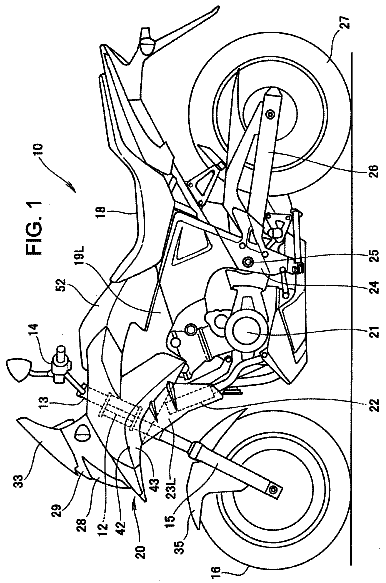
FIG. 1 is a side view of an electric two-wheeled motor vehicle according to a first embodiment. (first embodiment)
FIG. 2 is a side view of the electric two-wheeled motor vehicle with a vehicle body cover being omitted. (first embodiment)
FIG. 3 is a schematic system diagram of an electric system. (first embodiment)
FIG. 4 is a view seen from an arrow 4 in FIG. 2. (first embodiment)
FIG. 5 is a perspective view of a battery box and cooling air introduction ducts. (first embodiment)
FIG. 6 is a sectional view taken along a line 6-6 in FIG. 1 with an under cover being omitted. (first embodiment)
FIG. 7 is an enlarged sectional view taken along a line 7-7 in FIG. 6. (first embodiment)
FIG. 8 is an exploded perspective view of a lea shield and a lid. (first embodiment)
FIG. 9 is a view seen from an arrow 9 in FIG. 2. (first embodiment)
FIG. 10 is an enlarged view of a part indicated by an arrow 10 in FIG. 9. (first embodiment)
FIG. 11 is an enlarged view of an essential part in FIG. 2. (first embodiment)
FIG. 12 is a view seen from an arrow 12 in FIG. 11. (first embodiment)
FIG. 13 is a view seen from an arrow 13 in FIG. 11. (first embodiment)
FIG. 14 is a side view showing a state in which an opening provided in a side cover is opened. (first embodiment)
FIG. 15 is a side view of an electric two-wheeled motor vehicle according to a second embodiment. (second embodiment)
FIG. 16 is a view seen from an arrow 16 in FIG. 15 with a rider seat being omitted. (second embodiment)
FIG. 17 is a sectional view taken along a line 17-17 in FIG. 16. (second embodiment)
FIG. 18 is an enlarged view of an essential part in FIG. 15 in a charging condition with a part of a lid member being omitted. (second embodiment)
FIG. 19 is a view of a housing box seen from a right side with a side cover being omitted. (second embodiment)
FIG. 20 is a plan view showing configurations of a closed state maintaining mechanism and restriction means. (second embodiment)
23 . . . Electric motor 29 . . . Rear frame being a frame member 31 . . . Side stand 34 . . . Main stand 36 . . . High voltage battery being a battery 38 . . . Housing box 38b . . . Housing recess portion 39 . . . Rider seat 48 . . . Side cover 65 . . . Charger 66 . . . Power-supplying-side connector 67 . . . Power-receiving-side connector 68 . . . DC-DC converter 116 . . . Stay 116a . . . Attachment portion 117 . . . Insertion-connection direction 118, 145 . . . Opening 119 . . . Recess portion 120, 146 . . . Lid member 122 . . . Conducting wire 147 . . . Hinge mechanism 150 . . . Design mark 151 . . . Closed state maintaining mechanism 152 . . . Push button being an operator 160 . . . Restriction means 161 . . . Control knob being a switch operator 167 . . . Elastic member B . . . Vehicle body P1, P2, P3 . . . Vertex portion PS . . . External power source WR . . . Rear Wheel
Embodiments of the present invention are explained below by reference to the attached drawings.
First Embodiment
A first embodiment of the present invention will be explained below by reference to FIG. 1 to FIG. 14. At first, in FIG. 1, this electric two-wheeled motor vehicle is a scooter type electric motorcycle having a low floor 44, and is configured such that a rear wheel WR being a drive wheel is rotationally driven by rotational power generated by an electric motor 23 built into a swingarm 22 whose rear potion pivotally supports an axle 21 of the rear wheel WR.
Referring to FIG. 2, a vehicle-body frame F of the electric two-wheeled motor vehicle includes a head pipe 26 which steerably supports a front fork 24 pivotally supporting a front wheel WF and a steering handle 25 connected to an upper portion of the front fork 24, a down frame 27 which extends downward toward the rear from the head pipe 26, a pair of right and left under frames 28 . . . which are connected to a lower portion of the down frame 27 and extend rearward, and a pair of right and left rear frames 29 . . . which are integrally continuous respectively to rear ends of the under frames 28 . . . and extend upward toward the rear.
A side stand 31 for maintaining a standing state in which a vehicle body B is inclined to the left is turnably attached to pivot plates 30 provided respectively in front portions of both of the rear frames 29 . . . of the vehicle-body frame F. In addition, a front portion of the swingarm 22 is swingably supported by the pivot plates 30 via a pivot 32. A rear cushion unit 33 is provided between a rear portion of the left rear frame 29 among both of the rear frames 29 . . . and a rear portion of the swingarm 22. Moreover, a main stand 34 is turnably attached to the front portion of the swingarm 22.
A battery case 37 housing a high voltage battery 36 of, for example, 72 V for supplying electric power to the electric motor 23 is disposed between both of the under frames 28 . . . while being supported by both of the under frames 28 . . . . A housing box 38 disposed above the swingarm 22 in a side view is disposed between both of the rear frames 29 . . . while being supported by both of the rear frames 29 . . . . The housing box 38 is covered with a closeable and openable rider seat 39 from above. Moreover, a battery housing portion 38a that houses a low voltage battery 40 for supplying electric power of low voltage, for example, 12 V to accessories such as a head lamp 51, a tail lamp 52, and a control unit (not illustrated) is formed integral with a rear lower portion of the housing box 38 in such a way as to protrude downward.
The vehicle-body frame F is covered with a vehicle body cover 41 which forms the vehicle body B together with the vehicle-body frame F and is made of a synthetic resin. The vehicle body cover 41 includes a front cover 42 which covers the head pipe 26 from the front, a leg shield 43 which is continuous to the front cover 42 in such a way as to cover the leg portions of the rider sitting on the rider seat 39 from the front, the low floor 44 which is continuous to a lower portion of the leg shield 43 in such a way that the feet of the rider sitting on the ride seat 39 are placed thereon and which covers the battery case 37 from above, a pair of right and left floor side covers 45 . . . suspended from both lateral sides of the low floor 44 in such a way as to cover both of the under frames 28 . . . from both lateral sides, an under cover 46 which connects lower edges of both of the floor side covers 45 . . . , an under-seat-portion front cover 47 which extends upward from an rear end of the low floor 44 in such way as to cover a portion under the rider seat 39 from the front, a pair of right and left side covers 48 . . . which are continuous respectively to both lateral sides of the under-seat-portion front cover 47 in such a way as to cover the portion under the rider seat 39 from both lateral sides, and a rear cover 49 which is continuous to both of the side covers 48 . . . in such a way as to cover the rear wheel WR from above. The battery case 37 is covered with the low floor 44, the floor side covers 45 . . . , the under cover 46, the under-seat-portion front cover 47, and the side covers 48 . . . of the vehicle body cover 41.
The head lamp 51 is disposed at a front end of the front cover 42 while being supported by a front stay 50 fixed to the head pipe 26, and the tail lamp 52 is attached to the rear frames 29 . . . . Moreover, a front fender 53 covering the front wheel WF from above is attached to the front fork 24. A rear fender 54 covering the rear wheel WR from above in a rear oblique direction is provided continuous with the rear cover 49, and a fender 55 covering the rear wheel WR from above in a front oblique direction is attached to the front portion of the swingarm 22. Moreover, a center portion of the steering handle 25 is covered with a handle cover 56, a front carrier 57 disposed frontward of the front cover 42 is supported by the front stay 50. A rear carrier 58 is disposed rearward of the rider seat 39 above the rear cover 49 while being supported by the rear frames 29 . . . .
Referring to FIG. 3, the electric motor 23 is driven by a power drive unit (PDU) 61 including a control unit. The power drive unit 61 is connected to a positive terminal of the high voltage battery 36 via a fuse 62 and a first relay switch 63. A series circuit including a second relay switch 64 and a resistance 76 is connected in parallel to the first relay switch 63. Incidentally, the high voltage battery 36 and the low voltage battery 40 can be charged with a charger 65 which is capable of outputting a high voltage by being connected to an external power source PS, the high voltage being at the same level as that of high voltage battery 36. A power-receiving-side connector 67 to which a power-supplying-side connector 66 leading to the charger 65 connected to the external power source PS can be inserted and connected is provided on the vehicle side. The power-receiving-side connector 67 is connected to a DC-DC converter 68.
The DC-DC converter 68 includes a field effect transistor 69 which is provided in a line L1 of a pair of lines L1, L2 leading to the power-receiving-side connector 67 and a voltage drop circuit part 70 which is connected to both of the lines L1, L2 to drop the voltage from the charger 65 to a low voltage of, for example, 12 V. Both of the lines L1, L2 of the DC-DC converter 68 are connected to the positive terminal of the high voltage battery 36 via a parallel circuit of the first relay switch 63 and the series circuit including the second relay switch 64 and the resistance 76 to supply a charge current of the high voltage to the high voltage battery 36, and are also connected to a negative side terminal of the high voltage battery 36. The voltage drop circuit part 70 is connected to a positive terminal and a negative terminal of the low voltage battery 40.
The control unit included in the power drive unit 61 is connected to the positive terminal of the low voltage battery 40 via a main switch 72, and is also connected to the negative terminal of the low voltage battery 40. Moreover, switching between connection and disconnection of each of the first and second relay switches 63, 64 can be performed by use of a control current outputted from a battery managing unit (BMU) 73 by using electric power supplied from the low voltage battery 40. The battery managing unit 73 is connected to the positive terminal of the low voltage battery 40 via the main switch 72 and a connector 71, and is also connected to the negative terminal of the low voltage battery 40.
When the main switch 72 is turned ON, the battery managing unit 73 first sets the second relay switch 64 to a conductive state to cause an electric current to flow from the high voltage battery 36 to the power drive unit 61 via the second relay switch 64, the resistance 76, and the fuse 62, and thereafter causes the first relay switch 63 to be conductive. This prevents melting and adhering of the first relay switch 63 which are caused by an inrush current to a capacitor provided in the power drive unit 61.
Incidentally, a circuit between the high voltage battery 36 and the power drive unit 61 as well as a circuit between the high voltage battery 36 and the DC-DC converter 68 form a circuit (circuit shown in bold solid lines) 74 of a high power system leading to the high voltage 36. A circuit between the low voltage battery 40 and the power drive unit 61, a circuit between the low voltage battery 40 and the battery managing unit 73, and a circuit between the low voltage battery 40 and the DC-DC converter 68 form a circuit (circuit shown in thin solid lines) 75 of a low power system leading to the low voltage battery 40. The first relay switch 63, the second relay switch 64, the fuse 62 and the resistance 76 are provided in the circuit 74 of the high power system. The connector 71 and the main switch 72 are provided in the circuit 75 of the low power system.
Note that, the first relay switch 63, the second relay switch 64, and the battery managing unit 73 are housed in the battery case 37 housing the high voltage battery 36.
Referring also to FIGS. 4 to 6, the battery case 37 is formed by fastening a lower case 78 having a box shape with an open top and an upper case 79 having a box shape with an open bottom to each other with multiple screw members 80, 80 . . . . Multiple support plates 81, 81 . . . protruding sideward and fixedly provided to upper portions of lateral sides of the lower case 78 are fastened to both of the under frames 28 . . . of the vehicle-body frame F by using bolts 82, 82 . . . and weld nuts 83, 83 . . . welded to the under frames 28 . . . . Thus, the battery case 37 is supported by both of the under frames 28 . . . .
A cross member 84 straddling a substantially center portion of the battery case 37 in a front-rear direction is provided between both of the under frames 28 . . . , and the low floor 44 is supported by the cross member 84. Moreover, a front protection member 85 protecting a front lower portion of the battery case 37 from the front is provided between the front portions of both of the under frames 28 . . . in such a way as to connect a center portion of the front protection member 85 to lower ends of the down frame 27. A rear portion protection member 86 protecting a rear lower portion of the battery case 37 from the rear is provided between rear portions of both of the under frames 28 . . . . Multiple lower protection members 87, 87 . . . extending in the front-rear direction are provided between the front and rear protection members 85, 86 to protect the battery case 37 from below.
Referring also to FIGS. 7 and 8, downstream end portions of a pair of right and left cooling air introduction ducts 88 . . . are connected to a front portion of the lower case 78 of the battery case 37 via connection tubes 77 . . . . Incidentally, the leg shield 43 is supported by being fixed to a stay 103 with a bolt 93, the stay 103 fixedly attached to a rear portion of the head pipe 26. Both of the cooling air introduction ducts 88 . . . having the down frame 27 interposed therebetween from both sides in the leg shield 43 are disposed to extend along the down frame 27. Meanwhile, a pair of right and left suction openings 90, 90 opened toward the rear of the vehicle are provided in the leg shield 43 at positions corresponding to the connection portion of the down frame 27 to the head pipe 26. Upstream end portions of both of the cooling air introduction ducts 88 . . . are connected to the leg shield 43 via connection tubes 89 . . . to communicate with the suction openings 90 . . . , respectively.
Incidentally, a recess portion 91 recessed frontward from a back surface of the leg shield 43 is formed in the leg shield 43, and both of the suction openings 90 . . . are provided in an upper portion of the recess portion 91. Moreover, a first boss 92 is provided integral to the recess portion 91 in a center portion between both of the suction openings 90 . . . in such a way as to protrude rearward.
A lid 94 covering both of the suction openings 90 . . . is attached to the leg shield 43 with multiple screw members 95, 95 . . . . Cylindrical second bosses 96, 96 . . . are provided, in a protruding manner, integral to the recess portion 91 at positions corresponding to respective corners of an imaginary rectangle surrounding both of the suction openings 90 . . . . The lid 94 whose inner surface is to be in contact with the second bosses 96, 96 . . . is fastened to the leg shield 43 by using the screw members 95, 95 . . . inserted through the lid 94 and screwed to the second bosses 96, 96 . . . .
The description continues in the full USPTO document.
About 6,940 words. The USPTO PDF has it with every drawing.
Fees are due 3.5, 7.5 and 11.5 years after grant. This patent expired on March 4, 2026, so the fee marked "not paid" was the one that went unpaid.
ELECTRIC TWO-WHEELED MOTOR VEHICLE
Filed Sep 2010 · published Aug 2012Electric two-wheeled motor vehicle
Filed Sep 2010 · granted Mar 2014Earlier publications, parents and continuations. None of them can still be enforced, or this patent would not be listed.
Prior art cited by the examiner or applicant. Useful when you check your own idea for novelty.
Everything on this page comes from the documents linked above.