Background
A depth map typically comprises a two-dimensional image of an environment that includes depth information relating to the distances to objects within the environment from a particular reference point. The particular reference point may be associated with an image capture device. Each pixel in the two-dimensional image may be associated with a depth value representing a linear distance from the particular reference point. A variety of techniques may be used to generate a depth map such as structured light illumination and time of flight techniques.
Structured light illumination involves projecting a light pattern into an environment, capturing an image of the reflected light pattern, and then determining distance information from the spacings and/or distortions associated with the reflected light pattern relative to the projected light pattern. The light pattern may be projected using light that is invisible to the naked eye (e.g., IR or UV light) and may comprise a single dot, a single line, or a variety of dimensional patterns (e.g., horizontal and vertical lines, or checkerboard patterns). In some cases, several different light patterns may be necessary to generate accurate depth information.
Time of flight techniques may determine distances to objects within an environment by timing how long it takes for light transmitted from a light source to travel to the objects and reflect back to an image sensor. In some cases, a short light pulse (or series of light pulses) may be projected into the environment at a first point in time and reflections associated with the short light pulse may be captured at a second point in time after the first point in time. A time of flight system may adjust the time difference between the first point in time and the second point in time in order to detect objects at a particular distance (or over a range of distances) associated with the time difference.
Summary
Technology is described for improving the image quality of a depth map by detecting and modifying false depth values within the depth map. In some cases, a depth pixel of the depth map is initially assigned a confidence value based on curvature values and localized contrast information. The curvature values may be generated by applying a Laplacian filter or other edge detection filter to the depth pixel and its neighboring pixels. The localized contrast information may be generated by determining a difference between the maximum and minimum depth values associated with the depth pixel and its neighboring pixels. A false depth pixel may be identified by comparing a confidence value associated with the false depth pixel with a particular threshold. The false depth pixel may be updated by assigning a new depth value based on an extrapolation of depth values associated with neighboring pixel locations.
This Summary is provided to introduce a selection of concepts in a simplified form that are further described below in the Detailed Description. This Summary is not intended to identify key features or essential features of the claimed subject matter, nor is it intended to be used as an aid in determining the scope of the claimed subject matter.
Brief description of the drawings
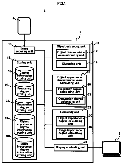
FIG. 1 is a block diagram of one embodiment of a networked computing environment in which the disclosed technology may be practiced.
FIG. 2 depicts one embodiment of a computing system that utilizes one or more depth maps for performing object and/or gesture recognition.
FIG. 3 illustrates one embodiment of computing system including a capture device and computing environment.
FIG. 4A depicts a depth map including one or more near pixels and one or more far pixels.
FIG. 4B depicts a depth profile along a horizontal scan line through the depth map depicted in FIG. 4A.
FIG. 4C depicts a first derivative of the depth profile of FIG. 4B.
FIG. 4D depicts a second derivative of the depth profile of FIG. 4B.
FIG. 5A depicts a 3.times.3 image region including depth pixels z1 through z9.
FIG. 5B depicts one example of a derivative filter for computing a vertical gradient.
FIG. 5C depicts one example of a derivative filter for computing a horizontal gradient.
FIG. 5D depicts one example of a derivative filter for computing a second-order derivative.
FIG. 6A is a flowchart describing one embodiment of a process for identifying and updating false depth pixels in a depth map.
FIG. 6B is a flowchart describing an alternative embodiment of a process for identifying and updating false depth pixels in a depth map.
FIG. 7A is a flowchart describing one embodiment of a process for calculating a plurality of confidence values.
FIG. 7B is a flowchart describing one embodiment of a process for updating one or more false depth pixels.
FIG. 7C is a flowchart describing one embodiment of a process for determining a new depth value given one or more good pixels.
FIG. 8 is a block diagram of an embodiment of a gaming and media system.
FIG. 9 is a block diagram of one embodiment of a mobile device.
FIG. 10 is a block diagram of an embodiment of a computing system environment.
Detailed description
Technology is described for increasing the resolution of a depth map by identifying and updating false depth pixels within the depth map. In some embodiments, a depth pixel of the depth map is initially assigned a confidence value based on curvature values and localized contrast information. The curvature values may be generated by applying a Laplacian filter or other edge detection filter to the depth pixel and its neighboring pixels. The localized contrast information may be generated by determining a difference between the maximum and minimum depth values associated with the depth pixel and its neighboring pixels. A false depth pixel may be identified by comparing a confidence value associated with the false depth pixel with a particular threshold. The false depth pixel may be updated by assigning a new depth value based on an extrapolation of depth values associated with neighboring pixel locations.
One issue involving the generation of depth information using time of flight techniques relates to the inherent trade-off between minimizing noise (i.e., generating higher quality depth maps) and image resolution. In particular, larger pixel sizes may reduce noise by allowing for a greater number of photons to be sensed within a particular period of time. However, the larger pixel sizes come at the expense of reduced image resolution. Thus, there is a need for increasing the resolution of a depth map without sacrificing image quality.
FIG. 1 is a block diagram of one embodiment of a networked computing environment 100 in which the disclosed technology may be practiced. Networked computing environment 100 includes a plurality of computing devices interconnected through one or more networks 180. The one or more networks 180 allow a particular computing device to connect to and communicate with another computing device. The depicted computing devices include mobile device 11, computing environment 12, mobile device 13, and application server 150. In some embodiments, the plurality of computing devices may include other computing devices not shown. In some embodiments, the plurality of computing devices may include more than or less than the number of computing devices shown in FIG. 1. The one or more networks 180 may include a secure network such as an enterprise private network, an unsecure network such as a wireless open network, a local area network (LAN), a wide area network (WAN), and the Internet. Each network of the one or more networks 180 may include hubs, bridges, routers, switches, and wired transmission media such as a wired network or direct-wired connection.
A server, such as application server 150, may allow a client to download information (e.g., text, audio, image, and video files) from the server or to perform a search query related to particular information stored on the server. In general, a "server" may include a hardware device that acts as the host in a client-server relationship or a software process that shares a resource with or performs work for one or more clients. Communication between computing devices in a client-server relationship may be initiated by a client sending a request to the server asking for access to a particular resource or for particular work to be performed. The server may subsequently perform the actions requested and send a response back to the client.
One embodiment of computing environment 12 includes a network interface 145, processor 146, and memory 147, all in communication with each other. Network interface 145 allows computing environment 12 to connect to one or more networks 180. Network interface 145 may include a wireless network interface, a modem, and/or a wired network interface. Processor 146 allows computing environment 12 to execute computer readable instructions stored in memory 147 in order to perform processes discussed herein.
Networked computing environment 100 may provide a cloud computing environment for one or more computing devices. Cloud computing refers to Internet-based computing, wherein shared resources, software, and/or information are provided to one or more computing devices on-demand via the Internet (or other global network). The term "cloud" is used as a metaphor for the Internet, based on the cloud drawings used in computer network diagrams to depict the Internet as an abstraction of the underlying infrastructure it represents.
In some embodiments, computing environment 12 may increase the resolution of a single frame depth image by identifying and updating false depth pixels within the single frame depth image. The false depth pixels may exist for a variety of reasons. For example, a false depth value associated with a false depth pixel may be generated due to several locations in space being integrated into the same pixel location. (i.e., due to resolution limitations). A depth pixel may be considered false if it is associated with a depth value that does not exist within an environment (e.g., it represents an incorrect depth value that is between a foreground object and a background object). The single frame depth image may comprise a depth map.
FIG. 2 depicts one embodiment of a computing system 10 that utilizes one or more depth maps for performing object and/or gesture recognition. The computing system 10 may include a computing environment 12, a capture device 20, and a display 16, all in communication with each other. Computing environment 12 may include one or more processors. Capture device 20 may include one or more color or depth sensing cameras that may be used to visually monitor one or more targets including humans and one or more other real objects within a particular environment. Capture device 20 may also include a microphone. In one example, capture device 20 may include a depth sensing camera and a microphone and computing environment 12 may comprise a gaming console.
In some embodiments, the capture device 20 may include an active illumination depth camera, which may use a variety of techniques in order to generate a depth map of an environment or to otherwise obtain depth information associated the environment including the distances to objects within the environment from a particular reference point. The techniques for generating depth information may include structured light illumination techniques and time of flight (TOF) techniques.
As depicted in FIG. 2, a user interface 19 is displayed on display 16 such that an end user 29 of the computing system 10 may control a computing application running on computing environment 12. The user interface 19 includes images 17 representing user selectable icons. In one embodiment, computing system 10 utilizes one or more depth maps in order to detect a particular gesture being performed by end user 29. In response to detecting the particular gesture, the computing system 10 may execute a new computing application. The particular gesture may include selection of one of the user selectable icons.
FIG. 3 illustrates one embodiment of computing system 10 including a capture device 20 and computing environment 12. In some embodiments, capture device 20 and computing environment 12 may be integrated within a single computing device. The single computing device may be a mobile device, such as mobile device 11 in FIG. 1.
In one embodiment, the capture device 20 may include one or more image sensors for capturing images and videos. An image sensor may comprise a CCD image sensor or a CMOS image sensor. In some embodiments, capture device 20 may include an IR CMOS image sensor. The capture device 20 may also include a depth sensor (or depth sensing camera) configured to capture video with depth information including a depth image that may include depth values via any suitable technique including, for example, time-of-flight, structured light, stereo image, or the like.
The capture device 20 may include an image camera component 32. In one embodiment, the image camera component 32 may include a depth camera that may capture a depth image of a scene. The depth image may include a two-dimensional (2-D) pixel area of the captured scene where each pixel in the 2-D pixel area may represent a depth value such as a distance in, for example, centimeters, millimeters, or the like of an object in the captured scene from the image camera component 32.
The image camera component 32 may include an IR light component 34, a three-dimensional (3-D) camera 36, and an RGB camera 38 that may be used to capture the depth image of a capture area. For example, in time-of-flight analysis, the IR light component 34 of the capture device 20 may emit an infrared light onto the capture area and may then use sensors to detect the backscattered light from the surface of one or more objects in the capture area using, for example, the 3-D camera 36 and/or the RGB camera 38. In some embodiments, pulsed infrared light may be used such that the time between an outgoing light pulse and a corresponding incoming light pulse may be measured and used to determine a physical distance from the capture device 20 to a particular location on the one or more objects in the capture area. Additionally, the phase of the outgoing light wave may be compared to the phase of the incoming light wave to determine a phase shift. The phase shift may then be used to determine a physical distance from the capture device to a particular location associated with the one or more objects.
In another example, the capture device 20 may use structured light to capture depth information. In such an analysis, patterned light (i.e., light displayed as a known pattern such as grid pattern or a stripe pattern) may be projected onto the capture area via, for example, the IR light component 34. Upon striking the surface of one or more objects (or targets) in the capture area, the pattern may become deformed in response. Such a deformation of the pattern may be captured by, for example, the 3-D camera 36 and/or the RGB camera 38 and analyzed to determine a physical distance from the capture device to a particular location on the one or more objects. Capture device 20 may include optics for producing collimated light. In some embodiments, a laser projector may be used to create a structured light pattern. The light projector may include a laser, laser diode, and/or LED.
In some embodiments, two or more different cameras may be incorporated into an integrated capture device. For example, a depth camera and a video camera (e.g., an RGB video camera) may be incorporated into a common capture device. In some embodiments, two or more separate capture devices of the same or differing types may be cooperatively used. For example, a depth camera and a separate video camera may be used, two video cameras may be used, two depth cameras may be used, two RGB cameras may be used, or any combination and number of cameras may be used. In one embodiment, the capture device 20 may include two or more physically separated cameras that may view a capture area from different angles to obtain visual stereo data that may be resolved to generate depth information. Depth may also be determined by capturing images using a plurality of detectors that may be monochromatic, infrared, RGB, or any other type of detector and performing a parallax calculation. Other types of depth image sensors can also be used to create a depth image.
As depicted in FIG. 3, capture device 20 may include one or more microphones 40. Each of the one or more microphones 40 may include a transducer or sensor that may receive and convert sound into an electrical signal. The one or more microphones may comprise a microphone array in which the one or more microphones may be arranged in a predetermined layout.
The capture device 20 may include a processor 42 that may be in operative communication with the image camera component 32. The processor 42 may include a standardized processor, a specialized processor, a microprocessor, or the like. The processor 42 may execute instructions that may include instructions for storing filters or profiles, receiving and analyzing images, determining whether a particular situation has occurred, or any other suitable instructions. It is to be understood that at least some image analysis and/or target analysis and tracking operations may be executed by processors contained within one or more capture devices such as capture device 20.
The capture device 20 may include a memory 44 that may store the instructions that may be executed by the processor 42, images or frames of images captured by the 3-D camera or RGB camera, filters or profiles, or any other suitable information, images, or the like. In one example, the memory 44 may include random access memory (RAM), read only memory (ROM), cache, Flash memory, a hard disk, or any other suitable storage component. As depicted, the memory 44 may be a separate component in communication with the image capture component 32 and the processor 42. In another embodiment, the memory 44 may be integrated into the processor 42 and/or the image capture component 32. In other embodiments, some or all of the components 32, 34, 36, 38, 40, 42 and 44 of the capture device 20 may be housed in a single housing.
The capture device 20 may be in communication with the computing environment 12 via a communication link 46. The communication link 46 may be a wired connection including, for example, a USB connection, a FireWire connection, an Ethernet cable connection, or the like and/or a wireless connection such as a wireless 802.11b, g, a, or n connection. The computing environment 12 may provide a clock to the capture device 20 that may be used to determine when to capture, for example, a scene via the communication link 46. In one embodiment, the capture device 20 may provide the images captured by, for example, the 3D camera 36 and/or the RGB camera 38 to the computing environment 12 via the communication link 46.
As depicted in FIG. 3, computing environment 12 includes image and audio processing engine 194 in communication with application 196. Application 196 may comprise an operating system application or other computing application. Image and audio processing engine 194 includes virtual data engine 197, object and gesture recognition engine 190, structure data 198, processing unit 191, and memory unit 192, all in communication with each other. Image and audio processing engine 194 processes video, image, and audio data received from capture device 20. To assist in the detection and/or tracking of objects, image and audio processing engine 194 may utilize structure data 198 and object and gesture recognition engine 190. Virtual data engine 197 processes virtual objects and registers the position and orientation of virtual objects in relation to various maps of a real-world environment stored in memory unit 192.
Processing unit 191 may include one or more processors for executing object, facial, and/or voice recognition algorithms. In one embodiment, image and audio processing engine 194 may apply object recognition and facial recognition techniques to image or video data. For example, object recognition may be used to detect particular objects (e.g., soccer balls, cars, or landmarks) and facial recognition may be used to detect the face of a particular person. Image and audio processing engine 194 may apply audio and voice recognition techniques to audio data. For example, audio recognition may be used to detect a particular sound. The particular faces, voices, sounds, and objects to be detected may be stored in one or more memories contained in memory unit 192. Processing unit 191 may execute computer readable instructions stored in memory unit 192 in order to perform processes discussed herein.
The image and audio processing engine 194 may utilize structure data 198 while performing object recognition. Structure data 198 may include structural information about targets and/or objects to be tracked. For example, a skeletal model of a human may be stored to help recognize body parts. In another example, structure data 198 may include structural information regarding one or more inanimate objects in order to help recognize the one or more inanimate objects.
The image and audio processing engine 194 may also utilize object and gesture recognition engine 190 while performing gesture recognition. In one example, object and gesture recognition engine 190 may include a collection of gesture filters, each comprising information concerning a gesture that may be performed by a skeletal model. The object and gesture recognition engine 190 may compare the data captured by capture device 20 in the form of the skeletal model and movements associated with it to the gesture filters in a gesture library to identify when a user (as represented by the skeletal model) has performed one or more gestures. In one example, image and audio processing engine 194 may use the object and gesture recognition engine 190 to help interpret movements of a skeletal model and to detect the performance of a particular gesture.
In some embodiments, one or more objects being tracked may be augmented with one or more markers such as an IR retroreflective marker to improve object detection and/or tracking. Planar reference images, coded AR markers, QR codes, and/or bar codes may also be used to improve object detection and/or tracking. Upon detection of one or more objects and/or gestures, image and audio processing engine 194 may report to application 196 an identification of each object or gesture detected and a corresponding position and/or orientation if applicable.
More information about detecting objects and performing gesture recognition can be found in U.S. patent application Ser. No. 12/641,788, "Motion Detection Using Depth Images," filed on Dec. 18, 2009; and U.S. patent application Ser. No. 12/475,308, "Device for Identifying and Tracking Multiple Humans over Time," both of which are incorporated herein by reference in their entirety. More information about object and gesture recognition engine 190 can be found in U.S. patent application Ser. No. 12/422,661, "Gesture Recognizer System Architecture," filed on Apr. 13, 2009, incorporated herein by reference in its entirety. More information about recognizing gestures can be found in U.S. patent application Ser. No. 12/391,150, "Standard Gestures," filed on Feb. 23, 2009; and U.S. patent application Ser. No. 12/474,655, "Gesture Tool," filed on May 29, 2009, both of which are incorporated by reference herein in their entirety.
FIGS. 4A-4D illustrate the detecting of depth boundaries or depth edges within a depth map utilizing derivative filters. FIG. 4A depicts a depth map including one or more near pixels 422 and one or more far pixels 424. The one or more near pixels 422 may be associated with an object that is close to a depth camera. The one or more far pixels 424 may be associated with a background of an environment in which the object exists.
FIG. 4B depicts a depth profile 410 along a horizontal scan line through the depth map depicted in FIG. 4A. As depicted, the depth values associated with the one or more far pixels 424 are greater than the depth values associated with the one or more near pixels 422. For example, the one or more far pixels 424 may be associated with a depth value of 20 feet and the one or more near pixels 422 may be associated with a depth value of 5 feet. It should be noted that the depth profile 410 includes a relatively smooth transition, rather than an abrupt change, in the depth values associated with the depth map of FIG. 4A. This is due to the fact that the depth edges may be slightly blurred due to sampling limitations of the depth camera or due to resolution limitations of a depth camera causing several locations in space to be integrated into a single pixel location. The pixel locations close to the depth edges are assigned false depth values between the depth values associated with the one or more far pixels 424 and the one or more near pixels 422. For example, pixel locations near the depth edges may be assigned a depth value of 12 feet rather than a correct depth value of either 5 feet or 20 feet.
FIG. 4C depicts a first derivative 420 of the depth profile 410 of FIG. 4B. As depicted, the first derivative 420 is negative at the depth boundary transitioning from pixels associated with a high depth value (i.e., the depth values associated with the one or more far pixels 424) to pixels associated with a low depth value (i.e., the depth values associated with the one or more near pixels 422). Conversely, the first derivative 420 is positive at the depth boundary transitioning from pixels associated with a low depth value to pixels associated with a high depth value. The first derivative 420 is zero in the pixel areas associated with a constant depth value. Thus, the magnitude of the first derivative 420 may be used to detect the presence of a depth edge in a depth map.
FIG. 4D depicts a second derivative 430 of the depth profile 410 of FIG. 4B. As depicted, the second derivative 430 contains a zero crossing associated with the depth edges of the depth map. The second derivative 430 is positive for the portions of the boundary transition associated with the one or more near pixels 422, negative for the portions of the boundary transition associated with the one or more far pixels 424, and zero in pixel areas associated with a constant depth value. Thus, the sign of the second derivative 430 may be used to determine whether a pixel located near a depth edge should be associated with the one or more near pixels 422 or the one or more far pixels 424. Furthermore, the zero crossings of the second derivative 430 may be used to detect the presence of a depth edge in a depth map. In one embodiment, the second derivative 430 may be generated using a Laplacian filter.
FIG. 5A depicts a 3.times.3 image region including depth pixels z1 through z9. The 3.times.3 image region may comprise a center pixel z5 and its eight neighboring pixels located a distance of one pixel away from the center pixel z5. Although a 3.times.3 image region is described in FIGS. 5A-5D, the filters depicted in FIGS. 5B-5D may be modified and applied to other image regions such as a 5.times.5 image region.
FIGS. 5B-5D illustrate various examples of derivative filters that may be applied to a depth map. FIG. 5B depicts one example of a derivative filter for computing a vertical gradient associated with center pixel z5. The vertical gradient may be expressed as G(.gamma.)=(z7+2*z8+z9)-(z1+2*z2+z3). FIG. 5C depicts one example of a derivative filter for computing a horizontal gradient associated with center pixel z5. The horizontal gradient may be expressed as G(x)=(z3+2*z6+z9)-(z1+2*z4+z7). The first-order derivative filter of FIG. 5C is one example of a derivative filter for generating first derivative 420 in FIG. 4C. The derivative filters depicted in FIGS. 5B-5C may be referred to as Sobel operators. FIG. 5D depicts one example of a derivative filter for computing a second-order derivative associated with center pixel z5. The second-order derivative may be expressed as .gradient..sup.2f=4*z5-(z2+z4+z6+z8). The derivative filter depicted in FIG. 5D is one example of a Laplacian filter.
Application of each of the derivative filters depicted in FIGS. 5B-5D generates a single filter value for a particular center pixel. To get filter values for one or more other pixels in a depth map, the derivative filters may be moved to align with each of the one or more other pixels. Application of the derivative filters to pixels on a border of a depth map may be performed using the appropriate neighboring pixels.
FIG. 6A is a flowchart describing one embodiment of a process for identifying and updating false depth pixels within a depth map. The process of FIG. 6A may be performed continuously and by one or more computing devices. Each step in the process of FIG. 6A may be performed by the same or different computing devices as those used in other steps, and each step need not necessarily be performed by a single computing device. In one embodiment, the process of FIG. 6A is performed by a computing environment such as computing environment 12 in FIG. 1.
In step 622, a depth map including a plurality of pixels is acquired. The depth map may be acquired from a capture device such as capture device 20 in FIG. 3. The capture device may utilize various techniques in order to generate depth information including sensing data using a depth camera to create the depth map. In step 624, a curvature map based on the depth map is generated. In one embodiment, the curvature map may be generated by applying a Laplacian filter to the depth map acquired in step 622. Other second-order derivative filters may also be used to generate a curvature map based on the depth map.
In step 626, a plurality of initial confidence values is calculated. In some embodiments, an initial confidence value may be assigned to a particular pixel of the plurality of pixels. The initial confidence value may be calculated based on one or more curvature values associated with the curvature map generated in step 624. In one example, if a curvature value associated with the particular pixel and one or more curvature values associated with one or more neighboring pixels of the particular pixel are all zero or less than a particular threshold, then the initial confidence value assigned to the particular pixel may be a high confidence value (e.g., a 95% confidence that the particular pixel is not near a depth edge). In another example, if a magnitude of the curvature value associated with the particular pixel is greater than a particular threshold, then the initial confidence value assigned to the particular pixel may be a low confidence value (e.g., a 25% confidence that the particular pixel is not near a depth edge).
In some embodiments, zero crossings associated with the one or more curvature values may be used to detect the presence of a depth edge or boundary. In some cases, a zero crossing may be detected when depth pixels within a particular image region (e.g., a 3.times.3 image region) are associated with both positive curvature values and negative curvature values. Based on the detection of a depth edge, the initial confidence value assigned to a particular pixel of the plurality of pixels may be a low confidence value if the particular pixel is within a particular distance of the depth edge.
In some embodiments, initializing the plurality of confidence values may include assigning to each depth pixel of the plurality of pixels an initial confidence value based on curvature values associated with the curvature map and localized image contrast values associated with the depth map acquired in step 622. In this case, a curvature filter (e.g., comprising a 3.times.3 kernel) may be applied to each depth pixel and its neighboring pixels in order to generate a curvature filter output and a local image contrast filter (e.g., comprising a 5.times.5 kernel) may be applied to each depth pixel and its neighboring pixels in order to generate a local image contrast filter output. The local image contrast filter output may correspond with the difference between the maximum and minimum depth values within a particular image region covered by the local image contrast filter. In general, a higher local image contrast may result in a lower initial confidence value. The initial confidence value assigned to each depth pixel may be determined as a function of the curvature filter output and the local image contrast filter output. In one example, the curvature filter output and the local image contrast filter output may be used as inputs to a decaying exponential function in order to determine the initial confidence value for a particular depth pixel.
In step 628, it is determined whether the maximum number of iterations has been performed. If the maximum number of iterations has not been performed then step 630 is performed. Otherwise, if the maximum number of iterations has been performed then step 636 is performed. In step 630, one or more false depth pixels of the plurality of pixels are identified based on a plurality of confidence values. In one embodiment, a false depth pixel of the one or more false depth pixels may be identified if a confidence value associated with the false depth pixel is less than a particular confidence threshold.
In step 632, the one or more false depth pixels are updated. Updating a false depth pixel may include identifying one or more neighboring pixels of the false depth pixel, acquiring one or more confidence values associated with the one or more neighboring pixels, and determining a new depth value based on the one or more neighboring pixels. In some embodiment, a false depth pixel of the one or more false depth pixels may be updated by assigning a new depth value based on an extrapolation of depth values associated with the one or more neighboring pixels. One embodiment of a process for updating one or more false depth pixels is described later in reference to FIG. 7B.
In step 634, one or more confidence values associated with the one or more false depth pixels are updated. A particular confidence value of the one or more confidence values may be updated based on other confidence values associated with the neighboring pixels from which the updated depth value was determined. For example, a particular confidence value may be updated by assigning a new confidence value based on an average confidence value associated with the neighboring pixels from which the updated depth value was determined.
In step 636, one or more bad pixels of the one or more false depth pixels are invalidated. A bad pixel of the one or more bad pixels may be invalidated if a confidence value associated with the bad pixel is below a particular invalidating threshold. For example, each of the one or more false depth pixels associated with a confidence value below 25% may be invalidated. An invalidated pixel may be represented by a non-numerical value in order to indicate that the bad pixel has been invalidated.
In step 638, the updated depth map is outputted. In some cases, the updated depth map may comprise an updated version of the depth map acquired in step 622. In other cases, the updated depth map may be based on a copied version of the depth map acquired in step 622. The updated depth map may be outputted for further processing by a computing system such as computing system 10 in FIG. 3.
In step 640, one or more objects are identified based on the depth map outputted in step 638. The one or more objects may be identified via object recognition. In step 642, a command is executed on a computing system, such as computing system 10 in FIG. 3, in response to the one or more objects being identified in step 640. The command may be associated with a particular computing application. The particular computing application may control the displaying of the one or more objects on a display device.
FIG. 6B is a flowchart describing an alternative embodiment of a process for identifying and updating false depth pixels within a depth map. The process of FIG. 6B may be performed continuously and by one or more computing devices. Each step in the process of FIG. 6B may be performed by the same or different computing devices as those used in other steps, and each step need not necessarily be performed by a single computing device. In one embodiment, the process of FIG. 6B is performed by a computing environment such as computing environment 12 in FIG. 1.
In step 602, a depth map including a plurality of pixels is acquired. The depth map may be acquired from a capture device such as capture device 20 in FIG. 3. The capture device may utilize various techniques in order to generate depth information including sensing data using a depth camera to create the depth map. In step 604, a curvature map based on the depth map is generated. In one embodiment, the curvature map may be generated by applying a Laplacian filter to the depth map acquired in step 602. Other second-order derivative filters may also be used to generate a curvature map based on the depth map.
In step 606, a portion of the depth map acquired in step 602 is upscaled to a target resolution. The portion of the depth map may be upscaled via bilinear sampling or bilinear interpolation. In step 608, a portion of the curvature map generated in step 604 is upscaled to the target resolution. The portion of the curvature map may be upscaled via bilinear sampling or bilinear interpolation.
In step 610, a plurality of initial confidence values associated with the upscaled portion of the depth map determined in step 606 is initialized. In some embodiments, an initial confidence value assigned to a particular pixel of the plurality of pixels may be based on one or more curvature values associated with the curvature map generated in step 604. In one example, if a curvature value associated with the particular pixel and one or more curvature values associated with one or more neighboring pixels of the particular pixel are all zero or less than a particular threshold, then the initial confidence value assigned to the particular pixel may be a high confidence value (e.g., a 95% confidence that the particular pixel is not near a depth edge). In another example, if a magnitude of the curvature value associated with the particular pixel is greater than a particular threshold, then the initial confidence value assigned to the particular pixel may be a low confidence value (e.g., a 25% confidence that the particular pixel is not near a depth edge).
In some embodiments, zero crossings associated with the one or more curvature values may be used to detect the presence of a depth edge or boundary. In some cases, a zero crossing may be detected when depth pixels within a particular image region (e.g., a 3.times.3 image region) are associated with both positive curvature values and negative curvature values. Based on the detection of a depth edge, the initial confidence value assigned to a particular pixel of the plurality of pixels may be a low confidence value if the particular pixel is within a particular distance of the depth edge.
The description continues in the full USPTO document.
 Lapsed, fee not paid5 drawings