 Lapsed, fee not paid8 drawings
Telecom & Networks · US 8,660,018 B2
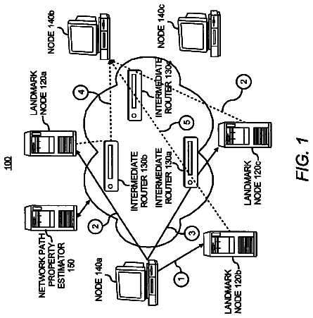
Machine learning approach for estimating a network path property
A network path property for nodes in a network is estimated using machine learning techniques.
US 8,660,035 B2 · Assignee: Apple, Inc. · Inventors: Zhang; Hang et al.
Sheet 1 of 17 from the published document. All sheets in the USPTO PDF
A method and system for using a communication network having a relay node to provide wireless communication with a mobile station. A ranging region is established with the mobile station in which the establishment of the ranging region includes the transmission of control information corresponding to the relay node. The mobile station is allowed to enter the communication network. The relay node is used to wirelessly communicate with the mobile station in at least one of the uplink and downlink directions.
1. Statement of the Technical Field The present invention relates to the field of wireless communications and more particularly to a method and system for providing a media access control ("MAC") layer control plane for wireless relay networks.
1 of 17 drawing sheets so far from the published document, cropped to the drawing. Every sheet is in the USPTO PDF.
What the patent claimed, word for word. All of it is now free to use.
1. Statement of the Technical Field
The present invention relates to the field of wireless communications and more particularly to a method and system for providing a media access control ("MAC") layer control plane for wireless relay networks.
As the demand for high speed broadband networking over wireless communication links increases, so too does the demand for different types of networks that can accommodate high speed wireless networking. For example, the deployment of IEEE 802.11 wireless networks in homes and business to create Internet access "hot spots" has become prevalent in today's society. However, these IEEE 802.11-based networks are limited in bandwidth as well as distance. For example, maximum typical throughput from a user device to a wireless access point is 54 MB/sec. at a range of only a hundred meters or so. In contrast, while wireless range can be extend through other technologies such as cellular technology, data throughput using current cellular technologies is limited to a few MB/sec. Put simply, as the distance from the base station increase, the need for higher transmission power increases and the maximum data rate typically decreases. As a result, there is a need to support high speed wireless connectivity beyond a short distance such as within a home or office.
As a result of the demand for longer range wireless networking, the IEEE 802.16 standard was developed. The IEEE 802.16 standard is often referred to as WiMAX or less commonly as WirelessMAN or the Air Interface Standard. This standard provides a specification for fixed broadband wireless metropolitan access networks ("MAN"s) that use a point-to-multipoint architecture. Such communications can be implemented, for example, using orthogonal frequency division multiplexing ("OFDM") communication. OFDM communication uses a spread spectrum technique distributes the data over a large number of carriers that are spaced apart at precise frequencies. This spacing provides the "orthogonality" that prevents the demodulators from seeing frequencies other than their own.
The 802.16 standard supports high bit rates in both uploading to and downloading from a base station up to a distance of 30 miles to handle such services as VoIP, IP connectivity and other voice and data formats. Expected data throughput for a typical WiMAX network is 45 MBits/sec. per channel. The 802.16e standard defines a media access control ("MAC") layer that supports multiple physical layer specifications customized for the frequency band of use and their associated regulations. However, the 802.16e standard does not provide support for multi-hop networks.
802.16 networks, such as 802.16j networks, can be deployed as multi-hop networks from the subscriber equipment to the carrier base station. In other words, in multi-hop networks, the subscriber device can communicate with the base station directly or through an intermediate device.
The complexity involved in supporting multi-hop networks in a robust manner necessarily involves sophisticated MAC control layer protocols. Such protocols do not exist. For example, as noted above, the IEEE 802.16e standard does not support multi-hop networks. The IEEE 802.16j standard for supporting multi-hop networks has been proposed, but the standard currently makes no provision for MAC layer control plane support.
It is therefore desirable to have method and system that provides MAC control plane functions to support wireless multi-hop relay networks, including but not limited to those operating in accordance with the IEEE 802.16 standards.
In accordance with one aspect, the present invention provides a method for using a communication network having a relay node to provide wireless communication with a mobile station. A ranging region is established with the mobile station in which the establishment of the ranging region includes the transmission of control information corresponding to the relay node. The mobile station is allowed to enter the communication network. The relay node is used to wirelessly communicate with the mobile station in at least one of the uplink and downlink directions.
In accordance with another aspect, the present invention provides a system for wirelessly communicating with a mobile station. A stationary relay node ranges with the mobile station, uses MAC control plane messages to establish wireless communications with the mobile station and wirelessly communicates with the mobile station in at least one of the uplink and downlink directions.
In accordance with another aspect, the present invention provides a method for wireless communication using a relay node in which a frame structure is implemented for communication with the relay node. The frame structure includes a downlink sub-frame and an uplink sub-frame. At least a portion of one of the downlink sub-frame and the uplink sub-frame is used to communication with the relay node.
Additional aspects of the invention will be set forth in part in the description which follows, and in part will be obvious from the description, or may be learned by practice of the invention. The aspects of the invention will be realized and attained by means of the elements and combinations particularly pointed out in the appended claims. It is to be understood that both the foregoing general description and the following detailed description are exemplary and explanatory only and are not restrictive of the invention, as claimed.
The accompanying drawings, which are incorporated in and constitute part of this specification, illustrate embodiments of the invention and together with the description, serve to explain the principles of the invention. The embodiments illustrated herein are presently preferred, it being understood, however, that the invention is not limited to the precise arrangements and instrumentalities shown, wherein:
FIG. 1 is a diagram of a system constructed in accordance with the principles of the present invention;
FIG. 2 is a block diagram of a first operational embodiment of the present invention;
FIG. 3 is a block diagram of a second operational embodiment of the present invention;
FIG. 4 is a block diagram of a third operational embodiment of the present invention;
FIG. 5 is a block diagram of a fourth operational embodiment of the present invention;
FIG. 6 is a block diagram of a fifth operational embodiment of the present invention;
FIG. 7 is a flow chart of an initial network entry process for a mobile station described from the point of view of the mobile station in the operational embodiments shown in FIGS. 2 and 4;
FIG. 8 is a flow chart of an initial network entry process for a mobile station described from the point of view of a relay node in the operational embodiments shown in FIGS. 2 and 4;
FIG. 9 is a flow chart of an initial network entry process for a mobile station described from the point of view of a base station in the operational embodiments shown in FIGS. 2 and 4; and
FIG. 10 is a diagram of an exemplary logical frame structure constructed in accordance with the principles of the present invention;
FIG. 11 is a diagram with examples of downlink traffic transmission arrangements;
FIG. 12 is a block diagram of a macro diversity intra-base station switching arrangement constructed in accordance with the principles of the present invention;
FIG. 13 is a flow chart of an intra-base station switching process from the perspective of a mobile station;
FIG. 14 is a flow chart of an intra-base station switching process from the perspective of a relay node;
FIG. 15 is a flow chart of an intra-base station switching process from the perspective of a base station;
FIG. 16 is a block diagram of a macro diversity inter-base station switching arrangement constructed in accordance with the principles of the present invention;
FIG. 17 is a flow chart of an inter-base station switching process from the perspective of a relay node; and
FIG. 18 is a flow chart of an inter-base station switching process from the perspective of a base station.
As an initial matter, reference may be made herein to "data plane" and "control plane." In general, the control plane includes configured or signaled information that determines the overall behavior, mappings, resource allocation and forwarding parameters that can be applied to all connection frames or frames of a service class. Such information is typically established and used to set up the network devices before any payload traffic is transmitted. Data plane refers to the frame processing functions that typically take place in real-time on a frame-by-frame basis.
In accordance with embodiments of the invention various MAC control plane embodiments for use in wireless networks using relays are described. While certain embodiments are discussed in the context of wireless networks operating in accordance with the IEEE 802.16 broadband wireless standard, which is hereby incorporated by reference, the invention is not limited in this regard and may be applicable to other broadband networks including those operating in accordance with other OFDM orthogonal frequency division ("OFDM")-based systems including the 3rd Generation Partnership Project ("3GPP") and 3GPP2 evolutions. Similarly, the present invention is not limited solely to OFDM-based systems and can be implemented in accordance with other system technologies, e.g., CDMA.
Referring now to the drawing figures in which like reference designators refer to like elements, there is shown in FIG. 1, a system constructed in accordance with the principles of the present invention and designated generally as "10." System 10 includes base stations 12, relay nodes 14 and mobile stations 16. Base stations 12 communicate with one another and with external networks, such as the Internet (not shown), via carrier network 18. Base stations 12 engage in wireless communication with relay nodes 14 and/or mobile stations 16. Similarly, mobile stations 16 engage in wireless communication with relay nodes 14 and/or base stations 12.
Base station 12 can be any base station arranged to wirelessly communicate with relay nodes 14 and/or mobile stations 16. Base stations 12 include the hardware and software used to implement the functions described herein to support the MAC control plane functions. Base stations 12 include a central processing unit, transmitter, receiver, I/O devices and storage such as volatile and nonvolatile memory as may be needed to implement the functions described herein.
Mobile stations 16 can be any mobile station including but not limited to a computing device equipped for wireless communication, cell phone, wireless personal digital assistant ("PDA") and the like. Mobile stations 16 also include the hardware and software suitable to support the MAC control plane functions needed to engage in wireless communication with base station 12 either directly or via a relay node 14. Such hardware can include a receiver, transmitter, central processing unit, storage in the form of volatile and nonvolatile memory, input/output devices, etc.
Relay node 14 is used to facilitate wireless communication between mobile station and base station 12 in the uplink (mobile station 16 to base station 12) and/or the downlink (base station 12 to mobile station 16). A relay node 14 configured in accordance with the principles of the present invention includes a central processing unit, storage in the form of volatile and/or nonvolatile memory, transmitter, receiver, input/output devices and the like. Relay node 14 also includes software to implement the MAC control plane functions described herein. Of note, the arrangement shown in FIG. 1 is general in nature and specific communication embodiments constructed in accordance with the principles of the present invention are described with reference to FIGS. 2-6 below. Of note, according to an embodiment, base stations 12 and relay nodes 14 implemented in accordance with the principles of the present invention are fixed, i.e. non-moving devices, but the invention is not limited to such. It is contemplated that these devices may move. Mobile stations 16 can be fixed, stationary or moving.
FIGS. 2-6 are diagrams showing five different exemplary operational embodiments for base stations 12, relay nodes 14 and mobile stations 16 in accordance with the principles of the present invention. It is noted that carrier network 18 is not shown in FIGS. 2-6 to simplify explanation of the operating embodiments.
FIG. 2 is a diagram showing unbalanced relay operation. As is shown in FIG. 2, mobile station 16 communicates with base station 12 via relay node 14 in the uplink direction only. Base station 12 communicates in the downlink direction directly with mobile station 16. Base station 12 is also shown as engaging in bi-directional communication with relay node 14 so that base station 12 can receive data from mobile station 16 via relay node 14 and engage in MAC control plane communications with relay node 14. The unbalanced relay arrangement shown in FIG. 2 relieves mobile station 16 from concerns over the peak to average power ratio ("PAPR") and reduces the imbalance in the downlink ("DL")/uplink ("UL") link budget. Such occurs, for example, because the base station 12 is capable of much higher power transmission and is much more sensitive on the receiving side than mobile station 16 for wireless communications such as orthogonal frequency division multiplexed ("OFDM") communications. In other words, within a given area supported by base station 12, using an unbalanced communication arrangement such as that shown in FIG. 2 allows a more even transmission power arrangement on the uplink and downlink because mobile station 16 can communicate with relay node 14 in the UL direction, which is presumably closer to mobile station 16 than base station 12 (at least for purposes of the present embodiment). In addition, the present arrangement as is shown in FIG. 2 does not require any implementation or programmatic software changes or enhancements to mobile station 16 or base station 12 with respect to downlink communication because such is accomplished directly between base station 12 and mobile stations 16 as is known in the art.
In the uplink direction, base station 12 schedules uplink transmission for mobile station 16 and relay node 14. Mobile station 16 makes its uplink transmission which is received and decoded by relay node 14. Relay node 14 relays the traffic to base station 12. Instead of ranging to base station 12, mobile station 16 ranges to relay node 14. As used herein, the term "ranging" is used as understood by one of ordinary skill in the art. "Ranging" refers to the process used in OFDM wireless communications to adjust the arrival time for different mobile stations 16 communicating with a single base station 12. The ranging process is also used to establish the transmit power for mobile station 16. The ranging process is analogous to a "handshake" between mobile station 16 and its communication partner, i.e. relay node 14, in the uplink direction. The inclusion of relay node 14 in the embodiment shown in FIG. 2 is transparent to mobile station 16. In other words, because DL communication comes from base station 12 and not relay node 14, mobile station does not know that its UL communication is not directly with base station 12 and is instead with relay node 14. This arrangement provides a suitable low-cost, fixed relay node implementation embodiment. With respect to MAC enhancement, no additional MAC capability, e.g., downlink re-fragmentation, scheduling, etc., is needed in this embodiment.
However, management messages relating to relay node 14 are used to support the functionality described in this embodiment and might include, for example, a relay node report message that allows a relay node to report ranging codes, channel quality index, channel and downlink hybrid automated repeat request ("HARQ") error control method acknowledgement channels and combined uplink traffic HARQ status messages for multiple mobile stations 16. Another MAC management message may include a message sent by base station 12 to relay node ("RN") 14 which enables base station 12 to indicate the uplink connection identification numbers supporting communication sessions.
A second operational embodiment of the present invention is described with reference to FIG. 3. FIG. 3 shows a coverage hole 20 formed by non-overlapping coverage regions 22 supported by corresponding base stations 12. In other words, each base station 12 supports a coverage region 22 for communication with devices in the corresponding coverage region 22. However, there are situations in which coverage areas 22 may not overlap, thereby forming a "coverage hole" 20. FIG. 3 shows mobile station 16 positioned within coverage hole 20. In such case, absent a solution, mobile station 16 would lose wireless communication with base stations 12. In other words, a mobile station 16 at the edge of a coverage region 22, i.e., cell is unable to decode broadcast control messages transmitted by any of base stations 12. In this case, relay node 14 and its corresponding relay node coverage area 24 provides coverage within coverage hole 20, thereby effectively eliminating the coverage hole and allowing a mobile station 16 in coverage hole 20 to wirelessly communicate with one or more base stations 12. Note, although FIG. 3 shows circular coverage in some areas 22, the present invention is not limited to such. Coverage zones 22 shown in various shapes in the drawing figures purely for ease of explanation and understanding, it being recognized that coverage areas 22 can take the form of different shapes depending on the configuration of the antennas within each base station 12.
In the case of the operational embodiment shown in FIG. 3, relay node 14 operates much like a base station 12 in that it relays all DL broadcast messages to mobile station 16 and relays all DL and UL unicast messages and traffic between mobile station 16 and base station 12. Relay node 14 also manages the ranging operation with respect to its supported mobile stations 16, conducts data scheduling and creates local map messages. Of note, the operation of mobile station 16 is not transparent because base station 12 is transmitting in the downlink to a relay node 14. As such, transmissions to relay node 14 at the MAC layer may be re-fragmented for transmission to base station 12. The data plane aspects of the MAC enhancement are referred to herein as "R-MAC". As is discussed below in detail, a set of messages for communication between relay node 14 and base station 12 to support MAC control plane functions are implemented in accordance with the present invention.
A third operational embodiment is described with reference to FIG. 4. The embodiment shown in FIG. 4 is used to enhance throughput within a coverage region 22, i.e., cell. In this case, mobile station 16 at the edge of coverage region 22 is able decode broadcast control messages from base station 12. However, because mobile station 16 is at the edge of the coverage region 22, its capacity for communication with base station 12 is severely attenuated due to the low signal strength resulting from the distance from base station 12.
In this embodiment, as noted above, mobile station 16 receives broadcast control messages from base station 12. Relay node 14 relays only DL and UL unicast messages and traffic to/from mobile station 14. In this case, relay node 14 performs data scheduling and downlink re-fragmentation. Accordingly, as with the previous embodiment (FIG. 3), MAC control plane protocol is enhanced to provide a relay node MAC control plane enhancement ("R-MAC") to support this refragmentation.
With respect to the operation of mobile station 16, operation by mobile station 16 is not transparent because mobile station 16 may support the R-MAC control plane functions. In addition, a type interference control of relay node 14 is used so that communications to/from mobile station 16 can properly be supported.
The fourth operational embodiment is described with reference to FIG. 5. In the embodiment shown in FIG. 5, coverage is extended to mobile station 16 beyond the coverage area 22 of base station 12. Relay nodes 14 are arranged to have overlapping relay coverage nodes area 24. In this arrangement, relay nodes 14 include the full set of operational functions provided by a base station 12 plus the R-MAC layer. In addition, connection identification information for particular communication sessions as well as the implementation of the privacy functions are provided on an end-to-end basis, i.e. from mobile stations 16 to base station 12. Relay node 14 also supports local DL channel description ("DCD"), UL channel description ("UCD"), mobile neighboring advertisement ("MOB_NBR_AVD") messages, and the like. DCD messages provide downlink channel configuration information, such as power and timing adjustment rules. UCD messages include, for example, ranging code division information. MOB_NBR_AVD messages provide information relating to neighboring cells, HO information, etc. Relay node 14 also supports the information needed to route the mobile 16 station connection through the series of relay nodes 14 for communication with base station 12.
As with the previous two embodiments, the operation of mobile station 16 includes the new R-MAC layer. This embodiment also implements an independent data transmit and receive schedule. Further, in accordance with the present embodiment, interference control of relay nodes 14 is not significant because the mobile station 16 only communicates with a relay node 14 (as to compared to both a relay node 14 and base station 12 in some capacity or form).
A fifth exemplary operational scenario is described with reference to FIG. 6. The embodiment shown in FIG. 6 can be used to boost system capacity for a wireless communication transmission technology different than that supported by base station 12. For example, the embodiment shown in FIG. 6 shows code division multiple access ("CDMA") wireless communication between relay node 14 and mobile station 16 but uses multiple input, multiple output ("MIMO") OFDM wireless communication between base station 12 and relay node 14. Multiple Input, Multiple Output Orthogonal Frequency Division Multiplexing ("MIMO-OFDM") is an OFDM technology that uses multiple antennas to transmit and receive radio signals. MIMO-OFDM allows service providers to deploy wireless broadband systems that take advantage of the multi-path properties of environments using base station antennas that do not necessarily have line of sight communications with the mobile station.
MIMO systems use multiple antennas to simultaneously transmit data to the receiver, which processes the separate data transmissions. This process, called spatial multiplexing, can be used to proportionally boost the data-transmission speed by a factor equal to the number of transmitting antennas. In addition, since all data is transmitted both in the same frequency band and with separate spatial signatures, this technique utilizes spectrum very efficiently. The result is that CDMA system capacity is enhanced without actually impacting or requiring the upgrade of CDMA base stations and/or requiring the deployment of OFDM-based mobile stations 16.
Under the architecture shown in the embodiment of FIG. 6, cell-wise backhaul is provided. Using a technology such as MIMO-OFDM for communication between base station 12 and relay node 14 allows the benefit of MIMO-OFDM transmission to be maximized. It is contemplated that such an arrangement can be provided by implementing MIMO-OFDM and CDMA at the physical layer within relay node 14. As such, mobile station 16 and its use of CDMA is transparent to mobile station 16. In other words, the embodiment shown in FIG. 6 allows relay node 14 to act as a base station for the CDMA system. Although the embodiment shown in FIG. 6 shows CDMA and MIMO-OFDM technologies, the general proposition of the embodiment in FIG. 6 is that relay node 14 can provide an air interface translation function. In other words, the present invention is not limited solely to CDMA to MIMO-OFDM translation.
Of note, the operational embodiments shown in FIGS. 2-6 as well as other drawing figures herein showing relay node 14 are not limited solely to the use of a particular piece of hardware. It is contemplated that mobile stations themselves can serve as relay nodes within the context of the present invention provided that mobile stations 16 are equipped with the software to implement the relay node functions described herein. In other words, a mobile station can serve as a relay node 14 provided that it is equipped with software supporting relay node functions.
In accordance with the present invention, a number of functions are defined to support the aforementioned operational embodiments. These MAC layer control functions provide the ability for mobile station 16 to enter and operate within a relay-based network. These functions include ranging, initial network entry for mobile station 16 and defining a frame structure for wireless communication between and among mobile station 16, base station 12, and relay node 14. These functions also include the establishment of broadcast/unicast data/message transmission, and scheduling signaling. In addition, MAC layer control functions are provided for fast access point ("AP") switching, relay node-related MAC management messages and sleep/idle mode operation. Each of these functions are described herein.
Ranging
As an initial matter, it is noted that the implementation of the ranging function for the embodiments shown in FIGS. 2, 3, 5, and 6 are the same as is currently known in the art, e.g., the same as in the IEEE 802.16d and e standards. However, current standards do not provide or propose support for the operational embodiment shown FIG. 4 (system capacity enhancement through the use of relay nodes 14). A ranging design for that operational embodiment is described herein. In accordance with the present invention, there are two options for supporting ranging for the capacity enhancement embodiment (FIG. 4). As a first option, three types of ranging regions can be defined, resulting in shorter delay to establish ranging, but high complexity with respect to the relay node 14 ranging process. As a second option, two types of ranging regions can be defined, resulting in a long ranging establishment delay but low complexity with respect to the relay node 14 ranging process.
Regarding the first option, the three ranging regions include a common initial ranging region for the first step initial ranging of network entry or re-entry, a common AP switch ranging region and a private ranging region. For the common initial ranging region, all of the access points in the cell, i.e., the base station 12 and all relay nodes 14, monitor this region. The region may appear every N frames and is described in base station 12's UL-MAP. With respect to code set division, the code set is divided to enable mobile stations 16 to indicate the preferred access point. The code set for the common initial ranging region is divided among all access points in a cell. Mobile station 16 sends a code selected within the domain of the relay node 14 if the mobile station 16 selects a particular relay node 14 as its access point. The second type of ranging region within this first option is the establishment of a common access point switch ranging region. All of the access points in a cell monitor this region, and the region may appear ever N frames and is described in base station 12's UL-MAP. The code set is divided to enable base station 12 to ultimately indicate the access point, and each access point is allocated a code domain. To enable mobile 16 to use the dedicated code for the first step of AP switch ranging, the base station 12 or parent relay node 14 reserves a set of codes as temporary access point switch codes for intra-base station 12 access point switching. This arrangement speeds up the AP switching procedure. Mobile station 14 uses the temporary access point switch code on the common AP switch ranging region. Mobile station 14 uses the code selected within the domain of a selected relay node 14 between the common AP switch ranging region.
Finally, the private ranging region of the first option is described. In this region, each relay node and base station has its own private ranging region used for the second step of the initial ranging process and the second step of the AP switch ranging process. The second step means that after the first step of ranging process described above, the power and timing are aligned with the requirements of the access point. Private ranging region also allows for bandwidth request ranging and periodical ranging as well. The private ranging region is only monitored by relay nodes 14. With respect to code set division, relay node 14 reserves a code set for the second step ranging whether for AP switching or initial ranging. The remaining codes are divided as bandwidth request codes and periodic ranging codes. The length of the code may be shorter than those used for base stations 12, e.g., 74 versus 144 bits, since the interference within the region of a relay node 14 is less than compared with the base station because a smaller group of mobile stations 16 are supported by a relay node 14.
With respect to the second option, the common initial ranging and common AP switch regions are combined as a single region. Under this option, the access point will not be able to determine the purpose of the ranging, i.e. inter-base station access point switching or initial ranging based on the code. Accordingly, a MAC header is defined so that the access point can poll mobile station 16 to determine the purpose of the ranging. Under the second option, a private ranging region is also established and is the same as that described above with respect to the first option.
With respect to both option 1 and option 2, it is contemplated that the available codes, e.g., 250 different codes, are arranged in a block in which different groups of codes are assigned to the different domains. For example, with respect to the common initial ranging region described with respect to option 1, it is contemplated that the block of 250 codes can be divided so that there is a domain for base station 12, and a separate domain for each relay node 14 within the cell. With respect to the common switch ranging region for options 1 and 2, the block can be divided and a domain group reserved for intra-base station 12 switching and a separate group of codes assigned to establish domains for the various relay nodes within the group of common access points for inter-base station switching. Similarly, with respect to the private ranging region, the block of available codes can be divided into a second step ranging group domain, a periodic request domain, and a bandwidth request domain. Of note, with respect to the private ranging region, a shorter code length means a shorter ranging opportunity which means a smaller defined ranging region. Of note, for ranging purposes, the MAC header described above for option 2 can be added as an additional type in the feedback MAC header. The general concept of a feedback MAC header is known. However, the implementation of a ranging purpose function within that header is provided in accordance with the present invention.
Mobile Station Initial Network Entry
The present invention defines functions and procedures for allowing network entry of a mobile station 16 to a network having relay nodes 14. Initial network entry relates to the selection of codes, such as OFDMA codes, from the UL-MAP and DL-MAP by mobile station 16. Mobile station 16 selects a code base and tells base station 12 (or relay node 14) that mobile station 16 is going to join the network. In this case, base station 12 and/or relay node 14 monitor the ranging region, described above, to facilitate initial network entry of mobile station 16.
An exemplary arrangement for the operational embodiments shown in FIGS. 2 and 4 are described first. As an initial matter, it is presumed that all mobile stations 16 in this exemplary arrangement are able to decode broadcast control messages transmitted by base station 12. In these embodiments, mobile station 16 enters the network through base station 12. A common initial ranging region is dedicated for initial ranging, i.e., the common ranging region is used for the first step of initial ranging. The common ranging region is described in an uplink channel description ("UCD") and/or UL-MAP message. Base station 12 and all relay nodes 14 within the coverage region 22 monitor this ranging region constantly in order to speed up initial network entry. As discussed above, the available codes are divided among base station 12 and relay nodes 14 within the same coverage region 22, i.e., within the same cell. Base station 12 or relay node 14 is associated with the code set used by mobile station 16 to indicate its preferred access point in the first step of initial ranging. For example, these codes can be generated using the cell's uplink ID which can be a 7-bit field.
The method for selecting base station 12 is the same as is presently known in the art with respect to the initial network entry of a mobile station 16. Downlink channel description ("DCD") and UCD synchronization is performed by having mobile station 16 monitor DCD messages transmitted by base station 12. However, base station 12 adds information related to relay node 14 such as a preamble index, transmit region, etc., to the DCD message. Similarly, mobile station 16 monitors the UCD messages transmitted by base station 12. In this case, base station 12 adds relay information such as the code set corresponding to the relay node 14 for the first step of initial ranging, the ranging region, the number of hops (relay node 14 hops) to base station 12 as well an uplink relay identification number. Of note, the uplink ID for relay node 14 and the cell ID for the uplink are typically planned in advance and pre-assigned.
The operational embodiments shown in FIGS. 2 and 4 also involve the selection of an access point, e.g., base station 12 or relay node 14. In accordance with the present invention, mobile station 16 is arranged to detect relay preambles based on the general quantity measurement and number of hops. In accordance with the measurement and number of hops, the top 3 candidate access points are selected.
Mobile station 16 monitors the DL-MAP and UL-MAP to understand the common initial ranging region. Mobile station 16 selects a ranging code from the code set associated with the selected access point as was sent in the common initial ranging region. All relay nodes 14 and the base station 12 within coverage region 22 monitor the common initial ranging region and any relay node 14 which detected the code transmission informs base station 12 in the form of the received code index and signal strength. Base station 12 assigns a dedicated code for the second set of initial ranging as well time/power adjustment data. Base station 12 determines the access point for mobile station 16 based on
the code index received from mobile station 16, i.e., the intended access point from the perspective of mobile station 16, and
the load on the relay node 14 selected by mobile station 16.
The second step of initial ranging is done in connection with the selected relay node 14. In this case, base station 12 sends a ranging response message ("RNG-RSP") which
accepts the access point selected by mobile station 16 or suggests another access point,
assigns the CID, and
includes any timing/power adjustments that may be used by mobile station 16 to facilitate the ranging process. Mobile station 16 then starts to monitor the transmit region corresponding to the selected relay node 14.
The actual second step of initial ranging using the selected access point is the same as is known in the present art with the exception that the mobile station 16 has a dedicated code assigned for the second step of ranging after obtaining the relay transmit region. Of note, the above description of initial network entry for mobile station 16 with respect to the operational embodiment shown in FIGS. 2 and 4 includes a generalized discussion of the process flow and dynamics among mobile station 16, relay node 14 and base station 12. The process flow for initial network entry for mobile station 16 is described from the point of view of mobile station 16 in FIG. 7, from the point of view of relay node 14 in FIG. 8 and from the point of view of base station 12 in FIG. 9 for the operational embodiments shown in FIGS. 2 and 4.
Referring to FIG. 7, with respect to mobile station 16, mobile station 16 selects the cell, i.e. coverage region 22 it wishes to communicate within (Step S100). Mobile station 16 synchronizes the DCD message as described above (Step S102). The preferred access point is selected by mobile station 16 (Step S104) and transmitted to base station 12 and sends this as part of the first step initial ranging code (Step S106). Mobile station 16 then waits for the RNG-RSP from base station 12 (Step S108).
When mobile station 16 receives the RNG-RSP from base station 12 (Step S110), mobile station 16 engages in second step initial ranging with the selected access point using a dedicated code (Step 112). Recall that the RNG-RSP received from base station 12 includes the access point selected by base station 12.
If, during Step S108, the RNG-RSP is not received and a predetermined timer ("T1") expires (Step S114), the first step initial ranging code is re-sent a predetermined number of times until its retry quantity is exhausted (Step S116). Once the retry quantity is exhausted, mobile station 16 begins the network re-entry process again (Step S118).
Turning now to FIG. 8, relay node 14 monitors the common initial ranging region (Step S120) until a code transmission is detected (Step S122). When a code transmission is detected, relay node 14 evaluates the code to determine whether mobile station 16 selected a code corresponding to that relay node 14 (Step S124). If the code transmission does not indicate that the particular relay node 14 has been selected, the assigned code is released by relay node 14 (S-126). If relay node 14 was selected, a "code_grab" message is sent to base station 12 (Step S128) indicating that the mobile station 16 selected the particular relay node 14. Relay node 14 decodes the RNG-RSP message sent from base station 12 to mobile station 16 (in other words, it detects the RNG-RSP message as well) or receives a separate MAC layer message from base station 12. Relay node 14 evaluates the message to determine whether a CID has been assigned to mobile station 16 (Step S132). If a CID has not been assigned, relay node 14 releases the assigned code. If a CID has been assigned, relay node 14 monitors the assigned code transmission on its own private ranging region for the subsequent ranging process, i.e. the second step initial ranging (Step S134).
The description continues in the full USPTO document.
About 6,402 words. The USPTO PDF has it with every drawing.
Fees are due 3.5, 7.5 and 11.5 years after grant. This patent expired on February 25, 2026, so the fee marked "not paid" was the one that went unpaid.
Wireless Relay Network Media Access Control Layer Control Plane System and Method
Filed Nov 2006 · published Nov 2008Wireless relay network media access control layer control plane system and method
Filed Nov 2006 · granted Feb 2014Earlier publications, parents and continuations. None of them can still be enforced, or this patent would not be listed.
Prior art cited by the examiner or applicant. Useful when you check your own idea for novelty.
Everything on this page comes from the documents linked above.