Cross-reference to related applications
Not Applicable.
Background
Background and Relevant Art
Computer systems and related technology affect many aspects of society. Indeed, the computer system's ability to process information has transformed the way we live and work. Computer systems now commonly perform a host of tasks (e.g., word processing, scheduling, accounting, etc.) that prior to the advent of the computer system were performed manually. More recently, computer systems have been coupled to one another and to other electronic devices to form both wired and wireless computer networks over which the computer systems and other electronic devices can transfer electronic data. Accordingly, the performance of many computing tasks are distributed across a number of different computer systems and/or a number of different computing environments.
Many businesses use enterprise resource planning ("ERP") to coordinate all resources, information, and activities needed to complete business processes such as order fulfillment and billing. An ERP system typically supports most of the business system and maintains tables and other entities in a common database. For example, all the data for manufacturing, supply chain management, financials, projects, human resources, etc., can be maintained in a common database. Through the common database different business units can store and retrieve information in real-time. ERP systems are advantageous for a number of reasons, including standardization, lower maintenance, providing a common interface for accessing data, and greater and more efficient reporting capabilities.
For example, businesses are typically required to report data for inclusion in Standard Industrial Classification ("SIC") or North American Industry Classification System ("NAICS"). Many businesses also report data to regulatory bodies, such as, for example, the Environmental Protection Agency ("EPA"), Securities and Exchange Commison ("SEC"), and Public Company Accounting Oversight Board ("PCAOB"). For example, publicly held corporations can report financial data including off-balance sheet transactions, pro-forma figures, stock transactions for corporate officers, and auditing information to the SEC for compliance with federal law.
As such, ERP data is typically formulated for generic use in reporting and compliance. For example, ERP data can be formatted for generating statistics for broad economic analysis (e.g., NAICS reporting), for statutory compliance (e.g., Sarbanes-Oxley), etc., in accordance with generic externally defined formats. Thus, ERP data typically lacks any industry-specific structure.
This is problematic since the ability of an organization to understand the underlying basis for generated ERP data in these and other reports is important to staying competitive in a given field. For example, such understanding can be useful when evaluating potential vertical industry strategies, such as, for example, introducing a new product, changing customer service procedures, that might impact performance. Further, in many organizations, there is no defined link between ERP data and business components that drive potential vertical industry strategies. Thus, the usefulness of ERP data in making decisions with respect to vertical-industry strategies is limited. For example, it is difficult for an organization to tell from ERP data what business components correspond more or less strongly to the ERP data.
Brief summary
The present invention extends to methods, systems, and computer program products for linking enterprise resource planning data to business capabilities. A computer architecture accesses a schema-based model for the organization. The schema-based model models a plurality of interrelated business capabilities for the organization at a specified level of detail. Each business capability represents a portion of what work the organization does.
The computer architecture accesses a schema-based representation of a portion of enterprise resource planning data for the organization. The portion of enterprise resource planning data is formatted for purposes of report generation. The computer architecture identifies an express schema-based link between the portion of enterprise resource planning data and each of the plurality of interrelated business capabilities. Each schema based-link links the portion of enterprise resource data to a corresponding business capability
Each schema-based link includes property values indicative of a corresponding business capability's contribution to the portion of enterprise resource planning data. The computer architecture utilizes the property values to identify what business capabilities specifically contribute to the portion of enterprise resource data. A business related decision is made with respect to the specified portion of enterprise resource planning data based on the identified business capabilities and the property values.
This summary is provided to introduce a selection of concepts in a simplified form that are further described below in the Detailed Description. This Summary is not intended to identify key features or essential features of the claimed subject matter, nor is it intended to be used as an aid in determining the scope of the claimed subject matter.
Additional features and advantages of the invention will be set forth in the description which follows, and in part will be obvious from the description, or may be learned by the practice of the invention. The features and advantages of the invention may be realized and obtained by means of the instruments and combinations particularly pointed out in the appended claims. These and other features of the present invention will become more fully apparent from the following description and appended claims, or may be learned by the practice of the invention as set forth hereinafter.
Brief description of the drawings
In order to describe the manner in which the above-recited and other advantages and features of the invention can be obtained, a more particular description of the invention briefly described above will be rendered by reference to specific embodiments thereof which are illustrated in the appended drawings. Understanding that these drawings depict only typical embodiments of the invention and are not therefore to be considered to be limiting of its scope, the invention will be described and explained with additional specificity and detail through the use of the accompanying drawings in which:
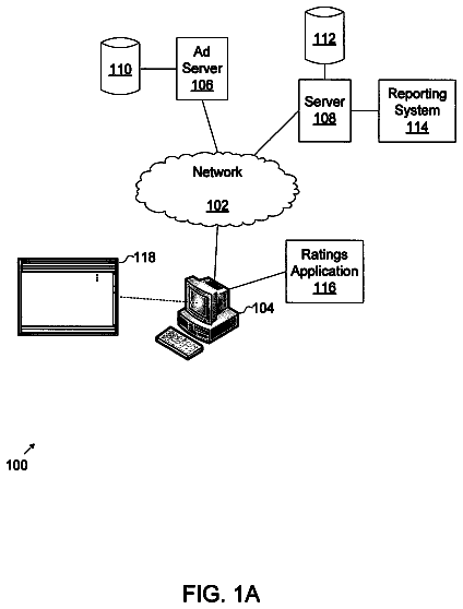
FIG. 1A illustrates an example computer architecture for generating enterprise resource planning data.
FIG. 1B illustrates an example computer architecture that facilitates linking enterprise resource planning data to business capabilities.
FIG. 2 illustrates a portion of an example capability modeling schema that can be used for efficiently and flexibly business modeling based upon structured business capabilities.
FIGS. 3A and 3B illustrate a visual representation of a collection of business capabilities at varied levels of detail.
FIG. 3C illustrates an example of a modeled business capability.
FIG. 3D illustrates a first view of an example of a network of modeled business capabilities.
FIG. 3E illustrates a second view of the example of a network of modeled business capabilities.
FIG. 4 illustrates a capability schema and capability SLE schema relative to an enterprise resource planning data schema.
FIG. 5 illustrates an example computer architecture that facilitates determining what business capabilities contribute to enterprise resource planning data.
FIG. 6 illustrates an example flowchart of a method for making a business related decision based on how a specified portion of enterprise resource planning data maps to an organization's business capabilities.
Detailed description
The present invention extends to methods, systems, and computer program products for linking enterprise resource planning data to business capabilities. A computer architecture accesses a schema-based model for the organization. The schema-based model models a plurality of interrelated business capabilities for the organization at a specified level of detail. Each business capability represents a portion of what work the organization does.
The computer architecture accesses a schema-based representation of a portion of enterprise resource planning data for the organization. The portion of enterprise resource planning data is formatted in a format for purposes of report generation. The computer architecture identifies an express schema-based link between the portion of enterprise resource planning data and each of the plurality of interrelated business capabilities. Each schema based-link links the portion of enterprise resource data to a corresponding business capability
Each schema-based link includes property values indicative of a corresponding business capability's contribution to the portion of enterprise resource planning data. The computer architecture utilizes the property values to identify what business capabilities specifically contribute to the portion of enterprise resource data. A business related decision is made with respect to the specified portion of enterprise resource planning data based on the identified business capabilities and the property values.
Embodiments of the present invention may comprise or utilize a special purpose or general-purpose computer including computer hardware, as discussed in greater detail below. Embodiments within the scope of the present invention also include physical and other computer-readable media for carrying or storing computer-executable instructions and/or data structures. Such computer-readable media can be any available media that can be accessed by a general purpose or special purpose computer system. Computer-readable media that store computer-executable instructions are physical storage media. Computer-readable media that carry computer-executable instructions are transmission media. Thus, by way of example, and not limitation, embodiments of the invention can comprise at least two distinctly different kinds of computer-readable media: physical storage media and transmission media.
Physical storage media includes RAM, ROM, EEPROM, CD-ROM or other optical disk storage, magnetic disk storage or other magnetic storage devices, or any other medium which can be used to store desired program code means in the form of computer-executable instructions or data structures and which can be accessed by a general purpose or special purpose computer.
A "network" is defined as one or more data links that enable the transport of electronic data between computer systems and/or modules and/or other electronic devices. When information is transferred or provided over a network or another communications connection (either hardwired, wireless, or a combination of hardwired or wireless) to a computer, the computer properly views the connection as a transmission medium. Transmissions media can include a network and/or data links which can be used to carry or desired program code means in the form of computer-executable instructions or data structures and which can be accessed by a general purpose or special purpose computer. Combinations of the above should also be included within the scope of computer-readable media.
Further, upon reaching various computer system components, program code means in the form of computer-executable instructions or data structures can be transferred automatically from transmission media to physical storage media (or vice versa). For example, computer-executable instructions or data structures received over a network or data link can be buffered in RAM within a network interface module (e.g., a "NIC"), and then eventually transferred to computer system RAM and/or to less volatile physical storage media at a computer system. Thus, it should be understood that physical storage media can be included in computer system components that also (or even primarily) utilize transmission media.
Computer-executable instructions comprise, for example, instructions and data which cause a general purpose computer, special purpose computer, or special purpose processing device to perform a certain function or group of functions. The computer executable instructions may be, for example, binaries, intermediate format instructions such as assembly language, or even source code. Although the subject matter has been described in language specific to structural features and/or methodological acts, it is to be understood that the subject matter defined in the appended claims is not necessarily limited to the described features or acts described above. Rather, the described features and acts are disclosed as example forms of implementing the claims.
Those skilled in the art will appreciate that the invention may be practiced in network computing environments with many types of computer system configurations, including, personal computers, desktop computers, laptop computers, message processors, hand-held devices, multi-processor systems, microprocessor-based or programmable consumer electronics, network PCs, minicomputers, mainframe computers, mobile telephones, PDAs, pagers, routers, switches, and the like. The invention may also be practiced in distributed system environments where local and remote computer systems, which are linked (either by hardwired data links, wireless data links, or by a combination of hardwired and wireless data links) through a network, both perform tasks. In a distributed system environment, program modules may be located in both local and remote memory storage devices.
Generally, a business capability indicates "what" work is performed, such as, for example, "Purchase Goods". Entities that contribute to the performance of a capability indicate "how" work is performed, such as, for example, an employee uses an software application to generate a request for proposal ("RFP") and sends the RFP to prospective sellers, a Web service receives bids from prospective sellers, employees and automated analysis tools interact to evaluate received bids and identify a small subset of the best bids, a management committee then conducts a review process over small subset, a final selected bid is approved by the CEO, the final selected bid is then forwarded to purchasing, purchasing uses a Web service to purchase goods from the winning organization.
Multiple different implementations of "how" work is performed can each contribute to "what" work is performed. For example, for an airline, a first combination of entities from various business layers can be blended together to represent online check in, a second different combination of entities from various business layers can be blended kiosk check in, and a third different combination of entities from various business layers can be blended counter check in, for airline flights. Each of online check in, kiosk check in, and counter check in can contribute to a business capability for checking in passengers.
FIG. 1A illustrates example computer architecture 100 that facilitates generating enterprise resource planning ("ERP") data for organization 190. Organization 190 can be virtually any type of business related entity, such as, for example, a corporation (profit or non-profit), a partnership, a limited partnership ("LP"), a limited liability partnership ("LLP"), a limited liability corporation ("LLC"), a sole proprietorship, etc. A business architecture can include both internal (controlled by organization 190) and external (not controlled by organization 190) business capabilities.
Referring to FIG. 1A, computer architecture 100 includes ERP system 151. Generally, ERP system 151 can integrate a variety of business related functions for organization 190. For example, ERP system 151 can permit software modules 161, including manufacturing 152, financials 153, projects 154, human resources 156, etc., to access data through the use of common database 162. Each of software modules 161 can have access to common database 162 to store and retrieve data, facilitating integrated operation between software modules 161.
Data aggregation and reporting module 157 can access data from database 162 and generating reporting and other types of data. For example, data aggregation and reporting module 157 can generate enterprises resource planning data 101. Enterprises resource planning data 101 can include a variety of different types of data, such as, for example, master data (related to customers, vendors, etc.), transaction data (related to orders, receipts, etc), and lookup values. ERP data can for formatted for a variety of different purposes.
For example, NAICS reporting data 102 can be formatted for submission to the United States census bureau and/or for submission to other private entities that track industry-wide dat. SEC reporting data 103 can be formatted for submission to Public Company Accounting Oversight Board ("PCAOB") for compliance with the Sarbanes-Oxley act. Other financial data 104 (e.g., spending data by business unit) and other data 105 can be formatted for specific use by organization 190. As such, organization 109 can use enterprises resource planning data 101 (along with other data), when making business related decisions.
FIG. 1B illustrates example computer architecture 100 that facilitates linking enterprise resource planning data 101 to business capabilities 111. Business capabilities 111 include a plurality of business capabilities included business capabilities 112, 113, and 114. Each of business capabilities 112, 113, and 114 can each be part of a model that models the business architecture for organization 190. A business capability's contribution to a portion of ERP data is modeled in a schema-defined link from the business capability to organizational strategy. That is, a link can link ERP data to capabilities of an organization that transform the data during end-to-end business processes. For example, links 107 link the contributions of business capabilities 101 to enterprise resource planning data 101.
A business capability can have a link to each portion of enterprise resource data to which it contributes. Through links, each business capability can contribute to zero or more different portions of enterprise resource planning data. For example, business capability 112 can contribute to NAICS reporting data 102 and other data 105. Thus, links 107 can include links from business capability 112 to each of NAICS reporting data 102 and other data 105. Business capability 113 can contribute to NAICS reporting data 102, SEC reporting data 103, and other financial data 104. Thus, links 107 can include links from business capability 113 to each of NAICS reporting data 102, SEC reporting data 103, and other financial data 104. Business capability 114 may contribute to other types and/or formats of ERP data (not shown) in enterprise resource planning data 101. Thus, links 107 can include links from business capability 114 to each of other types and/or formats of ERP data.
Values on links 107 indicate a level of contribution from a business capability to a portion of ERP data. Virtually any mechanism for determining one contribution relative to another can be used. In some embodiments, numerical values are used. In these embodiments, higher numerical values correlate to higher contributions and lower number values correlate to lower contributions.
In some embodiments, business models and data format definitions for business capabilities are generally described as indicated in Table 1.
TABLE-US-00001 TABLE 1 Models Models serve to group capabilities into distinct groups that describe a single business. Models can contain all the capabilities defined for the business as well as how any defined capabilities relate to each other in terms of hierarchical decomposition and process flow relationships. Models facilitate the segmentation of data in a repository into distinct business models which can be compared with one another but are separate from each other. Further, while capability data is defined within a model, other data elements of the data model are outside of the model and facilitate the comparison of different models with one another. Capabilities Capabilities are individual business functional areas that are modeled in at least three different ways in the model. Capabilities can be modeled as individual things with their own set of properties; as a decomposition hierarchy of functional areas; and as connected in simple business process flows. Coarser (or higher level) capabilities can include a set of more granular (or lower level) capabilities, such as, for example, when a higher level capability is decomposed into its constituent parts. The assignment of properties to capabilities may occur at multiple levels in a hierarchy, which can be used to control later data transformations. For example, when a higher level capability is manipulated through a transformation, corresponding lower level capabilities' properties can be considered in the transformation Capability Inputs and Capability Inputs and Outputs are the artifacts Outputs and events that are consumed and/or produced by business capabilities. They represent what is outward and visible about the behavior of the capabilities. Inputs can be consumed and outputs can be produced independently of other inputs and outputs. For example, there is no requirement that all the inputs for a capability be consumed before the capability starts. Likewise, there is no requirement that all the processing of a capability be completed before an output can be produced. Processes Processes are networks of business capabilities that are connected in a flow to illustrate and end-to-end view of a business process. Processes define the connections between capabilities that enable larger business functions. Processes modeled in the data model can refer to cross-capability processes that represent traversal of boundaries between capabilities. Further, each implementation of a capability is also a network of processes. For example, a capability can be part of a process. The part of the process can include further, limited scope, capabilities. Accordingly, process and capability can be view as decomposing at essentially the same rate. Connections Connections are used to represent relationships between business capabilities. Connections can be data connections over which data, such as, for example, a business document, can flow between those capabilities. However, other types of connections are also possible. Connections may also refer to oversight or management of a business function, as frequently occurs in regulated areas of business activity. Connections can be typed such that connection types are the same across all models. Typed connections can be used to facilitate model comparisons. Service Levels Service levels refer to the general expectation of the performance of a capability. Service levels attach performance and accountability attributes to a capability in varying degrees of formality (e.g., contractual) and time (e.g., historical, current, target, and maximum). In some embodiments, a capability includes a verb and noun phrase (or such a verb-noun phrase can be construed from the capability description). Service level descriptive data associated with the capability indicates how well the capability performs the action implied by the phrase. For example, Approve Loan Application might have a service level expectation of 2 days.
FIG. 2 illustrates a portion of an example capability modeling schema 200 that can be used for efficiently and flexibly business modeling based upon structured business capabilities. Capability modeling schema 200 can include data formats for modeling business capability properties, business capability inputs and outputs, business capability processes, business capability connections, and business capability service level expectations. It should be understood that business capability modeling schema 200 can be one of a plurality of schemas that includes data definitions for modeling a corresponding portions of an organization.
Depicted in FIG. 2, schema 200 includes capability data format 214. Generally, capability data format 214 can be described as indicated in Table 2.
TABLE-US-00002 TABLE 2 Name Data Type Description ID int Key to the capability and is used to relate other data entities to this capability. Name varchar
Name that is unique within a particular model. Purpose varchar
Short description of the capability. Description varchar
A more detailed description of the capability and may explain relationships and properties of this capability as well as the capability itself. SourcingType int This field can have three values: Internal, Outsourced, or Both. It indicates whether or not the capability is performed by an organization that is internal (part of) the organization that "owns" the model; or an organization that is a supplier of the capability to the "owner" of the model; or it is performed by both internal and external suppliers. Division varchar
Identifies the business organizational area where a capability is performed. Location varchar
Geographical location where the capability is performed. CopiedFromID int Indicates the specific capability (and hence template model) from which this capability was copied. Can be a system-set value. ModelID int Indicates the model to which this capability belongs.
Depicted in FIG. 2, schema 200 includes capability hierarchy data format 203. Generally, capability hierarchy data format 203 can be described as indicated in Table 3.
TABLE-US-00003 TABLE 3 Name Data Type Description CapabilityID int Links to a capability. ParentID int Links to a capability in the same model and indicates the parent of this capability in a hierarchical view of the model's capabilities. Generation int Part of the lineage key which is used in certain queries. Sequence int Part of the lineage key which is used in certain queries. Lineage varchar
Indicates the entire ancestral lineage of a capability and used to perform hierarchical sorts.
Depicted in FIG. 2, schema 200 includes capability property data format 211. Generally, capability property data format 211 can be described as indicated in Table 4.
TABLE-US-00004 TABLE 4 Name Data Type Description CapabilityID int Links to a capability. PropertyNameID int Links to a user-defined property. Value varchar
Value of the property for this capability.
Depicted in FIG. 2, schema 200 includes capability port data format 219. Generally, capability port data format 219 can be described as indicated in Table 5.
TABLE-US-00005 TABLE 5 Name Data Type Description ID int Key to the capability port and is used to relate this port to other entities. CapabilityID int Links to the capability that is referenced by this relationship. PortID int Links to the port that is referenced by this relationship. Direction int Has three values and indicates whether or not the item is input into the referenced capability, output from the referenced capability, or it flows both directions. UsageType int Links to the UsageType entity and indicates how the capability uses this item. Examples are "Read only", "Read and update", "Create", etc.
Depicted in FIG. 2, schema 200 includes capability role data format 308. Generally, capability role data format 208 can be described as indicated in Table 6.
TABLE-US-00006 TABLE 6 Name Data Type Description CapabilityID int References a specific capability and serves to link that capability with a specific role. RoleID int References a specific role and links it to the referenced capability. Count int Indicates the number of people in this role that are required to perform this capability. A value of `0` indicates that the role participation has not been quantified.
Depicted in FIG. 2, schema 200 includes SLE type data format 204. Generally, SLE type data format 204 can be described as indicated in Table 7.
TABLE-US-00007 TABLE 7 Name Data Type Description ID int Key to the SLEType entity and is used to relate this role to CapabilitySLE entities. Name varchar
Uniquely names the type of service level that is described in this entity. This entity is assumed to be read-only by modelers because the modeling tools rely on the value of these entries to visualize service levels. Some values for service level types include "Duration", "Throughput", "Monetary Cost", "Time Cost" and "Concurrency". Description varchar
A detailed description of the service level type and how to describe specific service levels related to capabilities.
Depicted in FIG. 2, schema 200 includes Capability SLE data format 206. Generally, Capability SLE data format 206 can be described as indicated in Table 8.
TABLE-US-00008 TABLE 8 Name Data Type Description ID int Key to the Role entity and is used to relate this role to Capability entities. SLETypeID int References the SLEType entity and identifies a specific way to measure a service level. Name varchar
A unique name for the service level definition. CapabilityID int References the capability to which this service level applies. MeasurementPeriodType varchar
Names the unit of measure for the service level. For "Duration" type service levels, this should be a time period. For a "Monetary Cost" SLE type, "Dollars" or "Thousands of dollars" would be appropriate. MeasurementPeriodLen int If the SLE type references a "Throughput" type of SLE, this field indicates the length of the measurement period for throughput. MetricCount int An actual (current status/performance or historical performance) measurement of the SLE, such as the number of days of duration, the number of items completed for throughput, the amount of dollars for monetary cost, etc. Goal int A target for future performance such as the number of days of duration, the number of items completed for throughput, the amount of dollars for monetary cost, etc. VarianceThreshold int How much variation in performance (e.g., from a goal) is tolerated before a variation is noted or notification is sent. For example, when a variance threshold is exceeded an electronic mail message can be sent to appropriate management personnel Description varchar
A detailed description of the SLE for this capability.
Depicted in FIG. 2, schema 200 includes Capability SLE Port data format 207. Generally, Capability SLE port data format 207 can be described as indicated in Table 9.
TABLE-US-00009 TABLE 9 CapabilitySLEID int References a particular service level for a specific capability as described in a CapabilitySLE entity. It serves to link a particular service level to a particular input or output item. PortID int References a particular input or output item of a capability and links a service level to the specific item that is being measured. For example, this might reference mortgage approvals for a duration service level for a mortgage processing capability and the entire service level definition might thereby describe that 100 mortgage approvals are completed every day for the mortgage processing capability.
Depicted in FIG. 2, schema 200 includes connector type data format 221. Generally, connecter type data format 221 can be described as indicated in Table 10.
TABLE-US-00010 TABLE 10 Name Data Type Description ID int Key to the ConnectorType entity and is used to describe the connection type in the Connector entity. TypeName varchar
A unique name that describes the type of connection. Examples are "Collaborative", "Controlling", "Dependent", etc. Description varchar
A detailed description of the connection type and helps modelers understand what connections mean in their models.
Depicted in FIG. 2, schema 200 includes connector data format 223. Generally, connecter data format 223 can be described as indicated in Table 11.
TABLE-US-00011 TABLE 11 Name Data Type Description ID int Key to the Connector entity and indicates the connection between two capabilities. This key is used to link this connection to other entities. Name varchar
A comment that is associated with this connection between two capabilities. FromCapabilityID int References the capability that is the source capability. Depending on the ConnectorType, the meaning of being the source capability may differ slightly. ToCapabilityID int References the capability that is the target capability. Depending on the ConnectorType, the meaning of being the target capability may differ slightly. ConnectorType int Link to the ConnectorType entity and indicates what the relationship between the two referenced capabilities really means. Examples are "Collaborative", "Controlling", "Dependent", etc.
It should be understood that schema 200 is merely one example of a business capability modeling schema. It would be apparent to one skilled in the art, after having reviewed this description, that embodiments of the present invention can be used with a wide variety of other business capability modeling schemas, in addition to schema 200. Further, modeling business capabilities does not require that capability attributes for all the data formats in schema 200 be accessible. For example, a capability and connecter can be used to model a business capability based on capability data format 214 and connector data format 223, without accessing capability attributes corresponding to other data formats. Thus, schema 200 defines data formats for business capability attributes that are accessed, but does not require that all data formats be populated to generate a business capability model.
Accordingly, in some embodiments, the business capabilities for an organization are included together in a collection of business capabilities (e.g., a business architecture). A collection of business capabilities can be represented as a (e.g., structured or schematized) business capability model. An organization can formulate business capability attributes representing current performance of their collection of business capabilities. A modeling application (not shown) can receive the business capability attributes (e.g., from a business capability business layer) and model the business capability attributes into a business capability model. A business capability model can be represented in a variety of different ways depicting various levels of detail (e.g., up to the level of detail of the business capability attributes). A business capability model can be configured visually for output at a user-interface and/or can be retained as data for further processing.
Levels of detail can be used to represent (potentially interconnected) sub-capabilities that contribute to the performance other capabilities. FIGS. 3A through 3E depicted collections of business capabilities having various levels of detail and interconnection. Referring now to FIG. 3A, FIG. 3A depicts an example visual representation 300 (e.g., a model) of a collection of business capabilities for an organization. As depicted, the visually rendered business capabilities in visual representation 300 are rendered with varied levels of detail. For example, customer facing channel partners 302, customers 303, suppliers 304, logistic providers 305, and financial providers 306 are rendered with less detail. On the other hand, enterprise 301 is rendered with more detail, depicting other business capabilities that contribute to the performance of enterprise 301. For example, develop product service 301.1, generate demand 301.2, fulfill demand 301.3, plan and manage enterprise 301.4, and collaboration 301.5 are expressly rendered within enterprise 301. Thus, visual representation 3000 represents that develop product service 301.1, generate demand 301.2, fulfill demand 301.3, plan and manage enterprise 301.4, and collaboration 301.5 contribute to the performance of enterprise 301.
Turning now to FIG. 3B, FIG. 3B depicts visual representation 300 with further levels of detail. FIG. 3B is representative of the way business capabilities can be broken down/decomposed into other capabilities. For example, fulfill demand 301.3 is increased by a number of levels of detail. Fulfill demand 301.3 includes collaboration 301.3A, advanced planning 301.3B, procurement 301.3C, produce product 301.3D, and logistics 301.3E. Thus, collaboration 301.3A, advanced planning 301.3B, procurement 601.3C, produce product 301.3D, and logistics 301.3E contribute to the performance of fulfill demand 301.3 (and as a result also contribute to the performance of enterprise 301).
Procurement 301.3C is further detailed to include source and supplier contract management 301.3C1, purchasing 301.3C2, and receiving of indirect/capital goods and services 301.3C3. Thus, contract management 301.3C1, purchasing 301.3C2, and receiving of indirect/capital goods and services 301.3C3 contribute to the performance of procurement 301.3C (and as a result also contribute to the performance of fulfill demand 301.3 and performance of enterprise 301).
Purchasing 301.3C2 is further detailed to include request resources 301.3C2A, acquire/purchase resources 301.3C2B, and manage supplies 301.3C2C. Thus, request resources 301.3C2A, acquire/purchase resources 301.3C2B, and manage supplies 301.3C2C contribute to the performance of purchasing 301.3C2 (and as a result also contribute to the performance of procurement 301.3C, fulfill demand 301.3, and performance of enterprise 301). Requisition processing 380 is a further sub-capability of request resources request resources 301.3C2A.
Business capability models can also represent data that flows into and data that flows out of the modeled business capabilities. For example, FIG. 3C illustrates an example of a modeled business capability. FIG. 3C, includes purchase order request capability 311 (e.g., modeled based on structured capability data format). Purchase order request capability 311 includes ports 372, 376, and 307 (e.g., modeled based on a structured port data format) that receive employee data 312, product data 316, and product request 317 respectively (e.g., from other business capabilities). Purchase order request capability 311 can use employee data 312, product data 316 and product request 317 to formulate a purchase order request.
Purchase order request capability 311 includes ports 373 and 374 (e.g., modeled based on the structured port data format) that can send purchase order requisition 313A and direct order purchase order 314 respectively (e.g., to other business capabilities). Purchase order request capability 501 can include logic that determines, based on one or more of receive employee data 312, product data 316 and produce request 317, whether purchase order requisition 513A and/or direct order purchase order 314 is to be sent.
Thus, embodiments of the present invention can also utilize models of a network of business capabilities. A first business capability is modeled based upon formatted business capability attributes. A second business capability is modeled based upon the formatted business capability attributes. A connection between the first business capability and the second capability is modeled based upon the formatted business capability attributes.
FIG. 3D illustrates a first view of an example of a network of modeled business capabilities including purchase order request capability 311. As depicted, purchase order request capability 311 (a capability) sends purchase order request 313A out of port 373 to requisition 323 (a connector).
Requisition 323 receives purchase order requisition 313A at port 312. Requisition 323 sends purchase order requisition 313A out of port 322 to purchase order submission capability 333. Thus, requisition 323 transfers purchase order requisition 313A from purchase order request capability 311 to purchase order submission capability 333. Accordingly, a connector can be viewed as a business capability wherein the capability of the connector is to transfer data between other capabilities.
The description continues in the full USPTO document.
 Lapsed, fee not paid13 drawings