 Lapsed, fee not paid16 drawings
Software & Apps · US 8,654,133 B2
Dynamic load balancing in multiple video processing unit (VPU) systems
Systems and methods are provided for processing data.
US 8,654,152 B2 · Assignee: Microsoft Corporation · Inventors: McEldowney; Scott et al.
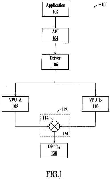
Sheet 1 of 17 from the published document. All sheets in the USPTO PDF
A system and method are disclosed for selectively focusing on certain areas of interest within an imaged scene to gain more image detail within those areas. In general, the present system identifies areas of interest from received image data, which may for example be detected areas of movement within the scene. The system then focuses on those areas by providing more detail in the area of interest. This may be accomplished by a number of methods, including zooming in on the image, increasing pixel density of the image and increasing the amount of light incident on the object in the image.
In the past, computing applications such as computer games and multimedia applications used controllers, remotes, keyboards, mice, or the like to allow users to manipulate game characters or other aspects of an application. More recently, computer games and multimedia applications have begun employing cameras and software gesture recognition engines to provide a natural user interface ("NUI"). With NUI, user gestures are detected, interpreted and used to control game characters or other aspects of an application. At times, activity may be occurring within a small portion of the entire field of view. For example, a single user may be standing in a large room of stationary objects. Or a user may only be using his hand in making gestures such as controlling a user interface or performing sign language. However, conventional NUI systems process all information from a scene in the same way, r
1 of 17 drawing sheets so far from the published document, cropped to the drawing. Every sheet is in the USPTO PDF.
What the patent claimed, word for word. All of it is now free to use.
In the past, computing applications such as computer games and multimedia applications used controllers, remotes, keyboards, mice, or the like to allow users to manipulate game characters or other aspects of an application. More recently, computer games and multimedia applications have begun employing cameras and software gesture recognition engines to provide a natural user interface ("NUI"). With NUI, user gestures are detected, interpreted and used to control game characters or other aspects of an application.
At times, activity may be occurring within a small portion of the entire field of view. For example, a single user may be standing in a large room of stationary objects. Or a user may only be using his hand in making gestures such as controlling a user interface or performing sign language. However, conventional NUI systems process all information from a scene in the same way, regardless of whether it is static or dynamic. There is therefore a need for a system which focuses greater attention on the dynamic areas of a field of view than on the static areas of the field of view.
Disclosed herein are systems and methods for selectively focusing on certain areas of interest within an imaged scene to gain more image detail within those areas. In general, the present system identifies areas of interest from received image data, which may for example be detected areas of movement within the scene. The system then focuses on those areas by providing more detail in the area of interest. This may be accomplished by a number of methods, such as for example a mechanical or digital zoom to the area, increasing the pixel density in the area, decreasing pixel density outside of the area and increasing the amount of light incident on the area. In order to process the image data within given frame rates, the areas of the image outside of the area of interest may be stored in a buffer and re-used if needed, together with the image data from the area of interest, to render an image of the scene.
In an embodiment, the present technology relates to a method of increasing image detail in one or more areas of interest in a scene captured by a capture device. The method includes the steps of: a) receiving information from the scene; b) identifying the one or more areas of interest within the scene; c) obtaining greater image detail on the one or more areas of interest within the scene relative to areas in the scene outside of the one or more areas of interest; and d) at least periodically monitoring information in the scene outside the one or more areas of interest to determine whether to re-define the one or more areas of interest.
In a further embodiment, the present technology relates to a method of increasing image detail in one or more areas of interest in a scene captured by a capture device, including the steps of: a) defining a zone of focus within the scene, the zone of focus defined to correspond with one or more expected areas of interest within the scene; and b) obtaining greater image detail on the zone of focus within the scene relative to areas in the scene outside of the one or more areas of interest.
In a further embodiment, the present technology relates to a method of increasing image detail in one or more areas of interest in a scene captured by a capture device. The method includes the steps of: a) receiving information from the scene; b) identifying one or more users within the scene; c) obtaining greater image detail on at least a body part of the one or more users within the scene relative to areas in the scene other than the one or more users; d) using the greater image detail obtained on at least the body part of the one or more users within the scene in said step c) to identify a gesture performed by the one or more users; and e) at least periodically monitoring information in the scene outside the one or more users to determine whether to add or subtract a user to the group of one or more users on which greater image detail is obtained in said step c).
This Summary is provided to introduce a selection of concepts in a simplified form that are further described below in the Detailed Description. This Summary is not intended to identify key features or essential features of the claimed subject matter, nor is it intended to be used as an aid in determining the scope of the claimed subject matter. Furthermore, the claimed subject matter is not limited to implementations that solve any or all disadvantages noted in any part of this disclosure.
FIG. 1A illustrates an example embodiment of a target recognition, analysis, and tracking system.
FIG. 1B illustrates a further example embodiment of a target recognition, analysis, and tracking system.
FIG. 2 illustrates an example embodiment of a capture device that may be used in a target recognition, analysis, and tracking system.
FIG. 3A illustrates an example embodiment of a computing environment that may be used to interpret one or more gestures in a target recognition, analysis, and tracking system.
FIG. 3B illustrates another example embodiment of a computing environment that may be used to interpret one or more gestures in a target recognition, analysis, and tracking system.
FIG. 4 illustrates a skeletal mapping of a user that has been generated from the target recognition, analysis, and tracking system of FIGS. 1A-2.
FIG. 5 is an illustration of a pixilated image of a scene captured by a capture device.
FIG. 6 is an illustration of a pixilated image showing greater focus on an area of interest in a scene captured by a capture device.
FIG. 6A is an illustration of an alternative pixilated image showing greater focus on an area of interest in a scene captured by a capture device
FIG. 7 is an illustration of a pixilated image showing greater focus on an alternative area of interest in a scene captured by a capture device.
FIG. 8 is an illustration showing a pair of pixilated images of two areas of interest from a scene captured by a capture device.
FIG. 9 is an illustration showing a pixilated image having an increased pixel density in an area of interest in the scene captured by a capture device.
FIG. 10 is an illustration showing a zone of focus within an image of a scene captured by a capture device.
FIG. 11 is a flowchart of the operation of one embodiment of the present technology for focusing an image on an area of interest within a scene.
FIG. 12 is a flowchart of the operation of a further embodiment of the present technology for focusing an image on an area of interest within a scene by increasing pixel density in that area.
FIG. 13 is a flowchart of the operation of another embodiment of the present technology for passively increasing focus in a zone of focus on an area of interest in a scene.
FIG. 14 is a flowchart of the operation of a further embodiment of the present technology for increasing the amount of light incident on objects within an area of interest in a scene.
FIG. 15 is a flowchart of the operation of another embodiment of the present technology for passively increasing the amount of light incident on objects within an area of interest in a scene.
FIG. 16 is a block diagram showing a gesture recognition engine for recognizing gestures.
FIG. 17 is a flowchart of the operation of the gesture recognition engine of FIGS. 16.
Embodiments of the present technology will now be described with reference to FIGS. 1A-17, which in general relate to a system and method for selectively focusing on certain areas of interest within an imaged scene to gain more image detail within those areas. In general, the present system identifies areas of interest from received image data, which may for example be detected areas of movement within the scene. The system then focuses on those areas by providing more detail in the area of interest. This may be accomplished by a number of methods, including zooming in on the image, increasing pixel density of the image and increasing the amount of light incident on the object in the image.
Referring initially to FIGS. 1A-2, the hardware for implementing the present technology includes a target recognition, analysis, and tracking system 10 which may be used to recognize, analyze, and/or track a human target such as the user 18. Embodiments of the target recognition, analysis, and tracking system 10 include a computing environment 12 for executing a gaming or other application. The computing environment 12 may include hardware components and/or software components such that computing environment 12 may be used to execute applications such as gaming and non-gaming applications. In one embodiment, computing environment 12 may include a processor such as a standardized processor, a specialized processor, a microprocessor, or the like that may execute instructions stored on a processor readable storage device for performing processes described herein.
The system 10 further includes a capture device 20 for capturing image and audio data relating to one or more users and/or objects sensed by the capture device. In embodiments, the capture device 20 may be used to capture information relating to movements, gestures and speech of one or more users, which information is received by the computing environment and used to render, interact with and/or control aspects of a gaming or other application. Examples of the computing environment 12 and capture device 20 are explained in greater detail below.
Embodiments of the target recognition, analysis, and tracking system 10 may be connected to an audio/visual device 16 having a display 14. The device 16 may for example be a television, a monitor, a high-definition television (HDTV), or the like that may provide game or application visuals and/or audio to a user. For example, the computing environment 12 may include a video adapter such as a graphics card and/or an audio adapter such as a sound card that may provide audio/visual signals associated with the game or other application. The audio/visual device 16 may receive the audio/visual signals from the computing environment 12 and may then output the game or application visuals and/or audio associated with the audio/visual signals to the user 18. According to one embodiment, the audio/visual device 16 may be connected to the computing environment 12 via, for example, an S-Video cable, a coaxial cable, an HDMI cable, a DVI cable, a VGA cable, a component video cable, or the like.
In embodiments, the computing environment 12, the A/V device 16 and the capture device 20 may cooperate to render an avatar or on-screen character 19 on display 14. In embodiments, the avatar 19 mimics the movements of the user 18 in real world space so that the user 18 may perform movements and gestures which control the movements and actions of the avatar 19 on the display 14.
In FIG. 1A, the capture device 20 is used in a NUI system where for example a pair of users 18 are playing a soccer game. In this example, the computing environment 12 may use the audiovisual display 14 to provide a visual representation of two avatars 19 in the form of soccer players controlled by the respective users 18. A user 18 may move or perform a kicking motion in physical space to cause their associated player avatar 19 to move or kick the soccer ball in game space. Thus, according to an example embodiment, the computing environment 12 and the capture device 20 may be used to recognize and analyze movements and gestures of the users 18 in physical space, and such movements and gestures may be interpreted as a game control or action of the user's associated avatar 19 in game space.
The embodiment of FIG. 1A is one of many different applications which may be run on computing environment 12, and the application running on computing environment 12 may be a variety of other gaming and non-gaming applications. Moreover, the system 10 may further be used to interpret user 18 movements as operating system (OS) and/or application controls that are outside the realm of games or the specific application running on computing environment 12. One example is shown in FIG. 1B, where a user 18 is scrolling through and controlling a user interface 21 with a variety of menu options presented on the display 14. Virtually any controllable aspect of an operating system and/or application may be controlled by the movements of the user 18.
Both FIGS. 1A and 1B further show static objects 23, such as the chair and plant. These are objects within the scene (i.e., the area captured by capture device 20), but do not change from frame to frame. In addition to the chair and plant shown, static objects may be any objects picked up by the image cameras in capture device 20. The additional static objects within the scene may include any walls, floor, ceiling, windows, doors, wall decorations, etc.
Suitable examples of a system 10 and components thereof are found in the following co-pending patent applications, all of which are hereby specifically incorporated by reference: U.S. patent application Ser. No. 12/475,094, entitled "Environment And/Or Target Segmentation," filed May 29, 2009; U.S. patent application Ser. No. 12/511,850, entitled "Auto Generating a Visual Representation," filed Jul. 29, 2009; U.S. patent application Ser. No. 12/474,655, entitled "Gesture Tool," filed May 29, 2009; U.S. patent application Ser. No. 12/603,437, entitled "Pose Tracking Pipeline," filed Oct. 21, 2009; U.S. patent application Ser. No. 12/475,308, entitled "Device for Identifying and Tracking Multiple Humans Over Time," filed May 29, 2009, U.S. patent application Ser. No. 12/575,388, entitled "Human Tracking System," filed Oct. 7, 2009; U.S. patent application Ser. No. 12/422,661, entitled "Gesture Recognizer System Architecture," filed Apr. 13, 2009; U.S. patent application Ser. No. 12/391,150, entitled "Standard Gestures," filed Feb. 23, 2009; and U.S. patent application Ser. No. 12/474,655, entitled "Gesture Tool," filed May 29, 2009.
FIG. 2 illustrates an example embodiment of the capture device 20 that may be used in the target recognition, analysis, and tracking system 10. In an example embodiment, the capture device 20 may be configured to capture video having a depth image that may include depth values via any suitable technique including, for example, time-of-flight, structured light, stereo image, or the like. According to one embodiment, the capture device 20 may organize the calculated depth information into "Z layers," or layers that may be perpendicular to a Z axis extending from the depth camera along its line of sight.
As shown in FIG. 2, the capture device 20 may include an image camera component 22. According to an example embodiment, the image camera component 22 may be a depth camera that may capture the depth image of a scene. The depth image may include a two-dimensional (2-D) pixel area of the captured scene where each pixel in the 2-D pixel area may represent a depth value such as a length or distance in, for example, centimeters, millimeters, or the like of an object in the captured scene from the camera.
As shown in FIG. 2, according to an example embodiment, the image camera component 22 may include an IR light component 24, a three-dimensional (3-D) camera 26, and an RGB camera 28 that may be used to capture the depth image of a scene. For example, in time-of-flight analysis, the IR light component 24 of the capture device 20 may emit an infrared light onto the scene and may then use sensors (not shown) to detect the backscattered light from the surface of one or more targets and objects in the scene using, for example, the 3-D camera 26 and/or the RGB camera 28.
In some embodiments, pulsed infrared light may be used such that the time between an outgoing light pulse and a corresponding incoming light pulse may be measured and used to determine a physical distance from the capture device 20 to a particular location on the targets or objects in the scene. Additionally, in other example embodiments, the phase of the outgoing light wave may be compared to the phase of the incoming light wave to determine a phase shift. The phase shift may then be used to determine a physical distance from the capture device 20 to a particular location on the targets or objects.
According to another example embodiment, time-of-flight analysis may be used to indirectly determine a physical distance from the capture device 20 to a particular location on the targets or objects by analyzing the intensity of the reflected beam of light over time via various techniques including, for example, shuttered light pulse imaging.
In another example embodiment, the capture device 20 may use a structured light to capture depth information. In such an analysis, patterned light (i.e., light displayed as a known pattern such as grid pattern or a stripe pattern) may be projected onto the scene via, for example, the IR light component 24. Upon striking the surface of one or more targets or objects in the scene, the pattern may become deformed in response. Such a deformation of the pattern may be captured by, for example, the 3-D camera 26 and/or the RGB camera 28 and may then be analyzed to determine a physical distance from the capture device 20 to a particular location on the targets or objects.
According to another embodiment, the capture device 20 may include two or more physically separated cameras that may view a scene from different angles, to obtain visual stereo data that may be resolved to generate depth information. In another example embodiment, the capture device 20 may use point cloud data and target digitization techniques to detect features of the user 18.
The capture device 20 may further include a microphone 30. The microphone 30 may include a transducer or sensor that may receive and convert sound into an electrical signal. According to one embodiment, the microphone 30 may be used to reduce feedback between the capture device 20 and the computing environment 12 in the target recognition, analysis, and tracking system 10. Additionally, the microphone 30 may be used to receive audio signals that may also be provided by the user to control applications such as game applications, non-game applications, or the like that may be executed by the computing environment 12.
In an example embodiment, the capture device 20 may further include a processor 32 that may be in operative communication with the image camera component 22. The processor 32 may include a standardized processor, a specialized processor, a microprocessor, or the like that may execute instructions that may include instructions for receiving the depth image, determining whether a suitable target may be included in the depth image, converting the suitable target into a skeletal representation or model of the target, or any other suitable instruction.
The capture device 20 may further include a memory component 34 that may store the instructions that may be executed by the processor 32, images or frames of images captured by the 3-D camera or RGB camera, or any other suitable information, images, or the like. According to an example embodiment, the memory component 34 may include random access memory (RAM), read only memory (ROM), cache, Flash memory, a hard disk, or any other suitable storage component. As shown in FIG. 2, in one embodiment, the memory component 34 may be a separate component in communication with the image camera component 22 and the processor 32. According to another embodiment, the memory component 34 may be integrated into the processor 32 and/or the image camera component 22.
As shown in FIG. 2, the capture device 20 may be in communication with the computing environment 12 via a communication link 36. The communication link 36 may be a wired connection including, for example, a USB connection, a Firewire connection, an Ethernet cable connection, or the like and/or a wireless connection such as a wireless 802.11b, g, a, or n connection. According to one embodiment, the computing environment 12 may provide a clock to the capture device 20 that may be used to determine when to capture, for example, a scene via the communication link 36.
Additionally, the capture device 20 may provide the depth information and images captured by, for example, the 3-D camera 26 and/or the RGB camera 28, and a skeletal model that may be generated by the capture device 20 to the computing environment 12 via the communication link 36. A variety of known techniques exist for determining whether a target or object detected by capture device 20 corresponds to a human target. Skeletal mapping techniques may then be used to determine various spots on that user's skeleton, joints of the hands, wrists, elbows, knees, nose, ankles, shoulders, and where the pelvis meets the spine. Other techniques include transforming the image into a body model representation of the person and transforming the image into a mesh model representation of the person.
The skeletal model may then be provided to the computing environment 12 such that the computing environment may perform a variety of actions. The computing environment may further determine which controls to perform in an application executing on the computer environment based on, for example, gestures of the user that have been recognized from the skeletal model. For example, as shown, in FIG. 2, the computing environment 12 may include a gesture recognizer engine 190 for determining when the user has performed a predefined gesture. The computing environment 12 may further include a focus engine 192 for focusing on interesting areas from a scene as explained below. Portions, or all, of the focus engine 192 may be resident on capture device 20 and executed by the processor 32.
FIG. 3A illustrates an example embodiment of a computing environment that may be used to interpret one or more positions and motions of a user in a target recognition, analysis, and tracking system. The computing environment such as the computing environment 12 described above with respect to FIGS. 1A-2 may be a multimedia console 100, such as a gaming console. As shown in FIG. 3A, the multimedia console 100 has a central processing unit (CPU) 101 having a level 1 cache 102, a level 2 cache 104, and a flash ROM 106. The level 1 cache 102 and a level 2 cache 104 temporarily store data and hence reduce the number of memory access cycles, thereby improving processing speed and throughput. The CPU 101 may be provided having more than one core, and thus, additional level 1 and level 2 caches 102 and 104. The flash ROM 106 may store executable code that is loaded during an initial phase of a boot process when the multimedia console 100 is powered ON.
A graphics processing unit (GPU) 108 and a video encoder/video codec (coder/decoder) 114 form a video processing pipeline for high speed and high resolution graphics processing. Data is carried from the GPU 108 to the video encoder/video codec 114 via a bus. The video processing pipeline outputs data to an A/V (audio/video) port 140 for transmission to a television or other display. A memory controller 110 is connected to the GPU 108 to facilitate processor access to various types of memory 112, such as, but not limited to, a RAM.
The multimedia console 100 includes an I/O controller 120, a system management controller 122, an audio processing unit 123, a network interface controller 124, a first USB host controller 126, a second USB host controller 128 and a front panel I/O subassembly 130 that are preferably implemented on a module 118. The USB controllers 126 and 128 serve as hosts for peripheral controllers 142(1)-142(2), a wireless adapter 148, and an external memory device 146 (e.g., flash memory, external CD/DVD ROM drive, removable media, etc.). The network interface 124 and/or wireless adapter 148 provide access to a network (e.g., the Internet, home network, etc.) and may be any of a wide variety of various wired or wireless adapter components including an Ethernet card, a modem, a Bluetooth module, a cable modem, and the like.
System memory 143 is provided to store application data that is loaded during the boot process. A media drive 144 is provided and may comprise a DVD/CD drive, hard drive, or other removable media drive, etc. The media drive 144 may be internal or external to the multimedia console 100. Application data may be accessed via the media drive 144 for execution, playback, etc. by the multimedia console 100. The media drive 144 is connected to the I/O controller 120 via a bus, such as a Serial ATA bus or other high speed connection (e.g., IEEE 1394).
The system management controller 122 provides a variety of service functions related to assuring availability of the multimedia console 100. The audio processing unit 123 and an audio codec 132 form a corresponding audio processing pipeline with high fidelity and stereo processing. Audio data is carried between the audio processing unit 123 and the audio codec 132 via a communication link. The audio processing pipeline outputs data to the AN port 140 for reproduction by an external audio player or device having audio capabilities.
The front panel I/O subassembly 130 supports the functionality of the power button 150 and the eject button 152, as well as any LEDs (light emitting diodes) or other indicators exposed on the outer surface of the multimedia console 100. A system power supply module 136 provides power to the components of the multimedia console 100. A fan 138 cools the circuitry within the multimedia console 100.
The CPU 101, GPU 108, memory controller 110, and various other components within the multimedia console 100 are interconnected via one or more buses, including serial and parallel buses, a memory bus, a peripheral bus, and a processor or local bus using any of a variety of bus architectures. By way of example, such architectures can include a Peripheral Component Interconnects (PCI) bus, PCI-Express bus, etc.
When the multimedia console 100 is powered ON, application data may be loaded from the system memory 143 into memory 112 and/or caches 102, 104 and executed on the CPU 101. The application may present a graphical user interface that provides a consistent user experience when navigating to different media types available on the multimedia console 100. In operation, applications and/or other media contained within the media drive 144 may be launched or played from the media drive 144 to provide additional functionalities to the multimedia console 100.
The multimedia console 100 may be operated as a standalone system by simply connecting the system to a television or other display. In this standalone mode, the multimedia console 100 allows one or more users to interact with the system, watch movies, or listen to music. However, with the integration of broadband connectivity made available through the network interface 124 or the wireless adapter 148, the multimedia console 100 may further be operated as a participant in a larger network community.
When the multimedia console 100 is powered ON, a set amount of hardware resources are reserved for system use by the multimedia console operating system. These resources may include a reservation of memory (e.g., 16 MB), CPU and GPU cycles (e.g., 5%), networking bandwidth (e.g., 8 kbs), etc. Because these resources are reserved at system boot time, the reserved resources do not exist from the application's view.
In particular, the memory reservation preferably is large enough to contain the launch kernel, concurrent system applications and drivers. The CPU reservation is preferably constant such that if the reserved CPU usage is not used by the system applications, an idle thread will consume any unused cycles.
With regard to the GPU reservation, lightweight messages generated by the system applications (e.g., popups) are displayed by using a GPU interrupt to schedule code to render popup into an overlay. The amount of memory required for an overlay depends on the overlay area size and the overlay preferably scales with screen resolution. Where a full user interface is used by the concurrent system application, it is preferable to use a resolution independent of the application resolution. A scaler may be used to set this resolution such that the need to change frequency and cause a TV resynch is eliminated.
After the multimedia console 100 boots and system resources are reserved, concurrent system applications execute to provide system functionalities. The system functionalities are encapsulated in a set of system applications that execute within the reserved system resources described above. The operating system kernel identifies threads that are system application threads versus gaming application threads. The system applications are preferably scheduled to run on the CPU 101 at predetermined times and intervals in order to provide a consistent system resource view to the application. The scheduling is to minimize cache disruption for the gaming application running on the console.
When a concurrent system application requires audio, audio processing is scheduled asynchronously to the gaming application due to time sensitivity. A multimedia console application manager (described below) controls the gaming application audio level (e.g., mute, attenuate) when system applications are active.
Input devices (e.g., controllers 142
and 142(2)) are shared by gaming applications and system applications. The input devices are not reserved resources, but are to be switched between system applications and the gaming application such that each will have a focus of the device. The application manager preferably controls the switching of input stream, without knowledge of the gaming application's knowledge and a driver maintains state information regarding focus switches. The cameras 26, 28 and capture device 20 may define additional input devices for the console 100.
FIG. 3B illustrates another example embodiment of a computing environment 220 that may be the computing environment 12 shown in FIGS. 1A-2 used to interpret one or more positions and motions in a target recognition, analysis, and tracking system. The computing system environment 220 is only one example of a suitable computing environment and is not intended to suggest any limitation as to the scope of use or functionality of the presently disclosed subject matter. Neither should the computing environment 220 be interpreted as having any dependency or requirement relating to any one or combination of components illustrated in the exemplary operating environment 220. In some embodiments, the various depicted computing elements may include circuitry configured to instantiate specific aspects of the present disclosure. For example, the term circuitry used in the disclosure can include specialized hardware components configured to perform function(s) by firmware or switches. In other example embodiments, the term circuitry can include a general purpose processing unit, memory, etc., configured by software instructions that embody logic operable to perform function(s). In example embodiments where circuitry includes a combination of hardware and software, an implementer may write source code embodying logic and the source code can be compiled into machine readable code that can be processed by the general purpose processing unit. Since one skilled in the art can appreciate that the state of the art has evolved to a point where there is little difference between hardware, software, or a combination of hardware/software, the selection of hardware versus software to effectuate specific functions is a design choice left to an implementer. More specifically, one of skill in the art can appreciate that a software process can be transformed into an equivalent hardware structure, and a hardware structure can itself be transformed into an equivalent software process. Thus, the selection of a hardware implementation versus a software implementation is one of design choice and left to the implementer.
In FIG. 3B, the computing environment 220 comprises a computer 241, which typically includes a variety of computer readable media. Computer readable media can be any available media that can be accessed by computer 241 and includes both volatile and nonvolatile media, removable and non-removable media. The system memory 222 includes computer storage media in the form of volatile and/or nonvolatile memory such as ROM 223 and RAM 260. A basic input/output system 224 (BIOS), containing the basic routines that help to transfer information between elements within computer 241, such as during start-up, is typically stored in ROM 223. RAM 260 typically contains data and/or program modules that are immediately accessible to and/or presently being operated on by processing unit 259. By way of example, and not limitation, FIG. 3B illustrates operating system 225, application programs 226, other program modules 227, and program data 228. FIG. 3B further includes a graphics processor unit (GPU) 229 having an associated video memory 230 for high speed and high resolution graphics processing and storage. The GPU 229 may be connected to the system bus 221 through a graphics interface 231.
The computer 241 may also include other removable/non-removable, volatile/nonvolatile computer storage media. By way of example only, FIG. 3B illustrates a hard disk drive 238 that reads from or writes to non-removable, nonvolatile magnetic media, a magnetic disk drive 239 that reads from or writes to a removable, nonvolatile magnetic disk 254, and an optical disk drive 240 that reads from or writes to a removable, nonvolatile optical disk 253 such as a CD ROM or other optical media. Other removable/non-removable, volatile/nonvolatile computer storage media that can be used in the exemplary operating environment include, but are not limited to, magnetic tape cassettes, flash memory cards, digital versatile disks, digital video tape, solid state RAM, solid state ROM, and the like. The hard disk drive 238 is typically connected to the system bus 221 through a non-removable memory interface such as interface 234, and magnetic disk drive 239 and optical disk drive 240 are typically connected to the system bus 221 by a removable memory interface, such as interface 235.
The drives and their associated computer storage media discussed above and illustrated in FIG. 3B, provide storage of computer readable instructions, data structures, program modules and other data for the computer 241. In FIG. 3B, for example, hard disk drive 238 is illustrated as storing operating system 258, application programs 257, other program modules 256, and program data 255. Note that these components can either be the same as or different from operating system 225, application programs 226, other program modules 227, and program data 228. Operating system 258, application programs 257, other program modules 256, and program data 255 are given different numbers here to illustrate that, at a minimum, they are different copies. A user may enter commands and information into the computer 241 through input devices such as a keyboard 251 and a pointing device 252, commonly referred to as a mouse, trackball or touch pad. Other input devices (not shown) may include a microphone, joystick, game pad, satellite dish, scanner, or the like. These and other input devices are often connected to the processing unit 259 through a user input interface 236 that is coupled to the system bus, but may be connected by other interface and bus structures, such as a parallel port, game port or a universal serial bus (USB). The cameras 26, 28 and capture device 20 may define additional input devices for the console 100. A monitor 242 or other type of display device is also connected to the system bus 221 via an interface, such as a video interface 232. In addition to the monitor, computers may also include other peripheral output devices such as speakers 244 and printer 243, which may be connected through an output peripheral interface 233.
The computer 241 may operate in a networked environment using logical connections to one or more remote computers, such as a remote computer 246. The remote computer 246 may be a personal computer, a server, a router, a network PC, a peer device or other common network node, and typically includes many or all of the elements described above relative to the computer 241, although only a memory storage device 247 has been illustrated in FIG. 3B. The logical connections depicted in FIG. 3B include a local area network (LAN) 245 and a wide area network (WAN) 249, but may also include other networks. Such networking environments are commonplace in offices, enterprise-wide computer networks, intranets and the Internet.
When used in a LAN networking environment, the computer 241 is connected to the LAN 245 through a network interface or adapter 237. When used in a WAN networking environment, the computer 241 typically includes a modem 250 or other means for establishing communications over the WAN 249, such as the Internet. The modem 250, which may be internal or external, may be connected to the system bus 221 via the user input interface 236, or other appropriate mechanism. In a networked environment, program modules depicted relative to the computer 241, or portions thereof, may be stored in the remote memory storage device. By way of example, and not limitation, FIG. 3B illustrates remote application programs 248 as residing on memory device 247. It will be appreciated that the network connections shown are exemplary and other means of establishing a communications link between the computers may be used.
FIG. 4 depicts an example skeletal mapping of a user that may be generated from the capture device 20. In this embodiment, a variety of joints and bones are identified: each hand 302, each forearm 304, each elbow 306, each bicep 308, each shoulder 310, each hip 312, each thigh 314, each knee 316, each foreleg 318, each foot 320, the head 322, the torso 324, the top 326 and the bottom 328 of the spine, and the waist 330. Where more points are tracked, additional features may be identified, such as the bones and joints of the fingers or toes, or individual features of the face, such as the nose and eyes.
As indicated in the Background section, it may at times be desirable to obtain more detailed image data from certain objects in a scene without introducing latency into the rendering of images. In accordance with aspects of the present technology, areas of interest may be identified within a scene, and those areas may be focused on to obtain greater image detail from those areas.
FIG. 5 shows an image as detected by the sensors of the image camera component 22 of capture device 20. It may for example be the user interacting with the onscreen user interface as shown in FIG. 1B. The image is broken down into a lattice of horizontal rows and vertical columns of pixels 350 (some of which are numbered in the figures). Where image camera component 22 is a depth camera 26, each pixel in the lattice captures an x, y and z location of objects in the scene, where a z-axis is defined straight out from a camera lens, and the x-axis and y-axis are horizontal and vertical offsets, respectively, from the z-axis. Where camera component 22 is an RGB camera 28, each pixel in the lattice captures an RGB value of objects in the scene. The RGB camera is registered to the depth camera so that each frame captured by the cameras 24 and 26 are time synchronized to each other. The scene of FIG. 5 shows the user 18 and stationary objects 23 such as a chair and plant, which are captured by the pixels 350. The image detail in the scene is evenly distributed across all pixels 350.
The description continues in the full USPTO document.
About 6,591 words. The USPTO PDF has it with every drawing.
Fees are due 3.5, 7.5 and 11.5 years after grant. This patent expired on February 18, 2026, so the fee marked "not paid" was the one that went unpaid.
COMPARTMENTALIZING FOCUS AREA WITHIN FIELD OF VIEW
Filed Jun 2010 · published Dec 2011Compartmentalizing focus area within field of view
Filed Jun 2010 · granted Feb 2014Earlier publications, parents and continuations. None of them can still be enforced, or this patent would not be listed.
Prior art cited by the examiner or applicant. Useful when you check your own idea for novelty.
Everything on this page comes from the documents linked above.