Background of the invention
1. Field of the invention
The present invention relates to a grasping treatment device configured to perform a treatment by grasping a grasping target such as a living tissue between the distal portion of a probe and a jaw configured to open/close relative to the distal portion of the probe.
2. Description of the related art
Jpn. PCT National Publication No. 2009-514566 has disclosed an ultrasonic device, which is a grasping treatment device, including a probe configured to transmit ultrasonic waves, and a jaw configured to open/close relative to the distal portion of the probe. In this ultrasonic device, a scissors-like handle unit is opened/closed to grasp a grasping target such as a living tissue between the distal portion of the probe and the jaw, and thereby performs a treatment of the grasping target.
Jpn. Pat. Appln. KOKAI Publication No. 2009-261911 has disclosed an ultrasonic coagulation-and-cutting device, which is a grasping treatment device, including a probe configured to transmit ultrasonic waves and a jaw configured to open/close relative to the distal portion of the probe. This ultrasonic coagulation-and-cutting device is also used as a bipolar treatment device, which uses the distal portion of the probe as a first electrode portion and the jaw as a second electrode portion, to perform a bipolar treatment by a high-frequency current between the distal portion of the probe and the jaw. In this ultrasonic coagulation-and-cutting device, the jaw includes a jaw body rotatably attached to a sheath, and a wiper member attached to the jaw body via a pin. The wiper member is rotatable relative to the jaw body around the pin.
Brief summary of the invention
According to one aspect of the invention, a grasping treatment device includes that a probe extending along a longitudinal axis; a sheath through which the probe is inserted so that the probe protrudes toward a distal direction; a jaw which is attached to a distal portion of the sheath rotatably around a rotation axis perpendicular to the longitudinal axis, and which is configured to open/close relative to a distal portion of the probe in open/close directions perpendicular to the longitudinal axis and perpendicular to the rotation axis; and a support member which is provided between the probe and the sheath, and which is configured to prevent contact between the probe and the sheath, wherein the support member includes a most-distal support member which is located on the most distal direction side, the position of the most-distal support member coinciding with the rotation axis of the jaw in directions parallel to the longitudinal axis.
Advantages of the invention will be set forth in the description which follows, and in part will be obvious from the description, or may be learned by practice of the invention. The advantages of the invention may be realized and obtained by means of the instrumentalities and combinations particularly pointed out hereinafter.
Brief description of the several views of the drawing
The accompanying drawings, which are incorporated in and constitute a part of the specification, illustrate embodiments of the invention, and together with the general description given above and the detailed description of the embodiments given below, serve to explain the principles of the invention.
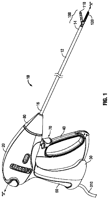
FIG. 1 is a schematic diagram showing a medical treatment device according to a first embodiment of the present invention;
FIG. 2 is a schematic sectional view showing the configuration of a vibrator unit according to the first embodiment;
FIG. 3 is a partially sectional schematic side view showing the configuration of a probe according to the first embodiment;
FIG. 4 is a schematic sectional view showing the configuration of the inside of a fixed handle according to the first embodiment;
FIG. 5 is a schematic diagram showing the electric connection between a vibrator case, a cylindrical member, and an electric connection ring according to the first embodiment;
FIG. 6 is a schematic sectional view showing a state in which the probe is inserted through a sheath according to the first embodiment;
FIG. 7 is a sectional view taken along the line VII-VII of FIG. 6;
FIG. 8 is a schematic diagram showing a state in which a jaw is in abutment with a first electrode portion of the probe according to the first embodiment;
FIG. 9 is a schematic diagram showing a state in which a probe facing portion of the jaw and a jaw facing portion of the probe according to the first embodiment are parallel to each other;
FIG. 10 is a schematic sectional view showing the configurations of a first groove defining portion and a first projection of an electric contact unit according to the first embodiment;
FIG. 11 is a schematic sectional view showing the sheath and the jaw when the jaw is not attached to the sheath according to the first embodiment;
FIG. 12 is a schematic diagram showing a state in which an operator grasps the fixed handle and a movable handle during a treatment with the medical treatment device according to the first embodiment;
FIG. 13 is a schematic diagram showing a state in which a jaw is in abutment with a first electrode portion of a probe according to a first comparative example;
FIG. 14 is a schematic diagram showing a state in which probe facing portion of a jaw and a jaw facing portion of the probe according to a second comparative example are parallel to each other;
FIG. 15 is a schematic diagram showing a state in which a living tissue is grasped between the jaw and a first electrode portion of the probe according to the second comparative example;
FIG. 16 is a schematic diagram showing a state in which the living tissue is grasped between the jaw and the first electrode portion of the probe according to the first embodiment;
FIG. 17 is a schematic side view showing a fixed handle and the movable handle according to a third comparative example;
FIG. 18 is a schematic side view showing a fixed handle and the movable handle according to a fourth comparative example;
FIG. 19 is a schematic sectional view showing the configuration of an electric contact unit according to a fifth comparative example;
FIG. 20 is a schematic sectional view showing the configuration of an electric contact unit according to a sixth comparative example;
FIG. 21 is a schematic sectional view showing the configurations of the first groove defining portion and the first projection of the electric contact unit according to a first modification;
FIG. 22 is a schematic sectional view showing the configurations of the first groove defining portion and the first projection of the electric contact unit according to a second modification;
FIG. 23 is a schematic sectional view showing the configurations of the first groove defining portion and the first projection of the electric contact unit according to a third modification;
FIG. 24 is a schematic sectional view showing the configuration of the electric contact unit according to a fourth modification;
FIG. 25 is a schematic sectional view showing the configurations of the first groove defining portion and the first projection of the electric contact unit according to the fourth modification;
FIG. 26 is a schematic sectional view showing the sheath and the jaw when the jaw is not attached to the sheath according to the fourth modification;
FIG. 27A is a schematic sectional view showing the configurations of the first groove defining portion and the first projection of the electric contact unit according to a fifth modification;
FIG. 27B is a schematic sectional view showing the configuration of the inside of the fixed handle according to a sixth modification;
FIG. 28 is a schematic diagram showing a medical treatment device according to a first referential example;
FIG. 29 is a schematic sectional view showing the configurations of a probe and a sheath unit according to the first referential example;
FIG. 30 is a schematic perspective view showing the configuration of a jaw according to the first referential example;
FIG. 31A is a schematic perspective view showing the configuration of a jaw body of the jaw according to the first referential example;
FIG. 31B is a schematic perspective view showing the configuration of an elastic member of the jaw according to the first referential example;
FIG. 32 is a schematic perspective view showing the configuration of a probe protecting member according to the first referential example;
FIG. 33 is a sectional view taken along the line 33-33 of FIG. 29;
FIG. 34 is a schematic perspective view showing the configuration of a support member according to the first referential example; and
FIG. 35 is a schematic perspective view showing the configuration of the support member according to a second referential example.
Detailed description of the invention
First Embodiment
A first embodiment of the present invention is described with reference to FIG. 1 to FIG. 20. FIG. 1 is a diagram showing a medical treatment device 1 according to the present embodiment. This medical treatment device 1 is a grasping treatment device which is configured to grasp a grasping target such as a living tissue between a distal portion of a probe 3 (described later) and a jaw 52 (described later) and configured to treat the grasped grasping target using an energy such as ultrasonic waves, high-frequency waves, or heat. The medical treatment device 1 according to the present embodiment is used as a bipolar treatment device which is configured to use the distal portion of the probe 3 and the jaw 52 as electrodes to perform a treatment by a high-frequency current. The medical treatment device 1 is also used as an ultrasonic treatment device which is configured to perform a treatment by ultrasonic vibrations. As shown in FIG. 1, the medical treatment device 1 includes a vibrator unit 2, the probe 3, a sheath unit 4, and a movable handle unit 5.
The vibrator unit 2 includes a vibrator case 11. One end of a cable 6 is connected to a proximal end of the vibrator case 11. The other end of the cable 6 is connected to a power supply unit 7. The power supply unit 7 includes an ultrasonic controller 8 and a high-frequency current controller 9.
FIG. 2 is a diagram showing the configuration of the vibrator unit 2. As shown in FIG. 2, an ultrasonic vibrator 12, which includes a piezoelectric element configured to convert a current to ultrasonic vibrations, is provided inside the vibrator case 11. One end of each of electric signal lines 13A and 13B is connected to the ultrasonic vibrator 12. The other end of each of the electric signal lines 13A and 13B is connected to the ultrasonic controller 8 of the power supply unit 7 through the cable 6. Ultrasonic vibrations are generated in the ultrasonic vibrator 12 by supplying a current to the ultrasonic vibrator 12 from the ultrasonic controller 8 via the electric signal lines 13A and 13B. A horn 15, which is configured to increase the amplitude of the ultrasonic vibrations, is coupled to a distal direction side of the ultrasonic vibrator 12.
The horn 15 is attached to the vibrator case 11, and electrically insulated from the vibrator case 11. An internal thread 16 is formed in a distal portion of the horn 15. In addition to the electric signal lines 13A and 13B, an electric signal line 17, extending from the high-frequency current controller 9 of the power supply unit 7 through the cable 6, is connected to the ultrasonic vibrator 12.
FIG. 3 is a diagram showing the configuration of the probe 3. As shown in FIG. 3, the probe 3 extends in the form of a column along a longitudinal axis C. An external thread 19 is provided in a proximal portion of the probe 3. When the external thread 19 of the probe 3 is screwed to the internal thread 16 of the horn 15, the probe 3 is attached to the horn 15.
When the probe 3 is attached to the horn 15, the ultrasonic vibrations generated in the ultrasonic vibrator 12 are transmitted to a distal end of the probe 3 via the horn 15. That is, the ultrasonic vibrations are transmitted from a proximal end to the distal end in the probe 3. The ultrasonic vibrations are longitudinal vibrations in which a vibration transmission direction and a vibration direction are the same directions.
Moreover, when the probe 3 is attached to the horn 15, a probe side current path of the high-frequency current is formed from the high-frequency current controller 9 to the distal portion of the probe 3 through the electric signal line 17, the ultrasonic vibrator 12, and the horn 15. A first electrode portion 21 is provided in the distal portion of the probe 3. That is, the high-frequency current is transmitted by the probe side current path between the high-frequency current controller 9 and the first electrode portion 21 along the longitudinal axis C.
As shown in FIG. 1, the sheath unit 4 extends along the longitudinal axis C. The sheath unit 4 includes a fixed handle 22, and a sheath 23 attached to the distal direction side of the fixed handle 22. The movable handle unit 5 includes a movable handle 25 configured to open/close relative to the fixed handle 22. The movable handle 25 includes a movable handle ring 26 which is a movable side finger placing portion. The movable handle 25 is configured to open/close relative to the fixed handle 22 in a first open/close direction (first direction) perpendicular to the longitudinal axis C, indicated by the arrow A1 in FIG. 1, and in a second open/close direction (second direction) opposite to the first open/close direction, indicated by the arrow A2 in FIG. 1. The movable handle 25 is located to the first open/close direction side of the fixed handle 22. An axis L1 of the movable handle 25 is inclined at an acute angle .alpha. to the longitudinal axis C.
The fixed handle 22 includes an exterior handle casing 27. A fixed handle ring 28, which is a fixed side finger placing portion, is provided in a part of the handle casing 27 (fixed handle 22) on the second open/close direction side. The sheath 23 is provided to an outer peripheral direction side of the probe 3. The probe 3 is inserted through the sheath 23 so that the first electrode portion 21 protrudes toward the distal direction from the sheath 23.
FIG. 4 is a diagram showing the configuration of the inside of the fixed handle 22. As shown in FIG. 4, a cylindrical member 29 is fixed to the handle casing 27 of the fixed handle 22. A proximal end of the probe 3 extends into the cylindrical member 29. The probe 3 is attached to the horn 15 inside the cylindrical member 29. The probe 3 and the horn 15 are supported by the cylindrical member 29 via an insulating member 31. This prevents the probe 3 and the horn 15 from contacting the cylindrical member 29, and electrically insulates the probe 3 and the horn 15 from the cylindrical member 29.
An electric connection ring 32 is provided to the outer peripheral direction side of the cylindrical member 29. The electric connection ring 32 is provided to be fixed to the handle casing 27. A distal portion of the vibrator case 11 is engaged between the cylindrical member 29 and the electric connection ring 32. The distal portion of the vibrator case 11 is engaged between the cylindrical member 29 and the electric connection ring 32, and the vibrator case 11 is thereby coupled to the fixed handle 22 (the sheath unit 4). When the vibrator case 11 is coupled to the fixed handle 22, an outer peripheral portion of the distal portion of the vibrator case 11 is in contact with the electric connection ring 32, and an inner peripheral portion of the distal portion of the vibrator case 11 is in contact with the cylindrical member 29.
An inclined plane 33 inclined relative to the longitudinal axis C is provided in a part of the handle casing 27 (fixed handle 22) on the second open/close direction (direction indicated by the arrow A2 in FIG. 1 and FIG. 4) side. This inclined plane 33 is provided to the distal direction side of the fixed handle ring 28. In the inclined plane 33, it goes toward the proximal direction side as it goes from the first open/close direction (direction indicated by the arrow A1 in FIG. 1 and FIG. 4) to the second open/close direction. In other words, the inclined plane 33 is an ascending slope as it goes from the distal direction toward the proximal direction in the handle casing 27. Therefore, the angle between the inclined plane 33 and the longitudinal axis C is an acute angle .beta.. This acute angle .beta. is preferably 60.degree. to 70.degree., and particularly preferably 65.degree..
Input buttons 35A and 35B, which are two operation input sections, are provided in the inclined plane 33. Each of the input buttons 35A and 35B is pressed to input the operation by an operator. The input buttons 35A and 35B are pressed in a direction perpendicular to the inclined plane 33. Switches 37A and 37B and an electric circuit board 38 are provided to an inner peripheral direction side of the inclined plane 33. The switch 37A is turned on/off by an input operation in the input button 35A. Similarly, the switch 37B is turned on/off by an input operation in the input button 35B.
FIG. 5 is a schematic diagram showing the electric connection between the vibrator case 11, the cylindrical member 29, and the electric connection ring 32. As shown in FIG. 4 and FIG. 5, three electric signal lines 39A to 39C are provided in the handle casing 27. The electric signal line 39A is electrically connected to the switch 37A via the electric circuit board 38. The electric signal line 39B is electrically connected to the switch 37B via the electric circuit board 38. The electric signal line 39C is electrically connected to the switch 37A and the switch 37B via the electric circuit board 38. The electric signal line 39C is a common line shared as a ground line of the switch 37A and the switch 37B.
The electric connection ring 32 includes a first electric connection portion 42A, a second electric connection portion 42B, and a third electric connection portion 42C. The first electric connection portion 42A is electrically insulated from the second electric connection portion 42B. The second electric connection portion 42B is electrically insulated from the third electric connection portion 42C. The first electric connection portion 42A is electrically insulated from the third electric connection portion 42C. The electric signal line 39A is connected to the first electric connection portion 42A. The electric signal line 39B is connected to the second electric connection portion 42B. The electric signal line 39C is connected to the third electric connection portion 42C.
The vibrator case 11 includes a first electric conducting portion 43A, a second electric conducting portion 43B, and a third electric conducting portion 43C. The first electric conducting portion 43A, the second electric conducting portion 43B, and the third electric conducting portion 43C extend along the longitudinal axis C. The first electric conducting portion 43A is electrically insulated from the second electric conducting portion 43B. The second electric conducting portion 43B is electrically insulated from the third electric conducting portion 43C. The first electric conducting portion 43A is electrically insulated from the third electric conducting portion 43C. When the vibrator case 11 is coupled to the fixed handle 22 (the sheath unit 4), a distal portion of the first electric conducting portion 43A alone is in electric contact with the first electric connection portion 42A of the electric connection ring 32. Similarly, a distal portion of the second electric conducting portion 43B alone is in electric contact with the second electric connection portion 42B of the electric connection ring 32. A distal portion of the third electric conducting portion 43C alone is in electric contact with the third electric connection portion 42C of the electric connection ring 32.
One end of an electric signal line 45 is connected to a proximal portion of the first electric conducting portion 43A. One end of an electric signal line 46 is connected to a proximal portion of the second electric conducting portion 43B. One end of an electric signal line 47 is connected to a proximal portion of the third electric conducting portion 43C. The other ends of the electric signal lines 45 to 47 are connected to the power supply unit 7 through the cable 6.
As described above, a first electric signal path is formed from the switch 37A to the power supply unit 7 through the electric signal line 39A, the first electric connection portion 42A, the first electric conducting portion 43A, and the electric signal line 45. A second electric signal path is formed from the switch 37B to the power supply unit 7 through the electric signal line 39B, the second electric connection portion 42B, the second electric conducting portion 43B, and the electric signal line 46. Moreover, a ground path is formed from the switch 37A and the switch 37B to the power supply unit 7 through the electric signal line 39C, the third electric connection portion 42C, the third electric conducting portion 43C, and the electric signal line 47.
If the input button 35A is pressed, the switch 37A is turned on, and the first electric signal path is electrically connected to the ground path by the switch 37A. As a result, an electric signal is transmitted to the power supply unit 7 from the switch 37A. A current is then supplied to the ultrasonic vibrator 12 from the ultrasonic controller 8 via the electric signal lines 13A and 13B, and ultrasonic vibrations are generated in the ultrasonic vibrator 12. At the same time, the condition is switched so that a high-frequency current is output from the high-frequency current controller 9. If the input button 35B is pressed, the switch 37B is turned on, and the second electric signal path is electrically connected to the ground path by the switch 37B. As a result, an electric signal is transmitted to the power supply unit 7 from the switch 37B. A high-frequency current is then output from, for example, the high-frequency current controller 9 alone, and the condition is switched so that no ultrasonic vibrations are generated.
As shown in FIG. 5, the vibrator case 11 includes a fourth electric conducting portion 43D extending along the longitudinal axis C. All of the first electric conducting portion 43A, the second electric conducting portion 43B, and the third electric conducting portion 43C are electrically insulated from the fourth electric conducting portion 43D. An electric signal line 48 extending from the high-frequency current controller 9 of the power supply unit 7 through the cable 6 is connected to a proximal portion of the fourth electric conducting portion 43D. When the vibrator case 11 is coupled to the fixed handle 22 (the sheath unit 4), a distal portion of the fourth electric conducting portion 43D alone is in electric contact with the cylindrical member 29.
As shown in FIG. 4, one end of an electric signal line 49 is connected to the cylindrical member 29. The other end of the electric signal line 49 is connected to the sheath 23. In this way, the high-frequency current is transmitted between the high-frequency current controller 9 and the sheath 23 via the electric signal line 48, the fourth electric conducting portion 43D, and the electric signal line 49.
FIG. 6 is a diagram showing a state in which the probe 3 is inserted through the sheath 23. As shown in FIG. 6, a support member 51 is provided between the probe 3 and the sheath 23. The support member 51 is made of an insulating material. The contact between the probe 3 and the sheath 23 is prevented by the support member 51, and the probe 3 is electrically insulated from the sheath 23. In the present embodiment, the support member 51 is located at the node position of ultrasonic waves. This more effectively prevents the contact between the probe 3 and the sheath 23. One or more support members 51 may be provided, and at least one support member 51 has only to be provided.
The movable handle unit 5 includes the jaw 52 rotatably attached to a distal portion of the sheath 23, and an intermediary member 57 provided between the movable handle 25 and the jaw 52. The jaw 52 is attached to the sheath 23, and the movable handle unit 5 is coupled to the sheath unit 4. The jaw 52 is configured to open/close relative to the first electrode portion 21 provided to the distal portion of the probe 3. The jaw 52 includes a second electrode portion 53 located to the second open/close direction (direction indicated by the arrow A2 in FIG. 1 and FIG. 6) side of the first electrode portion 21 of the probe 3. The second electrode portion 53 is electrically connected to the sheath 23. A probe facing portion 55, which faces the first electrode portion 21 of the probe 3, is provided in a part of an external surface of the second electrode portion 53 (jaw 52) on the first open/close direction (direction indicated by the arrow A1 in FIG. 1 and FIG. 6) side. Similarly, a jaw facing portion 58, which faces the second electrode portion 53 of the jaw 52, is provided in a part of an external surface of the first electrode portion 21 of the probe 3 on the second open/close direction side.
The movable handle unit 5 rotates around a coupling portion with the sheath 23 as a rotation axis R. The rotation axis R is perpendicular to the longitudinal axis C and perpendicular to the first open/close direction and the second open/close direction. Therefore, if the movable handle 25 is moved in the first open/close direction to open the movable handle 25 relative to the fixed handle 22, the jaw 52 moves in the second open/close direction. As a result, the jaw 52 is positioned to be open relative to the first electrode portion 21. On the other hand, if the movable handle 25 is moved in the second open/close direction to close the movable handle 25 relative to the fixed handle 22, the jaw 52 moves in the first open/close direction. As a result, the jaw 52 is positioned to be closed relative to the first electrode portion 21. That is, the jaw 52 rotates relative to the sheath 23 around the rotation axis R, and thereby opens/closes relative to the first electrode portion 21 of the probe 3 between the open position and the closed position.
As described above, the second electrode portion 53 is electrically connected to the sheath 23. Thus, a high-frequency current is transmitted between the sheath 23 and the second electrode portion 53. A high-frequency current is also transmitted between the high-frequency current controller 9 and the sheath 23 via the electric signal line 48, the fourth electric conducting portion 43D, and the electric signal line 49. Accordingly, a jaw side current path is formed from the high-frequency current controller 9 to the second electrode portion of the jaw 52 through the electric signal line 48, the fourth electric conducting portion 43D, the electric signal line 49, and the sheath 23. That is, the high-frequency current is transmitted between the high-frequency current controller 9 and the second electrode portion 53 by the jaw side current path.
An external surface of the sheath 23 and the parts of external surface of the jaw 52 other than the probe facing portion 55 are coated with, for example, an insulating material. This prevents an electric shock even when, for example, a hand of the operator touches the external surface of the sheath 23 and the external surface of the jaw 52. The intermediary member 57 between the jaw 52 and the movable handle 25 is made of an insulating material. This prevents the transmission of a high-frequency current from the jaw 52 to the movable handle 25.
FIG. 7 is a sectional view taken along the line VII-VII of FIG. 6. As shown in FIG. 6 and FIG. 7, in directions parallel to the longitudinal axis C, a position where the jaw 52 is coupled to the sheath 23 coincides with a position of a most-distal support member 51A which is the support member 51 located on the most distal direction side. That is, in the directions parallel to the longitudinal axis C, a position of the rotation axis R of the jaw 52 coincides with the position of the most-distal support member 51A.
FIG. 8 is a diagram showing a state in which the jaw 52 is in abutment with the first electrode portion 21 of the probe 3 and a press force (grasping force) resulting from the jaw 52 acts on the probe 3. As described above, the jaw 52 moves (rotates) in the first open/close direction, and thereby closes relative to the first electrode portion 21. As shown in FIG. 8, the jaw 52 then abuts on the first electrode portion 21 of the probe 3. Accordingly, a part of the probe 3 provided to the distal direction side of the most-distal support member 51A deflects. Here, the deflecting amount of the probe 3 at the position of the most-distal support member 51A in the directions parallel to the longitudinal axis C is always zero. Therefore, in the directions parallel to the longitudinal axis C, the position where the deflecting amount of the probe 3 is always zero coincides with the position of the rotation axis R of the jaw 52. Thus, when the jaw 52 is in abutment with the first electrode portion 21 of the probe 3 and the part of the probe 3 provided to the distal direction side of the most-distal support member 51A deflects, the probe facing portion 55 of the jaw 52 abuts on the jaw facing portion 58 of the probe 3 with no space therebetween. That is, a uniform pressure is applied to the jaw facing portion 58 of the probe 3 by the probe facing portion 55 of the jaw 52. In the present embodiment, in the directions parallel to the longitudinal axis C, the position of the rotation axis R of the jaw 52 and the position of the most-distal support member 51A coincide with the node position of ultrasonic waves.
FIG. 9 is a diagram showing a state in which the probe facing portion 55 of the jaw 52 and the jaw facing portion 58 of the probe 3 are parallel to each other. As shown in FIG. 9, when the jaw 52 closes relative to the first electrode portion 21, the probe facing portion 55 of the jaw 52 is parallel to the jaw facing portion 58 of the probe 3 with a predetermined distance B therebetween before abutting on the first electrode portion 21 of the probe 3. That is, when the probe facing portion 55 of the jaw 52 is parallel to the jaw facing portion 58 of the probe 3, the probe facing portion 55 is separate from the jaw facing portion 58 at the predetermined distance D.
As shown in FIG. 7, an electric contact unit 60 is provided between the sheath 23 and the jaw 52 to maintain constant transmission of the high-frequency current between the sheath 23 and the second electrode portion 53 of the jaw 52. This electric contact unit 60 has a function as a coupler configured to couple the sheath 23 to the jaw 52 to rotate the jaw 52 relative to the sheath 23 around the rotation axis R. In the electric contact unit 60, a first groove 61A and a second groove 61B, which are recessed toward the outer peripheral direction along the rotation axis R, are provided in the jaw 52. The first groove 61A is recessed toward a first rotation axis direction (direction indicated by the arrow B1 in FIG. 7) parallel to the rotation axis R. The second groove 61B is recessed toward a second rotation axis direction (direction indicated by the arrow B2 in FIG. 7) opposite to the first rotation axis direction. The first groove 61A is defined by a first groove defining portion 62A, and the second groove 61B is defined by a second groove defining portion 62B.
In the electric contact unit 60, a first projection 63A and a second projection 63B, which protrude toward the outer peripheral direction along the rotation axis R, are also provided in the outer peripheral portion of the sheath 23. The first projection 63A protrudes toward the first rotation axis direction, and the second projection 63B protrudes toward the second rotation axis direction. The first projection 63A is inserted in the first groove 61A, and the second projection 63B is inserted in the second groove 61B.
FIG. 10 is a diagram showing the configurations of the first groove defining portion 62A and the first projection 63A. Although the first groove defining portion 62A and the first projection 63A are only described below, the second groove defining portion 62B is similar in configuration to the first groove defining portion 62A, and the second projection 63B is similar in configuration to the first projection 63A. Therefore, the second groove defining portion 62B and the second projection 63B are not described.
As shown in FIG. 10, the first groove defining portion 62A includes a groove side surface 65 and a groove bottom surface 67. The first projection 63A includes a protruding end 69. The first projection 63A is inserted in the first groove 61A with a clearance between the first projection 63A and the groove side surface 65. A sheath side contact portion 71 is located in the protruding end 69. That is, the sheath side contact portion 71 is provided in the outer peripheral portion of the sheath 23. A jaw side contact portion 73 is located in the groove bottom surface 67 of the first groove defining portion 62A of the jaw 52. That is, the jaw side contact portion 73 is provided in the inner peripheral portion of the jaw 52. The jaw side contact portion 73 slidably contacts the sheath side contact portion 71. When the sheath side contact portion 71 contacts the jaw side contact portion 73, a high-frequency current is transmitted between the sheath 23 and the second electrode portion 53 of the jaw 52.
FIG. 11 is a diagram showing the sheath 23 and the jaw 52 when the jaw 52 is not attached to the sheath 23. As shown in FIG. 11, when the jaw 52 is not attached to the sheath 23, a first dimension T1 along the rotation axis R from the longitudinal axis C to the sheath side contact portion 71 is greater than a second dimension T2 along the rotation axis R from the longitudinal axis C to the jaw side contact portion 73. This configuration maintains the constant contact between the jaw side contact portion 73 and the sheath side contact portion 71 even when a clearance is provided between the first projection 63A and the groove side surface 65 of the first groove defining portion 62A. Thus, transmission of a high-frequency current is maintained between the sheath 23 and the second electrode portion 53 of the jaw 52.
As shown in FIG. 10, the first projection 63A includes a projection side semispherical portion 75 semispherically provided to extend to the sheath side contact portion 71 along the rotation axis R. The projection side semispherical portion 75 is a projection side sectional changing portion, which is configured to decrease in the sectional area perpendicular to the rotation axis R as it goes toward the protruding end 69 of the first projection 63A along the rotation axis R. The area of contact between the sheath side contact portion 71 and the jaw side contact portion 73 is reduced by the projection side semispherical portion 75.
Now, the functions of the medical treatment device 1 according to the present embodiment are described. FIG. 12 is a diagram showing a state in which the operator grasps the fixed handle 22 and the movable handle 25 during a treatment with the medical treatment device 1. As shown in FIG. 12, when the fixed handle 22 and the movable handle 25 are grasped, a ring finger F4 is hooked to the fixed handle ring 28 of the fixed handle 22. A thumb F1 is hooked to the movable handle ring 26 of the movable handle 25. At the same time, a fore finger F2 and a middle finger F3 extend at a slant relative to the longitudinal axis C. That is, the extending directions of the fore finger F2 and the middle finger F3 are at the slant relative to the longitudinal axis C.
If the movable handle 25 is opened/closed relative to the fixed handle 22, the jaw 52 opens/closes relative to the first electrode portion 21 of the probe 3. As a result, the living tissue is grasped between the first electrode portion 21 of the probe 3 and the second electrode portion 53 of the jaw 52. An input operation is performed by the input buttons 35A and 35B, which are the operation input sections, while the fixed handle 22 and the movable handle 25 are grasped. In response to the input operation at the input buttons 35A and 35B, ultrasonic vibrations are generated, and a high-frequency current is supplied. If the input button 35A is pressed, for example, ultrasonic vibrations are generated in the ultrasonic vibrator 12, and at the same time, the condition is switched so that the high-frequency current is output from the high-frequency current controller 9. In this case, a grasped living tissue such as a blood vessel is cut by frictional heat generated by the ultrasonic vibrations of the probe 3. The living tissue is coagulated by the passage of the high-frequency current through the living tissue between the first electrode portion 21 and the second electrode portion 53. If the input button 35B is pressed, for example, a high-frequency current is output from the high-frequency current controller 9 alone, and the condition is switched so that no ultrasonic vibrations are generated. In this case, the living tissue between the first electrode portion 21 and the second electrode portion 53 is not cut, and is only coagulated by the high-frequency current.
Here, in the grasping treatment device shown in Jpn. PCT National Publication No. 2009-514566, the position of the rotation axis of the jaw does not coincide with the position of the most-distal support member in directions parallel to the longitudinal axis. Therefore, in the directions parallel to the longitudinal axis, the position where the deflecting amount of the probe is always zero does not coincide with the position of the rotation axis of the jaw. Thus, when the jaw is in abutment with the distal portion (first electrode portion) of the probe and the part of the probe provided to the distal direction side of the most-distal support member deflects, a clearance is produced between the jaw and the distal portion of the probe. In particular, a large clearance is produced in a part to the distal direction side of an abutment position between the jaw and the distal portion of the probe. The clearance produced between the jaw and the distal portion of the probe reduces the grasping force of grasping the living tissue and also reduces the frictional heat generated by the ultrasonic vibrations. As a result, the treatment performance deteriorates when the living tissue between the first electrode portion (the distal portion of the probe) and the second electrode portion (the jaw) is cut by the ultrasonic vibrations.
Accordingly, as a first comparative example, a probe 3A, a sheath 23A, and a jaw 52A are assumed, as shown in FIG. 13. In this comparative example, too, in directions parallel to the longitudinal axis C, the position where the deflecting amount of the probe 3A is always zero does not coincide with to the position of the rotation axis R of the jaw 52A. However, in this comparative example, the jaw 52A includes a jaw body 81 rotatably attached to the sheath 23A, and a wiper member 83 attached to the jaw body 81 via a pin 82. The wiper member 83 is rotatable relative to the jaw body 81 around the pin 82. This configuration allows the probe facing portion 55 of the jaw 52A to abut on the jaw facing portion 58 of the probe 3A without any clearance therebetween even when the jaw 52A is in abutment with the first electrode portion 21 of the probe 3A and the part of the probe 3A provided to the distal direction side of the most-distal support member 51A deflects. The above-described configurations of the probe 3A, the sheath 23A, and the jaw 52A are also used in the ultrasonic coagulation-and-cutting device according to Jpn. Pat. Appln. KOKAI Publication No. 2009-261911.
The description continues in the full USPTO document.
 Lapsed, fee not paid3 drawings