 Lapsed, fee not paid9 drawings
Robotics & Automation · US 8,650,671 B1
Toilet fill valve with adjustable bowl fill flow
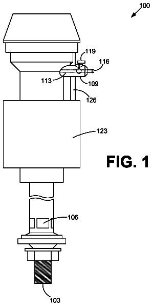
Various embodiments are directed towards toilet fill valves with adjustable bowl fill flow.
US 8,650,868 B2 · Assignee: Panasonic Corporation · Inventors: Komatsu; Mayumi et al.
Sheet 1 of 12 from the published document. All sheets in the USPTO PDF
There is provided an abnormality determination unit that determines whether or not an output measurement unit is abnormal, in order to determine abnormality of the output measurement unit. When the output measurement unit is abnormal, the operation of an elastic actuator is controlled not in accordance with a measurement result of the output measurement unit but in accordance with an internal state model.
In recent years, active development of robots cooperating with workers has been observed because of increase in cell production plants and the like. Unlike those conventional robots operating in areas separated from workers' areas, these robots cooperating with workers need to share the work areas with the workers. Accordingly, specifications required to these cooperative robots are different from the conventional industrial robots and the like. Firstly, a conventional industrial robot includes an electric motor or a decelerator, and achieves high accuracy in positioning a hand such as repeatability of about 0.1 mm by feedback control with high gain. However, a mechanism driven by such an electric motor is highly rigid with poor flexibility in many cases, which is problematic in terms of safety. To the contrary, safety is quite important to a robot cooperating with a worker so as not to
8 of 12 drawing sheets so far from the published document, cropped to the drawing. Every sheet is in the USPTO PDF.
What the patent claimed, word for word. All of it is now free to use.
The technical field relates to a control apparatus, a control method, and a control program for an elastic actuator drive mechanism, used for controlling operations of the drive mechanism that is driven by an elastic actuator such as a fluid pressure drive actuator, which is driven due to deformation of an elastic body.
In recent years, active development of robots cooperating with workers has been observed because of increase in cell production plants and the like. Unlike those conventional robots operating in areas separated from workers' areas, these robots cooperating with workers need to share the work areas with the workers. Accordingly, specifications required to these cooperative robots are different from the conventional industrial robots and the like.
Firstly, a conventional industrial robot includes an electric motor or a decelerator, and achieves high accuracy in positioning a hand such as repeatability of about 0.1 mm by feedback control with high gain. However, a mechanism driven by such an electric motor is highly rigid with poor flexibility in many cases, which is problematic in terms of safety.
To the contrary, safety is quite important to a robot cooperating with a worker so as not to hurt the worker by contact with each other. Therefore, such a mechanism driven by the electric motor as in the conventional industrial robot is unsuited to domestic robots and the like in the fields in which safety is highly required, and there is a need for flexible and safe robot arms.
In order to solve the problems, there has been proposed a robot arm that includes a pneumatic actuator of Mckibben type, for example. The pneumatic actuator of Mckibben type is configured such that a restraint part made of fiber cords is provided on an outer surface of a tubular elastic body made of a rubber material, and respective ends of the tubular elastic body are hermetically sealed by sealing members. When an internal pressure is applied to an inner space of the tubular elastic body with use of a compressive fluid such as air through a fluid injection/ejection part, the tubular elastic body tends to expand mainly in a radial direction. However, the restraint part functions to convert the radially expanding motion to a motion along a center axis of the tubular elastic body. As a result, the tubular elastic body is contracted in the entire length. This Mckibben type actuator is mainly configured by an elastic body, and is thus characterized by being flexible, safe, and light in weight.
Secondly, the conventional industrial robot operates in the area separated from the workers' area. Accordingly, safety is considered to be most preferably achieved by immediately stopping the robot in case of malfunction of a sensor or the like.
To the contrary, with a robot operating in the workers' area, it is not always safest to immediately stop the robot in case of malfunction of a sensor or the like. For example, even when the robot cooperating with a worker suddenly stops, the cooperative worker may be unable to immediately stop and thus may be in danger. However, when the sensor is in trouble, it is impossible to obtain information necessary for operation control. Therefore, it is difficult to operate the robot continuously.
In order to cope with such malfunction of a sensor, there has been disclosed, as a conventional technique, a control apparatus that controls a robot by reading data preliminarily instructed and stored, instead of a sensor signal (Patent Literature 1). There has been also disclosed a shift control apparatus for use in a robot including a distance sensor and a plurality of shift mechanism position detectors, the shift control apparatus including a computing unit that obtains an alternative signal same as a correct shift mechanism position signal to be originally transmitted from a broken shift mechanism position detector, from a sensor signal from the distance sensor and a shift mechanism position signal from the normal shift mechanism position detector (Patent Literature 2).
Patent Literature
Patent Literature 1: Japanese Examined Utility Model Publication No.
H08-1819
Patent Literature 2: Japanese Examined Patent Publication No.
H05-55279
The technique disclosed in Patent Literature 1 preliminarily requires the instructed data to be used in place of a sensor signal. However, it is difficult to estimate in advance every operations of a robot and is therefore hard to prepare such instructed data. Further, the technique disclosed in Patent Literature 2 has a problem that a correct alternative signal cannot be computed for a robot provided with no distance sensor.
One non-limiting and exemplary embodiment provides a control apparatus, a control method, and a control program for an elastic actuator drive mechanism, each of which achieves continuous operations of a drive mechanism of a robot arm or the like driven by an elastic actuator, without immediately stopping the robot arm even in cases of malfunction of a sensor, with no need for preliminary preparation of instructed data or provision of a sensor enabling computation of an alternative signal.
Additional benefits and advantages of the disclosed embodiments will be apparent from the specification and Figures. The benefits and/or advantages may be individually provided by the various embodiments and features of the specification and drawings disclosure, and need not all be provided in order to obtain one or more of the same.
In one general aspect, the techniques disclosed here feature: a control apparatus of an elastic actuator drive mechanism, comprising:
an abnormality determination unit that determines whether or not an output measurement unit that measures an output of an elastic actuator is abnormal;
a normal case operation control unit that controls the elastic actuator drive mechanism in accordance with an output of the output measurement unit when the abnormality determination unit determines that the output measurement unit is normal;
an abnormal case operation control unit that controls the elastic actuator drive mechanism in accordance with an internal state model when the abnormality determination unit determines that the output measurement unit is abnormal; and
a control unit that operates the normal case operation control unit when the abnormality determination unit determines that the output measurement unit is normal, and that switches from the normal case operation control unit to the abnormal case operation control unit so as to operate the abnormal case operation control unit when the abnormality determination unit determines that the output measurement unit is abnormal; wherein
the normal case operation control unit comprises:
a first desired output unit that outputs a desired value of the output of the elastic actuator; and
a torque control unit that calculates a desired joint torque in accordance with an output of the first desired output unit and the output of the output measurement unit,
the normal case operation control unit controls the elastic actuator drive mechanism in accordance with the desired joint torque calculated by the torque control unit,
the abnormal case operation control unit comprises:
a second desired output unit that outputs a desired value of the output of the elastic actuator; and
a desired internal state information acquisition unit that acquires desired internal state information on the elastic actuator in accordance with a desired value of the output of the second desired output unit and the internal state model, and
the abnormal case operation control unit controls the elastic actuator drive mechanism not in accordance with a measurement result of the output of the elastic actuator but in accordance with the desired internal state information acquired by the desired internal state information acquisition unit so that the elastic actuator is operated continuously.
These general and specific aspects may be implemented using a system, a method, and a computer program, and any combination of systems, methods, and computer programs.
A control apparatus of an elastic actuator drive mechanism according to the one general aspect includes the control unit, the normal case operation control unit, and the abnormal case operation control unit. Further, the normal case operation control unit is provided with the abnormality determination unit that determines whether or not an output measurement unit is in trouble. In this configuration, when the abnormality determination unit determines that the output measurement unit is not normal, the operation can be switched, by the control unit, from the normal case operation control unit to the abnormal case operation control unit. As a result, the abnormal case operation control unit controls the elastic actuator drive mechanism not in accordance with a measurement result of an output of the elastic actuator but in accordance with the internal state model, so that the elastic actuator is operated continuously. Therefore, even in a case where the output measurement unit is in trouble, the elastic actuator drive mechanism is controlled not to be stopped immediately but to be operable continuously and safely.
Further, a control method and a control program for an elastic actuator drive mechanism according to the another general aspect includes the abnormality determination operation of determining whether or not the output measurement unit is in trouble. In this configuration, when the abnormality determination unit determines that the output measurement unit is not normal, the operation can be switched, by the control unit, from the normal case operation control unit to the abnormal case operation control unit. As a result, the abnormal case operation control unit controls the elastic actuator drive mechanism not in accordance with a measurement result of an output of the elastic actuator but in accordance with the internal state model, so that the elastic actuator is operated continuously. Therefore, even in a case where the output measurement unit is in trouble, the elastic actuator drive mechanism is controlled not to be stopped immediately but to be operable continuously and safely.
These and other aspects and features of the present invention will become clear from the following description taken in conjunction with the embodiments thereof with reference to the accompanying drawings, in which:
FIG. 1 is a view showing a configuration of an elastic actuator drive mechanism according to a first embodiment of the present invention;
FIG. 2 is a view showing a configuration and operations of each of elastic expansion/contraction structures serving as examples of elastic actuators according to the first embodiment;
FIG. 3 is a view showing operations of a pneumatic pressure supply system according to the first embodiment of the present invention, for driving a robot arm by means of air serving as a compressive fluid;
FIG. 4 is a block diagram showing an entire configuration of a control apparatus of the elastic actuator drive mechanism according to the first embodiment of the present invention;
FIG. 5 is a block diagram showing a configuration of a main control unit according to the first embodiment of the present invention;
FIG. 6A is a graph indicating an example of an equation for an internal state model according to the first embodiment of the present invention;
FIG. 6B is a graph indicating another example of the equation for the internal state model according to the first embodiment of the present invention;
FIG. 7 is a flowchart showing operation steps of a control program for the main control unit according to the first embodiment of the present invention;
FIG. 8 is a control block diagram of a normal case operation control unit according to the first embodiment of the present invention;
FIG. 9 is a view partially indicating a calculation method of a torque control unit according to the first embodiment of the present invention;
FIG. 10 is a graph indicating an example of characteristics of the elastic actuators according to the first embodiment of the present invention;
FIG. 11 is a view showing internal blocks of an abnormality determination unit according to the first embodiment of the present invention;
FIG. 12 is a flowchart showing operation steps of a control program for the normal case operation control unit according to the first embodiment of the present invention;
FIG. 13 is a control block diagram of an abnormal case operation control unit according to the first embodiment of the present invention;
FIG. 14 is a block diagram showing a detailed configuration of a desired internal state determination unit according to the first embodiment of the present invention;
FIG. 15 is a flowchart showing operation steps of a control program for the abnormal case operation control unit according to the first embodiment of the present invention; and
FIG. 16 is a control block diagram of an abnormal case operation control unit according to a second embodiment of the present invention.
Described in detail below are embodiments of the present invention with reference to the accompanying drawings.
Before detailing the embodiments of the present invention with reference to the drawings, reference is made to various aspects of the present invention.
According to a first aspect of the present invention, there is provided a control apparatus of an elastic actuator drive mechanism, comprising:
an abnormality determination unit that determines whether or not an output measurement unit that measures an output of an elastic actuator is abnormal;
a normal case operation control unit that controls the elastic actuator drive mechanism in accordance with an output of the output measurement unit when the abnormality determination unit determines that the output measurement unit is normal;
an abnormal case operation control unit that controls the elastic actuator drive mechanism in accordance with an internal state model when the abnormality determination unit determines that the output measurement unit is abnormal; and
a control unit that operates the normal case operation control unit when the abnormality determination unit determines that the output measurement unit is normal, and that switches from the normal case operation control unit to the abnormal case operation control unit so as to operate the abnormal case operation control unit when the abnormality determination unit determines that the output measurement unit is abnormal; wherein
the normal case operation control unit comprises:
a first desired output unit that outputs a desired value of the output of the elastic actuator; and
a torque control unit that calculates a desired joint torque in accordance with an output of the first desired output unit and the output of the output measurement unit,
the normal case operation control unit controls the elastic actuator drive mechanism in accordance with the desired joint torque calculated by the torque control unit,
the abnormal case operation control unit comprises:
a second desired output unit that outputs a desired value of the output of the elastic actuator; and
a desired internal state information acquisition unit that acquires desired internal state information on the elastic actuator in accordance with a desired value of the output of the second desired output unit and the internal state model, and
the abnormal case operation control unit controls the elastic actuator drive mechanism not in accordance with a measurement result of the output of the elastic actuator but in accordance with the desired internal state information acquired by the desired internal state information acquisition unit so that the elastic actuator is operated continuously.
According to a second aspect of the present invention, there is provided the control apparatus according to the first aspect, wherein the desired internal state information acquisition unit of the abnormal case operation control unit comprises a first desired internal state calculation unit that calculates desired internal state information in accordance with the desired value of the output of the second desired output unit and the internal state model, and the elastic actuator drive mechanism is controlled in accordance with the desired internal state information calculated by the first desired internal state calculation unit so that the elastic actuator is operated continuously.
According to a third aspect of the present invention, there is provided the control apparatus according to the first aspect, wherein the desired internal state information acquisition unit of the abnormal case operation control unit comprises:
an output estimation unit that estimates the output of the elastic actuator in accordance with the internal state model and the internal state information on the elastic actuator; and
a second desired internal state information calculation unit that calculates desired internal state information in accordance with the output of the elastic actuator estimated by the output estimation unit and the desired value of the output of the second desired output unit; and
the elastic actuator drive mechanism is controlled in accordance with the desired internal state information calculated in accordance with the output of the elastic actuator estimated by the output estimation unit, so that the elastic actuator is operated continuously.
According to a fourth aspect of the present invention, there is provided the control apparatus according to the first aspect, wherein the abnormality determination unit compares information on a relationship between the output of the output measurement unit and an internal state from an internal state measurement unit that measures an internal state of the elastic actuator, with information on a relationship between the output of the elastic actuator and the internal state of the elastic actuator in an internal state model for the output measurement unit being normal, to determine whether or not the output measurement unit is abnormal.
According to a fifth aspect of the present invention, there is provided the control apparatus of an elastic actuator drive mechanism according to any one of the first to fourth aspects, wherein the second desired output unit in the abnormal case operation control unit and the first desired output unit in the normal case operation control unit output desired values of different outputs of the elastic actuator, respectively, to control by the abnormal case operation control unit, when the abnormal case operation control unit is operated, such that the elastic actuator moves to a safety position and then stops.
According to a sixth aspect of the present invention, there is provided the control apparatus of an elastic actuator drive mechanism according to any one of the first to fourth aspects, wherein the elastic actuator is a fluid pressure actuator.
According to a seventh aspect of the present invention, there is provided a method of controlling an elastic actuator drive mechanism, the method comprising:
determining, by an abnormality determination unit, whether or not an output measurement unit that measures an output of an elastic actuator is abnormal;
controlling, by a normal case operation control unit, the elastic actuator drive mechanism in accordance with an output of the output measurement unit, when the abnormality determination unit determines that the output measurement unit is normal, or
controlling, by an abnormal case operation control unit, the elastic actuator drive mechanism in accordance with an internal state model, when the abnormality determination unit determines that the output measurement unit is abnormal;
operating, by a control unit, the normal case operation control unit when the abnormality determination unit determines that the output measurement unit is normal, or switching from the normal case operation control unit to the abnormal case operation control unit to operate the abnormal case operation control unit by the control unit, when the abnormality determination unit determines that the output measurement unit is abnormal;
when the normal case operation control unit is operated,
outputting, from a first desired output unit, a desired value of the output of the elastic actuator, and
calculating, by a torque control unit, a desired joint torque in accordance with an output of the first desired output unit and the output of the output measurement unit, to control the elastic actuator drive mechanism in accordance with the desired joint torque calculated by the torque control unit; and
when the abnormal case operation control unit is operated,
outputting, from a second desired output unit, a desired value of the output of the elastic actuator, and
acquiring, by a desired internal state information acquisition unit, desired internal state information on the elastic actuator in accordance with the desired value of the output of the second desired output unit and the internal state model, to control the elastic actuator drive mechanism not in accordance with a measurement result of the output of the elastic actuator but in accordance with the desired internal state information acquired by the desired internal state information acquisition unit so that the elastic actuator is operated continuously.
According to an eighth aspect of the present invention, there is provided a control program for an elastic actuator drive mechanism, the program causing a computer to execute functions of:
determining, by an abnormality determination unit, whether or not an output measurement unit that measures an output of an elastic actuator is abnormal;
controlling, by a normal case operation control unit, the elastic actuator drive mechanism in accordance with an output of the output measurement unit, when the abnormality determination unit determines that the output measurement unit is normal;
controlling, by an abnormal case operation control unit, the elastic actuator drive mechanism in accordance with an internal state model, when the abnormality determination unit determines that the output measurement unit is abnormal;
operating, by a control unit, the normal case operation control unit when the abnormality determination unit determines that the output measurement unit is normal, or switching from the normal case operation control unit to the abnormal case operation control unit to operate the abnormal case operation control unit by the control unit, when the abnormality determination unit determines that the output measurement unit is abnormal;
when the normal case operation control unit is operated,
outputting, from a first desired output unit, a desired value of the output of the elastic actuator, and
calculating, by a torque control unit, a desired joint torque in accordance with an output of the first desired output unit and the output of the output measurement unit, to control the elastic actuator drive mechanism in accordance with the desired joint torque calculated by the torque control unit; and
when the abnormal case operation control unit is operated,
outputting, from a second desired output unit, a desired value of the output of the elastic actuator, and
acquiring, by a desired internal state information acquisition unit, desired internal state information on the elastic actuator in accordance with the desired value of the output of the second desired output unit and the internal state model, to control the elastic actuator drive mechanism not in accordance with a measurement result of the output of the elastic actuator but in accordance with the desired internal state information acquired by the desired internal state information acquisition unit so that the elastic actuator is operated continuously.
Described below are the embodiments of the present invention with reference to the accompanying drawings.
(First Embodiment)
Description is made to an example of a specific configuration of a control apparatus 30 of an elastic actuator drive mechanism 10 according to the first embodiment.
FIG. 1 is a view showing a configuration of the elastic actuator drive mechanism 10 according to the first embodiment of the present invention. The elastic actuator drive mechanism 10 is configured as a robot arm of two degrees of freedom, including a first joint shaft 6-1 and a second joint shaft 6-2. The first joint shaft 6-1 rotates positively and negatively within an xy plane inclusive of an x axis and a y axis provided perpendicularly to each other. The second joint shaft 6-2 also rotates positively and negatively within the xy plane. FIG. 1 illustrates elastic expansion/contraction structures 1-1a, 1-1b, 1-2a, and 1-2b, which are provided separately from one another as examples of elastic actuators or fluid pressure actuators. The elastic expansion/contraction structures will be denoted by reference sign 1 if indicated representatively. The first joint shaft 6-1 and the second joint shaft 6-2 serve as rotary shafts of a first joint and a second joint, respectively, of the elastic actuator drive mechanism (an elastic expansion/contraction structure drive mechanism in the present embodiment) 10.
As shown in FIG. 2, each of the elastic expansion/contraction structures 1 includes a hollow tubular elastic body 2 and a deformation direction regulation member 3. The tubular elastic body 2 is made of a rubber material and serves as a driving unit. The deformation direction regulation member 3 is made of resin or metal fiber cords, which are less likely to stretch and is woven into a mesh shape. The deformation direction regulation member 3 is provided on an outer surface of the tubular elastic body 2. The deformation direction regulation member 3 is configured such that deformation in the radial direction due to expansion of the tubular elastic body 2 is converted to contraction in length in the axial direction perpendicular to the radial direction, while deformation in the radial direction due to contraction of the tubular elastic body 2 is converted to expansion in length in the axial direction. The tubular elastic body 2 has two ends that are hermetically sealed by sealing members 4, respectively. The sealing member 4 at one of the ends of the elastic expansion/contraction structure 1 is provided with a tubular fluid passage member 5. The fluid passage member 5 is provided therein with a flow passage through which a compressive fluid passes, so that the fluid can be injected into and ejected from the hollow inner space of the hollow tubular elastic body 2 through the fluid passage member 5. The compressive fluid such as air is supplied into the hollow tubular elastic body 2 by way of the fluid passage member 5. Alternatively, the fluid passage member 5 may be provided at each of the sealing members 4 at the respective ends of the elastic expansion/contraction structure 1.
When an internal pressure is applied to the inner space of the tubular elastic body 2 by the compressive fluid thus supplied, the tubular elastic body 2 tends to expand mainly in the radial direction. However, the deformation direction regulation member 3 functions to convert the expansion in the radial direction to the motion along the center axis of the tubular elastic body 2, and thus the tubular elastic body 2 is contracted in the entire length. In this manner, the elastic expansion/contraction structure can be applicable as an elastic actuator that is driven linearly.
Referring again to FIG. 1, the elastic actuator drive mechanism 10 includes the pair of elastic expansion/contraction structures 1 that are provided to face each other and are supported at the joint shaft 6-1 or 6-2 serving as a support point. One of the paired elastic expansion/contraction structures 1 is contracted, while another one of which is expanded. A force is applied by way of the support point (the joint shaft 6-1 or 6-2) so that the joint shaft 6-1 or 6-2 is axially rotated to be driven antagonistically. Accordingly, positive rotation and negative rotation can be enabled at the joint shaft 6-1 or 6-2. More specifically, the elastic expansion/contraction structures 1-1a and 1-1b are driven antagonistically to rotate the first joint shaft 6-1 positively and negatively. Further, the elastic expansion/contraction structures 1-2a and 1-2b are driven antagonistically to rotate the second joint shaft 6-2 positively and negatively.
There is provided a support member 16 in a bar shape. The support member 16 has a lower end fixed to a fixing surface 14, and an upper end to which a support body 19 in a circular disc shape, for example, is supported to be rotatable coaxially with the first joint shaft 6-1. There is further provided a support body 18 that is fixed to the lower end fixed to the fixing surface 14, of the support member 16. The support body 18 has a bar shape and extends perpendicularly to the longitudinal direction of the support member 16. The ends of the elastic expansion/contraction structures 1-1a and 1-1b are rotatably coupled to the support body 19 and the support body 18, respectively. When the elastic expansion/contraction structures 1-1a and 1-1b are driven antagonistically, the support body 19 is rotated positively and negatively about a support shaft 21 of the first joint shaft 6-1 within the xy plane. As a result, in the elastic actuator drive mechanism 10, a front arm support member 17, which is coupled to the support body 19 (illustrated as a quadrilateral plate member in FIG. 3), can be rotated positively and negatively.
The support member 17 for a front arm 117 has a proximal end fixed to the support body 19 (illustrated in FIG. 3), so as to be rotatable integrally with the support body 19.
The support member 17 has a distal end coupled with a center of a support body 20, which has a bar shape and is fixed so as to extend perpendicularly to the longitudinal direction of the support member 17, so that the support body 20 is rotatable about the axis of the second joint shaft 6-2. Between the support body 19 connected with one of the ends of the support member 17 and the support body 20 coupled with the distal end of the support member 17, the elastic expansion/contraction structures 1-2a and 1-2b are provided and the ends thereof are rotatably coupled to the support bodies, respectively. The elastic expansion/contraction structures 1-2a and 1-2b are driven antagonistically to rotate the support body 20 positively and negatively within the xy plane about a support shaft 22 of the second joint shaft 6-2. As a result, a hand 12 for gripping an object, which is coupled to the support body 20, can be relatively rotated positively and negatively.
A motor 13 for opening/closing the hand 12 is attached to the hand 12. When the motor 13 is operated, the hand 12 is closed to grip an object 11 to be conveyed. The position and the posture of the hand 12 are described as the position and the posture of an arm tip (hand).
Pressure sensors 9-1a and 9-1b are provided as examples of internal state measurement units that measure the internal states (internal pressures as one example thereof) of the elastic expansion/contraction structures 1-1a and 1-1b, respectively. The pressure sensors 9-1a and 9-1b are provided to the fluid passage members 5 (fluid injection/ejection ports) of the elastic expansion/contraction structures 1-1a and 1-1b, and measure the pressures in the elastic expansion/contraction structures 1-1a and 1-1b, respectively. Similarly, the elastic expansion/contraction structures 1-2a and 1-2b are provided with pressure sensors 9-2a and 9-2b as examples of internal state measurement units, respectively.
As to be described later, there are provided three-port flow rate proportional solenoid valves 27 (27A and 27B), which are connected to the elastic expansion/contraction structures 1-1a and 1-1b and the elastic expansion/contraction structures 1-2a and 1-2b, respectively. All the flow rate proportional solenoid valves 27 are connected to a control computer 28 that is configured by an ordinary personal computer and an input/output IF 29. The control computer 28 independently controls contracting and expanding motions of the elastic expansion/contraction structures 1-1a and 1-1b and the elastic expansion/contraction structures 1-2a and 1-2b, through the flow rate proportional solenoid valves 27. The joint shafts 6-1 and 6-2 are provided respectively with displacement measurement units (encoders 8 provided as one example thereof in the first embodiment) as output measurement units, for example. The encoders 8 can measure joint angles of the joint shafts 6-1 and 6-2, respectively. The elastic expansion/contraction structures 1 are provided with pressure measurement units (the pressure sensors 9 (9-1a, 9-1b, 9-2a, and 9-2b) provided as examples thereof in the first embodiment) as one example of the internal state measurement units so that the pressure sensors 9 can measure the internal pressures of the elastic expansion/contraction structures 1, respectively.
The above configuration can realize basic functions of the elastic actuator drive mechanism 10, such as gripping and conveying an object, due to multiple degrees of freedom.
FIG. 3 is a view showing a configuration of a pneumatic pressure supply system for driving the elastic actuator drive mechanism 10 according to the first embodiment of the present invention.
FIG. 3 illustrates only a relevant portion for driving to rotate positively and negatively the second joint shaft 6-2 in the elastic actuator drive mechanism 10, while the remaining portion does not appear in the figure. It is noted that a relevant portion for driving to rotate positively and negatively the first joint shaft 6-1 in the elastic actuator drive mechanism 10 is configured and operated similarly.
FIG. 3 illustrates a pneumatic pressure source 25 such as a compressor, and a pneumatic pressure adjustment unit 26 for adjusting the pneumatic pressure of the pneumatic pressure source 25 to output the pneumatic pressure thus adjusted. Each of four three-port flow rate control solenoid valves 27 provided as one example of the flow rate proportional solenoid valve controls the flow rate by driving a spool valve or the like with use of a force of an electromagnet. The control computer 28 is mounted with the input/output IF 29 such as a D/A board, and outputs a voltage command value to each of the four three-port flow rate control solenoid valves 27 so as to independently control the flow rate of air flowing through each of the fluid passage members 5.
Described next are operations of the pneumatic pressure supply system shown in FIG. 3. Highly pressurized air generated by the pneumatic pressure source 25 is reduced in pressure by the pneumatic pressure adjustment unit 26, e.g. adjusted to a constant pressure such as 600 [kPa]. The air thus obtained is supplied to the three-port flow rate control solenoid valves 27. The opening degree of each of the three-port flow rate control solenoid valves 27 is controlled in proportion to the voltage command value transmitted from the control computer 28 by way of the input/output IF 29. When a positive voltage command value is transmitted from the control computer 28 to the three-port flow rate control solenoid valve 27A that is connected to the elastic expansion/contraction structure 1-2a, the flow passage from the pneumatic pressure source 25 to the elastic expansion/contraction structure 1-2a is opened, and air of a flow rate in proportion to the absolute value of the voltage command value is supplied to the elastic expansion/contraction structure 1-2a. If a negative voltage command value is simultaneously transmitted to the three-port flow rate control solenoid valve 27B that is connected to the elastic expansion/contraction structure 1-2b, the flow passage from the elastic expansion/contraction structure 1-2b toward the atmospheric pressure is opened, and air of a flow rate in proportion to the absolute value of the voltage command value is discharged from the elastic expansion/contraction structure 1-2b into the atmosphere.
Therefore, as shown in FIG. 2, the elastic expansion/contraction structure 1-2a (corresponding to the lower elastic expansion/contraction structure in FIG. 2) is contracted in the entire length, and the elastic expansion/contraction structure 1-2b (corresponding to the upper elastic expansion/contraction structure in FIG. 2) is expanded in the entire length, so that the second joint shaft 6-2 is rotated to the right at a velocity in proportion to the absolute value of the voltage command value. On the other hand, when a negative voltage command value is transmitted from the control computer 28 to the three-port flow rate control solenoid valve 27A that is connected to the elastic expansion/contraction structure 1-2a and a positive voltage command value is transmitted therefrom to the three-port flow rate control solenoid valve 27B that is connected to the elastic expansion/contraction structure 1-2b, the elastic expansion/contraction structures 1-2a and 1-2b are operated reversely (specifically, the elastic expansion/contraction structure 1-2a is expanded in the entire length and the elastic expansion/contraction structure 1-2b is contracted in the entire length), so that the second joint shaft 6-2 is rotated to the left.
In this case, the flow of air supplied from the three-port flow rate control solenoid valve 27 to the elastic expansion/contraction structure 1 passes through the sealing member 4 due to the provision of the fluid passage member 5, and enters the tubular elastic body 2 to generate an internal pressure of the tubular elastic body 2. Each of the tubular elastic bodies 2 is expanded by the internal pressure thus generated. Radial deformation due to such expansion is restricted due to the restraint (regulation) of the fiber cords woven into the mesh shape of the deformation direction regulation member 3 and is converted to contraction in the axial length. Accordingly, the elastic expansion/contraction structure 1 is decreased in the entire length as illustrated as the upper elastic expansion/contraction structure in FIG. 3 (the lower elastic expansion/contraction structure in FIG. 2). On the other hand, when air is discharged from the three-port flow rate control solenoid valve 27 into the atmosphere to reduce the internal pressure of the tubular elastic body 2, expansion of the tubular elastic body 2 is cancelled by the elastic force thereof and the tubular elastic body 2 is restored. Accordingly, the elastic expansion/contraction structure 1 is expanded in the entire length as shown as the lower elastic expansion/contraction structure in FIG. 3 (the upper elastic expansion/contraction structure in FIG. 2).
As a result, assuming that each of the tubular elastic bodies is fixed at the right end in FIG. 2, such expansion and contraction cause a difference of a distance d at the left ends of the tubular elastic bodies 2. Therefore, the elastic expansion/contraction structures 1 according to the first embodiment are capable of functioning as linearly displaced actuators due to the control on supply of pneumatic pressures. The amounts of expansion and contraction are generally in proportion to the internal pressures of the elastic expansion/contraction structures 1. Therefore, the elastic expansion/contraction structures 1 can be each controlled in the entire length when the control computer 28 controls the three-port flow rate control solenoid valves 27 to control the flow rate of air supplied into the elastic expansion/contraction structures 1.
The description continues in the full USPTO document.
About 6,270 words. The USPTO PDF has it with every drawing.
Fees are due 3.5, 7.5 and 11.5 years after grant. This patent expired on February 18, 2026, so the fee marked "not paid" was the one that went unpaid.
CONTROL APPARATUS, CONTROL METHOD, AND CONTROL PROGRAM FOR ELASTIC ACTUATOR DRIVE MECHANISM
Filed Sep 2012 · published Jan 2013Control apparatus, control method, and control program for elastic actuator drive mechanism
Filed Sep 2012 · granted Feb 2014Earlier publications, parents and continuations. None of them can still be enforced, or this patent would not be listed.
Prior art cited by the examiner or applicant. Useful when you check your own idea for novelty.
Everything on this page comes from the documents linked above.


