 Lapsed, fee not paid14 drawings
Firearms & Defense · US 8,650,000 B2
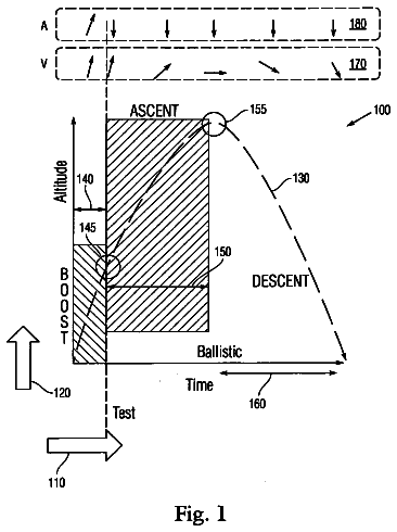
Ballistic missile phase categorization technique
A computer-implemented analysis method is provided for identifying a flight trajectory of a bogey relative to earth's surface.
US 8,650,794 B2 · Assignee: S&S Precision, LLC · Inventors: Swan; Johnny E. et al.
Sheet 1 of 10 from the published document. All sheets in the USPTO PDF
Claude doesn't help design weapons, ammunition or explosives, so this page has no Reinvent kit. To develop this one, work with a federally licensed manufacturer (many of these items are regulated) and a registered patent attorney or agent, listed on the USPTO roster.
Embodiments include a method and apparatus for removably connecting a firearm, accessory, or tool to a surface, material, object, belt, vehicle, pocket, or tactical equipment. The apparatus may include a first connecting member operatively connectible to the firearm, accessory, or tool and a second connecting member operatively connectible to the surface, material, object, belt, vehicle, pocket, or tactical equipment. The first connecting member and second connecting member are capable of connection to one another to connect the firearm, accessory, or tool to the surface, material, object, belt, vehicle, pocket, or tactical equipment.
During military and law enforcement operations, individuals must routinely conduct activities without anything in their hands (hands-free activity). These potentially dangerous operations would typically require the individual (e.g., a soldier or police officer) to carry a firearm such as a rifle-type firearm for personal protection, which most likely would require a sling system in order to retain the rifle on the individual. Modern-day slings come in a variety of shapes and sizes. For this discussion, we will focus on a single point sling 990, such as is shown in FIG. 21. A single point sling 990 is a simple continuous loop of flat fiber strapping or webbing material made of nylon or cotton with a single metal fastener that connects to a rifle 4 at a single point 995, hence its being referred to as a "single" point sling 990. This single point sling 990 is typically worn over the upper
8 of 10 drawing sheets so far from the published document, cropped to the drawing. Every sheet is in the USPTO PDF.
What the patent claimed, word for word. All of it is now free to use.
Embodiments generally relate to the attachment of accessories to military and law enforcement tactical equipment, belts, vehicles, or other objects, surfaces, or materials. More particularly, some embodiments relate to the attachment or optional mounting of firearms or assault rifles onto tactical equipment, belts, vehicles, or other objects.
During military and law enforcement operations, individuals must routinely conduct activities without anything in their hands (hands-free activity). These potentially dangerous operations would typically require the individual (e.g., a soldier or police officer) to carry a firearm such as a rifle-type firearm for personal protection, which most likely would require a sling system in order to retain the rifle on the individual.
Modern-day slings come in a variety of shapes and sizes. For this discussion, we will focus on a single point sling 990, such as is shown in FIG. 21. A single point sling 990 is a simple continuous loop of flat fiber strapping or webbing material made of nylon or cotton with a single metal fastener that connects to a rifle 4 at a single point 995, hence its being referred to as a "single" point sling 990. This single point sling 990 is typically worn over the upper torso of an individual's body 996 in order to retain the rifle 4 thereon. While the rifle 4 may be connected to the upper torso, it is far from being securely held onto the body 996; rather, the rifle 4 may loosely spin, twist or fly around during vigorous activities such as climbing, fast roping, or detaining a suspect. Not only is the loose rifle a hazard to the individual but also to the individual's team members, equipment and suspects during detaining.
Therefore, there is a need to correct this potential hazard with a higher level of weapon retention via a weapon retention device. A weapon retention device is also needed which is lightweight and is a low profile projection from the rifle or other firearm.
Thus, the current popular method for attachment of an assault rifle 4 onto tactical equipment is the use of nylon webbing as a sling (e.g., sling 990 shown in FIG. 21). The sling 990 is configured in such a manner that it creates a loop of webbing from the rifle 4 at one point, such as the point shown in FIG. 21 referred to as the around the individual 996 and back to the rifle 4 at the same point or other point depending on individual preference.
As the sling is a simple loop of material around the individual, it provides no real retention of the rifle during other activities that require the rifle to be out of the way and secure. When the weight of the rifle is solely loaded on the sling without the individual touching the rifle, the rifle is referred to as "slung". When the rifle is slung to the front position, side position, or the back of the body, it is not held in position by anything other than gravity tension on the sling and the lack of movement by the individual. If the individual were to climb, walk, run, bend over, or fall down, the rifle would move out of its intended position. Therefore, there exists a need to facilitate a convenient and secure attachment and detachment method of the rifle or other firearm and/or one or more accessories to tactical equipment, belts, vehicles, or other objects.
To this end, embodiments advantageously include a device or apparatus which provides for secure, convenient, fast, and easy attachment and/or detachment of a firearm, tool, and/or accessory to/from tactical equipment, objects, surfaces, or materials.
Embodiments may further include the option of one-handed attachment and/or detachment of the firearm, tool, and/or accessory to/from tactical equipment, objects, surfaces, or materials.
Embodiments may advantageously provide attachment a weapon retention device or firearm fastener with positional security.
Embodiments may provide a weapon retention device which is lightweight and is a low profile projection from the rifle or other firearm.
Embodiments generally include an apparatus for connecting a firearm to tactical equipment or a material or object, comprising a first connecting member operatively and fixedly attachable to the firearm; a second connecting member operatively and fixedly attachable to the tactical equipment or material or object, wherein the first connecting member and second connecting member are removably attachable to one another to connect the firearm to the tactical equipment or material or object. Embodiments may also include an apparatus for connecting a firearm to tactical equipment, a surface, or an object, comprising a clasping portion capable of fixing the apparatus horizontally to the firearm or a rail section attachable to the firearm or another object; a connector capable of fixing the apparatus vertically to the firearm or a rail section attachable to the firearm or another object; and a clipping portion capable of clipping the tactical equipment, surface, or object to the firearm, rail section, or other object.
Other embodiments may include a method of connecting a firearm to tactical equipment, comprising providing an apparatus having a first connecting member and a second connecting member; operatively connecting the first connecting member to a firearm or accessory, wherein the first connecting member is fixed in position along a length and width of the firearm or accessory; operatively connecting the second connecting member to tactical equipment or a surface or material, wherein the second connecting member is fixed in position along a length and width of the firearm or accessory; and connecting the first connecting member and second connecting member to one another, wherein the first connecting member and second connecting member are attachable and detachable from one another using one hand, wherein the first connecting member is operatively connected to the firearm or accessory using a clasping member to fix a width of the first connecting member and at least one first fastening member to fix a length of the first connecting member relative to the firearm or accessory; the second connecting member is operatively connected to the tactical equipment or surface or material using at least one second fastening member; and the first and second connecting member are connected to one another when a protruding mechanism in one of the connecting members cooperates with a slot in the other connecting member.
Some embodiments generally include an apparatus for connecting a firearm to tactical equipment, comprising a grabbing portion capable of positionally fixing the apparatus with respect to a width of the firearm or a rail section attachable to the firearm or another object; a connector capable of positionally fixing the apparatus with respect to a length of the firearm or a rail section attachable to the firearm or another object; and a clipping portion capable of clipping the tactical equipment to the firearm, rail section, or other object.
Other embodiments generally include a method of connecting a firearm or accessory to tactical equipment or a receiving piece operatively connected to a user's body, comprising providing an apparatus having a first connecting member and a second connecting member, the second connecting member including a hooking member; operatively connecting the first and second connecting member to one another and to the firearm or accessory so that the first and second connecting member cooperate to fix the apparatus in position along a length and width of the firearm or accessory; and hooking the tactical equipment or receiving piece to the apparatus by inserting the tactical equipment or receiving piece within the hooking member.
Yet other embodiments generally include an apparatus for connecting a firearm to tactical equipment, comprising a rail grabber having a hooking member for receiving and tensioning a strapping member, the hooking member having an opening which is wide enough to receive a thickness of the strapping member and narrow enough to maintain surface tension along the strapping member surface, the rail grabber for grabbing a rail connectable to a firearm and positionally maintaining the apparatus with respect to the rail.
So that the manner in which the above-recited features of embodiments can be understood in detail, a more particular description of the invention, briefly summarized above, may be had by reference to embodiments, some of which are illustrated in the appended drawings. It is to be noted, however, that the appended drawings illustrate only typical embodiments of this invention and are therefore not to be considered limiting of its scope, for the invention may admit to other equally effective embodiments.
FIG. 1 is a side perspective view of a first embodiment of a WeaponLink.TM. apparatus operatively attached to a rail system.
FIG. 2 is a side perspective view of a second embodiment of a WeaponLink.TM. apparatus operatively attached to a rail system.
FIG. 3 is a side perspective view of a third embodiment of a WeaponLink.TM. apparatus operatively attached to a rail system.
FIG. 4 is a bottom perspective view of the WeaponLink.TM. apparatus of FIG. 3.
FIG. 5 is an exploded view of the WeaponLink.TM. apparatus of FIG. 3.
FIG. 6 is an assembled side view of the WeaponLink.TM. apparatus of FIG. 3.
FIG. 7A is a perspective view of a male member of a fourth embodiment of a WeaponLink.TM. apparatus.
FIG. 7B is a perspective view of a female member of a fourth embodiment of a WeaponLink.TM. apparatus.
FIG. 8 is a perspective view of a female member of a fifth embodiment of a WeaponLink.TM. apparatus.
FIG. 9 is a side view of the female member of FIG. 7B.
FIG. 10 is a downward view of the female member of the WeaponLink.TM. apparatus of FIG. 3.
FIG. 11 is a view of a WeaponLink.TM. apparatus on a MOLLE system component.
FIG. 12 is a view of a WeaponLink.TM. apparatus on a portion of a belt.
FIG. 13 is a perspective view of a sixth embodiment of a WeaponLink.TM. apparatus operatively connected to a rail section.
FIG. 14 is a perspective view of a seventh embodiment of a WeaponLink.TM. apparatus operatively connected to a rail section.
FIG. 15 is a perspective view of an eighth embodiment of a WeaponLink.TM. apparatus.
FIG. 16 is a perspective view of the WeaponLink.TM. apparatus of FIG. 15 operatively connected to a rail section.
FIG. 17 is an exploded view of the WeaponLink.TM. apparatus of FIG. 15.
FIG. 18 is a perspective view of the WeaponLink.TM. apparatus of FIG. 15 operatively connected to a rail.
FIG. 19 is an exploded view of the WeaponLink.TM. apparatus of FIG. 15 detached from the rail of FIG. 18.
FIG. 20 is a view of the WeaponLink.TM. apparatus used with a sling system for a firearm.
FIG. 21 is a front view of a user having a single-point sling system disposed on his or her body.
FIG. 22 is a side view of the WeaponLink.TM. apparatus of embodiments cooperating with the single point sling system for secure weapon retention.
FIG. 23 is a front view of a user's body having the WeaponLink.TM. apparatus of embodiments cooperating with the single point sling system to hang a firearm from the front of a user's body for secure weapon retention.
FIG. 24 is a front view of the user's body having the WeaponLink.TM. apparatus of embodiments cooperating with the single point sling system to hang a firearm from the side of the body.
FIG. 25 is a side view of the back of the user's body having the WeaponLink.TM. apparatus of embodiments cooperating with the single point sling system to hang a firearm from the back of the body.
Embodiments may include a platform herein referred to as a WeaponLink.TM. apparatus, for example as shown and described in FIGS. 1-20 and 22-25, which is capable of accepting one or more multiple optional accessories (i.e. one or more firearms, assault rifles, mechanical tools, quick detach pouches, etc.) from one surface of tactical equipment to another surface or piece of equipment at desired locations and with positional security. The WeaponLink.TM. apparatus may include slides, threaded holes, spindles, clips, spring loaded tension devices, and/or other mounting fixtures suitable for securing the one or more accessories to various surfaces or tactical equipment. The WeaponLink.TM. apparatus may be configured to present a relatively low-profile protrusion from tactical equipment using physical surfaces that offer low risk of snagging or becoming caught in external devices when accessories are not in place. Embodiments may allow for adjustment of the position of the accessories when they are attached to the WeaponLink.TM. apparatus, which desirably may accept more than one optional accessory. Advantageously, the WeaponLink.TM. apparatus permits the user to attach and/or detach the accessories to and/or from the tactical equipment surface or other surface using only one hand with positional security resulting upon attachment. Embodiments advantageously allow addition of the WeaponLink.TM. apparatus to already-manufactured rail systems, tactical equipment, and optional accessories.
Generally, the WeaponLink.TM. apparatus may employ one or more mechanisms that may grab and tension one or more surfaces of tactical equipment, e.g., the side and top surfaces of a standard M1913A rail system or any other rail or rail system known to those skilled in the art. In some embodiments, the WeaponLink.TM. apparatus accessory mount may be secured to the rail system using one or more existing through-holes with one or more threaded fasteners, rivets, nuts, bolts, and/or spring loaded balls or plunger type devices which may be made, for example, from plastic (for light duty applications), stainless steel, aluminum, and/or forge-hardened steel.
A benefit of embodiments is that the WeaponLink.TM. apparatus mount may be added to already-manufactured rail systems, tactical equipment, and/or optional accessories. If necessary, the female and male interface shape of the WeaponLink.TM. apparatus (which may, for example, be round), may be modified to a dovetail, square, or other shape to accommodate generally positive fixture stability depending on shape design and customer requirements.
The WeaponLink.TM. apparatus acts as a fastener of a firearm, tool, or other accessory to a user's belt, vehicle, tactical gear, or other object, material, or surface. In one embodiment, a first portion of the WeaponLink.TM. apparatus is attachable to the firearm, tool, or other accessory, and a second portion of the WeaponLink.TM. apparatus is attachable to the user's belt, vehicle, tactical gear, or other object, material, or surface. The first and second portions may be attachable to one another and removable from one another, e.g., by moving a protrusion through a slot or by screwing or unscrewing motion, and may be lockable into place with respect to one another when moved or screwed in relationship to one another. One of the portions of the firearm fastener WeaponLink.TM. apparatus may include a hole through which the other corresponding portion of the firearm fastener is moveable or screwable into the locked or unlocked position.
The WeaponLink.TM. apparatus may be used to provide firearm/weapon retention during hands-free operations, for example during military or law enforcement use.
In some embodiments, the WeaponLink.TM. apparatus (in some embodiments a SlingClip.TM.) creates a secondary attachment point, which may be a temporary attachment point, for the single point sling to tighten the single point sling to the user's body. In this embodiment, the WeaponLink.TM. apparatus acts as a fulcrum or additional bend point in the flat woven strapping. By moving the WeaponLink.TM. apparatus further away from the sling's own single point attachment fastener, the sling becomes tighter against the user's upper torso. When the user routes the sling webbing material into the WeaponLink.TM. apparatus, it creates more tension and draws the rifle into a snug fit in the user's upper torso, thereby creating a much greater level of weapon/firearm retention.
Embodiments may also include using hooking action of the WeaponLink.TM. apparatus (in some embodiments a SlingClip.TM.) to hang or hook a firearm onto a receiving piece which may be a temporary receiving piece (e.g., belt, pants pocket, tactical vest of the user). The weight of the firearm may be used as a downward force on the hook of the SlingClip.TM. and receiving material and provide a quick and temporary firearm retention method.
The WeaponLink.TM. apparatus may be used as a low profile device on a rail system, e.g., on the M1913 Picatinny Rail System. The WeaponLink.TM. apparatus or SlingClip.TM. may be easily added to existing or already-manufactured rail systems and tactical equipment.
A first embodiment of the WeaponLink.TM. apparatus 10 is shown in FIG. 1. In this embodiment, the WeaponLink.TM. apparatus 10 may be a clip device. Depicted in FIG. 1 is a rail section 5 to which the apparatus 10 may be attachable. The rail section 5 may have ridges or raised portions 6 with spaced slots or cutouts 7 therebetween. In one embodiment, the rail section 5 is a M1913A Picatinny rail section, although the rail section 5 may instead be any type of rail section known to those skilled in the art. The rail section 5 may be attached to a firearm such as an assault rifle. The rail section 5 or rail may be a bracket connectable to a firearm for providing a standardized platform for mounting accessories thereto.
The apparatus 10 may include a connecting portion 20 which may be shaped to removably connect to the rail section 5, for example generally U-shaped. The generally U-shaped portion 20 of the apparatus 10 may include inward protrusions 16 on each bottom side (which is the top of the "U") which secure the apparatus 10 around the rail section 5. The distance between inner surfaces of the inward protrusions 16 may be less than the distance between inner surfaces of a portion of the U-shaped portion 20 to allow clasping of the apparatus 10 onto the rail section 5 while at the same time permitting movement of the apparatus 10 along the length L of the rail section 5.
One or more holes 17 through the portion 20 may accommodate one or more fastening members 25, e.g., one or more screws, bolts, and/or nuts. The one or more fastening members 25 may positionally secure the apparatus 10 to the rail section 5 at a location along the length L of the rail section 5. For example, screwing or inserting the fastening member(s) 25 into the hole(s) 17 may lock the apparatus 10 to the rail section 5 at a position along the length L of the rail section 5 and unscrewing or removing the fastening member(s) 25 from the hole(s) 17 may unlock the apparatus 10 from the rail section 5 to allow movement of the apparatus 10 relative to the rail section 5 lengthwise or longitudinally. The one or more fastening members 25 may include one or more threaded fasteners, rivets, nuts, bolts, cam-type devices, and/or spring loaded balls or plunger-type devices. The one or more fastening members 25 may be made from plastic (e.g., for light duty applications), stainless steel, aluminum, and/or forge-hardened steel. Of course, any other type of fastening member known to those skilled in the art made of any material known to those skilled in the art for constructing fastening members may be utilized in combination with or in lieu of the above-listed examples.
The apparatus 10 may include a clip portion 15 which is either molded to or operatively connected to the U-shaped portion 20. The clip portion 15 may be a clip-like protrusion which extends longitudinally with respect to the U-shaped portion 20. The clip portion 15 is preferably made of a material which stays in the position shown in FIG. 1 until sufficient force to move the clip portion 15 relative to the U-shaped portion 20 is exerted by a material or object inserted between the clip portion 15 and the U-shaped portion 20. The material or object may be, for example, one or more locations along the MOLLE (modular lightweight load-carrying equipment) system of a standard military tactical vest (e.g., nylon vest), a belt (e.g., along the waistline), a pocket (either attached or unattached to clothing), or other tactical equipment.
In the embodiment shown in FIG. 2, the WeaponLink.TM. apparatus 110 may include a clip device with one or more spring tensioning members. The apparatus 110, which is shown operatively connected to the rail section 5 in FIG. 2, may include a connecting portion 120 similar to the connecting portion 20 shown and described with respect to the embodiment of FIG. 1. Also similar to the embodiment shown in FIG. 1, one or more holes 117 through the generally U-shaped portion 120 may accommodate one or more fastening members 125. Hole(s) 117 and fastening member(s) 125 are similar to the hole(s) 17 and fastening member(s) 25 shown and described with respect to FIG. 2.
Operatively attachable to the generally U-shaped portion 120 of the apparatus 110 is a clip portion 115. The clip portion 115 may be biased towards the rail section 5 via tension force of one or more springs or other tensioning devices (not shown). The clip portion 115 may include one or more extensions 131 from its width which are extendable through one or more additional holes 130 through the generally U-shaped portion 120. The one or more extensions 131 preferably include an extension 131 from each side of the clip portion 115, and the one or more holes 130 preferably include a hole in each side of the "U" of the U-shaped portion 120, where each respective extension 131 from each respective side extends through the hole 130 on its respective side.
The biasing force of the clip portion 115 may provide tension while the clip portion 115 is clipped on or tucked into the object or material which may be the same as the object or material to which the clip portion 115 is clipped as described above with respect to the embodiment of FIG. 1.
The above-described connection devices may be further secured with additional connection members, e.g., hardware such as magnetic force, spring tensioning devices, or gravity locking.
FIGS. 3-6 illustrate a third embodiment of the WeaponLink.TM. apparatus 210 which includes a male interface 215 and a female interface 220. The male interface 215 includes a connecting member 216 which is similar to the connecting portions 20 and 120 shown and described with respect to the embodiments of FIGS. 1-2; however, the connecting member 216 is shown as a separate piece from the remainder of the apparatus 210. Of course, it is within the scope of alternate embodiments that the connecting member 216 may be integral with or molded to any or all of the other pieces of the connecting member 216. The male interface 215 is attachable to the rail 5, e.g., via the connecting member 216 and its U shape engaging the rail within the "U."
As best illustrated in FIG. 5, the connecting member 216 and a connector 217 are operatively connected to one another, e.g.; via threaded connection. In one embodiment, the connecting member 216 includes female threads therethrough which mate with male threads on the connector 217; however, any method or means of connection between the connecting member 216 and connector 217 which are known to those skilled in the art may be employed for use with embodiments.
Upon its placement on the rail 5, the U-shape with tabs of the connecting member 216 grabs the rail 5 (and is therefore sized in its width to fit the intended rail on which it will be utilized) along its horizontal axis, while the threaded male cylinder of the, connector 217 places tension along the vertical axis by its insertion in the rail slot or cutout 7 (connector threaded mail cylinder is placed in between ridges or raised portions 6, which hold the cylinder in place vertically). In the embodiment shown, connector 217 is round at its first end 217A; however, the shape may be any shape capable of being retained within the slot 7 of the rail 5, including but not limited to dovetail, square, or any other shape capable of accommodating generally positive fixture stability depending on shape design and possible customer or user requirements.
A ball 235 may be placed in the second end 217B of the connector 217, and a retaining member 230 for the ball 235, such as a flange or nut, may be placed over the ball 235. The ball 235 and retaining member 230 may be molded or otherwise attached at or near the second end 217B of the connector 217. The ball 235 may instead be of any other shape known to those skilled in the art which is capable of forming an extension or protrusion from the male interface 215 for retention of the male interface 215 within the female interface 220 (see below).
The female interface 220 may include a receptacle 225 or channel or slot, which may be a cutout in the female interface 220. The receptacle 225 may be formed through a first side of the female interface 220 and terminate at a second side 218 of the female interface 220. Thus, the receptacle 225 is bounded by a first piece 226 of the first side, a second piece 227 of the first side, and a second side 218 of the female interface 220. The receptacle 225 is sized to allow at least a portion of the male interface 215 to slide along the receptacle 225 into an eventual friction fit with the female interface 220 via the boundaries of the receptacle 225 (see FIG. 6). To this end, shoulders 226A (shoulder of second piece 227 is not shown) from the first piece 226 and second piece 227 jut inward into the receptacle 225 to retain the male interface 215 within the receptacle when the male interface 215 is placed therein.
Optionally, an indention may be formed within the receptacle-facing portion of the second side 218 to permit secure retention and locking of the male and female interfaces 215, 220 to one another once the ball 235 reaches and enters the indention. The indention may be shaped to fit and retain the ball 235 therein.
One or more holes 228 and 229 may be formed through the female interface 220 for attaching the female interface 220 to one or more surfaces or mounting plates, for example via one or more screws, bolts, or other fastening members (not shown). In the embodiment shown in FIGS. 3-6, the female interface 220 is shaped similar to an "X" on its bottom half; however, any shape of the female interface is within the scope of embodiments, and embodiments are not limited to the shape depicted in the figures.
FIG. 10 illustrates some exemplary dimensions (in approximate inches) of the female interface 220 shown and described with respect to FIGS. 3-6.
FIGS. 7A and 7B illustrate a fourth embodiment. FIG. 7A shows a male interface 315 which is the same as or similar to the male interface 215 shown and described with respect to FIGS. 3-6. The male interface 315 is capable of receiving a rail 5 or other accessories within the generally U-shaped portion of its connecting member 316. Its connector 317 is shaped to slide through a receptacle 325 of the female interface 320, which is shown in FIG. 7B. The female interface 320 of FIG. 7B is shown as generally rectangular-shaped, which is one of its possible shapes (but as mentioned above, any shape of the female interface 320 is contemplated as within the scope of embodiments).
FIG. 9 shows a front end view of the female interface 320 of FIG. 7B with fastening members 350A, 350B, 350C, and 350D within their respective holes 355A, 355B, 355C, and 355D through the female interface 320. The fastening members 350A, 350B, 350C, and 350D may be utilized to connect the female interface 320 to one or more surfaces or mounting plates. Of course, any number of holes and fastening members may be utilized for this purpose, including only one hole and fastening member, and the holes may be formed through any location on the female interface 320.
FIG. 8 illustrates an embodiment of the female interface 420 in another shape, with the receptacle 425 running therethrough. This female interface 420 may cooperate with the male interface 315, with the male interface 315 being connectable to the rail 5 or other accessory.
In an embodiment, the WeaponLink.TM. apparatus of FIGS. 3-9 may grab a rail (e.g., a standard M1913 rail system) along its horizontal axis and place tension along the vertical axis with a threaded male cylinder. In some embodiments, the WeaponLink.TM. apparatus rail mount may be secured to the rail system using existing through-holes with one or more fasteners (e.g., threaded fasteners), rivets, nuts, bolts, cam-type devices, and/or spring-loaded balls or plunger-type devices which may be constructed from, for example, plastic and/or metal such as stainless steel, aluminum, and/or forge-hardened steel, or any other material or fastener or connector known to those skilled in the art which is capable of securing objects to one another. This same threaded male cylinder may be responsible for providing the protrusion shape that will connect and lock into the female interface, which may be accomplished with the existing shape alone, or further tension to lock the male and female interfaces to one another may be provided by one or more magnet devices, spring-loaded balls, and/or plunger-type devices, or any other mechanisms known to those skilled in the art capable of connecting the interfaces to one another.
The female interface of embodiments provides a receptacle shaped to receive at least a portion of the male interface. The receptacle may be in the form of a pocket, groove, slot, notch, and/or slide, or any other type of receptacle capable of fitting a portion of the male interface therein to provide a connection between the two interfaces, and optionally further tension between the male and female interfaces may be applied using one or more magnets, spring-loaded balls, and/or plunger-type devices, or any other mechanisms known to those skilled in the art capable of connecting the interfaces to one another. In one embodiment, the female interface is designed to receive a variety of mounting plates which provide for mounting along various surfaces (e.g., MOLLE system, standard belt, wall surface, vehicle door, security locker, etc.).
In the embodiments described above, the WeaponLink.TM. apparatus is capable of connecting one or more accessories to one or more locations, surfaces, objects, and/or materials. The one or more accessories may for example include one or more of the following: rail, firearm (e.g., rifle or assault rifle), tool (e.g., mechanical tool), quick detach pouch. The one or more locations, surfaces, objects, and/or materials may for example include one or more of the following: mounting plate, tactical equipment, other equipment piece, belt, vehicle (e.g., a vehicle door), vest, location on a MOLLE system (e.g., of a standard military tactical nylon vest), pocket, along the waist line, wall surface, security locker. The one or more accessories may be attached to the connecting portion 20, 120 or male interface 215, 315, while the one or more locations, surfaces, objects, and/or materials may be attached to the clip portion 15, 115 or female interface 220, 320, 420. The male and female interfaces are then removably attachable to one another to attach the one or more accessories to the one or more locations, surfaces, objects, and/or materials via the male and female interfaces, while the connecting portion and clip portion may be removably attachable to one another or instead may be molded together to attach the one or more accessories to the one or more locations, surfaces, objects, and/or materials via the connecting portion and clip portion.
A sixth embodiment of a WeaponLink.TM. apparatus 710 is depicted in FIG. 13. In this embodiment, the WeaponLink.TM. apparatus 710 is a clip device. The WeaponLink.TM. apparatus 710 is shown attached to the rail system section 5 described with respect to the WeaponLink.TM. apparatus 10 of FIG. 1. A connecting portion 720 of the WeaponLink.TM. apparatus 710 may be shaped to removably connect to the rail section 5, for example generally U-shaped with inward protrusions 716 located at the ends of the "U" to hook around the rail section 5.
The apparatus 710 also includes a clip portion 715 which is either molded to or operatively connected to the connecting portion 720. The clip portion 715 may be a clip-like protrusion which extends longitudinally with respect to the U-shaped portion 720. The clip portion 715 is preferably made of a material which stays in the position shown in FIG. 1 until sufficient force to move the clip portion 715 relative to the U-shaped portion 720 is exerted by a material or object inserted between the clip portion 715 and the U-shaped portion 720. In other words, the clip portion 715 is biased toward the U-shaped portion 720 (biased closed) until a material or object overcomes that bias force to move the clip portion 715 away from the U-shaped portion 720. The material or object may be, for example, one or more locations along the MOLLE (modular lightweight load-carrying equipment) system of a standard military tactical vest (e.g., nylon vest), a belt (e.g., along the waistline), a pocket (either attached or unattached to clothing), a sling, or other tactical equipment. In one embodiment, the material or object is a sling (or other piece of tactical equipment for use in coupling a firearm to the user's body), and the sling (or other coupling tactical equipment) is the material or object inserted between the clip portion 715 and U-shaped portion 720 to result in an additional attachment point of the sling (or other coupling tactical equipment) to a weapon. The clip portion 715 may include a hook or an extension 715A which extends from an end of the clip portion 715 opposite the connection of the clip portion 715 to the connecting portion 720 to retain or hook the tactical equipment, object, or material in the apparatus 710 when it is clipped within the clip portion 715. Ultimately, the clip portion 715 and its hook extension 715A may form a hooking member for hooking the object, material, or tactical equipment (e.g., sling) therein. The clip portion 715 may optionally be shaped downward toward the connecting portion 720 as shown in FIG. 13 and a portion of the clip portion 715 may optionally extend past the connecting portion 720 with respect to the rail's length.
The connecting portion 720 may include one piece or may instead include two pieces, including a first connecting member 780 and a second connecting member 785. The two-piece version including the first connecting member 780 and the second connecting member 785 is shown as the dotted line in FIG. 13. In other embodiments, the entire connecting portion 720 is one piece molded together (without the dotted line).
In the two-piece version of the connecting portion 720 where it includes the first and second connecting members 780, 785, the first connecting member 780 includes a first side of the "U" and a first portion of the bottom of the "U" and the second connecting member 785 includes a second side of the "U" and a second portion of the bottom of the "U". The first and second portions of the bottom of the "U" cooperate with one another upon placement in contact with one another (as shown in FIG. 13) to form the entire bottom of the "U" of the U-shaped portion 720. In the one-piece version of the connecting portion 720, the entire U-shape is one piece.
The generally U-shaped portion 720 of the apparatus 710 may include inward protrusions 716 on each bottom side (which is the top of the "U") which secure the apparatus 710 around the rail section 5. The distance between inner surfaces of the inward protrusions 716 may be less than the distance between inner surfaces of a portion of the U-shaped portion 720 to allow clasping "grabbing" of the apparatus 710 onto the rail section 5 while at the same time permitting movement of the apparatus 710 along the length L of the rail section 5. The distance between inner surfaces of the protrusions 716 may be less than a width W of the rail section 5.
One or more holes 717 through the portion 720 may accommodate one or more fastening members 725, e.g., one or more screws, bolts, and/or nuts, etc. The one or more fastening members 725 may positionally secure the apparatus 710 to the rail section 5 at a location along the length L of the rail section 5. For example, screwing or inserting the fastening member(s) 725 into the hole(s) 717 may lock the apparatus 710 to the rail section 5 at a position along the length L of the rail section 5 and unscrewing or removing the fastening member(s) 725 from the hole(s) 717 may unlock the apparatus 710 from the rail section 5 to allow movement of the apparatus 710 relative to the rail section 5 lengthwise or longitudinally. The one or more fastening members 725 may include one or more threaded fasteners, rivets, nuts, bolts, cam-type devices, and/or spring loaded balls or plunger-type devices. The one or more fastening members 725 may be made from plastic (e.g., for light duty applications), stainless steel, aluminum, and/or forge-hardened steel. Of course, any other type of fastening member known to those skilled in the art made of any material known to those skilled in the art for constructing fastening members may be utilized in combination with or in lieu of the above-listed examples.
Additionally, in the embodiment of the two-piece connecting portion 720, the fastening member(s) performs the dual function of securing the apparatus 710 to the rail section 5 and connecting the first connecting member 780 and second connecting member 785 to one another to form the completed U-shaped connecting portion 720. When the connecting portion 720 is formed from two connecting members, the first connecting member 780 includes a hole 717 therethrough as shown in FIG. 13 and the second connecting member 785 may include a corresponding hole (not shown) through at least an inside portion of the "U" of the second connecting member 785 so that when the hole 717 through the first connecting member 780 and the hole through at least a portion of the second connecting member 785 are generally aligned with one another and generally aligned with a space 7 in a rail section 5 and the fastening member 725 is placed through both holes and through the space 7, the U-shape of the connecting portion 720 is formed and the apparatus 710 is positionally secured on the rail section 5.
A seventh embodiment of a WeaponLink.TM. apparatus 810 is shown in FIG. 14. The WeaponLink.TM. apparatus 810 is also a clip device in this embodiment. The structure and function of the apparatus 810 is very similar to the apparatus 710; therefore, similar parts of the apparatus 810 to the parts of the apparatus 710 are denoted by the same last two numerals but in the 800 series rather than the 700 series. A difference in the apparatus 810 of FIG. 14 from the apparatus 710 in FIG. 13 is that the connecting portion 820 is longer in length than the connecting portion 720. In the apparatus 810, the connecting portion 820 may extend to a length equal to or greater than a length of the clip portion 815. Additionally, the one or more fastening members 825 and their holes 817 may be generally centered along the length of the rail section 5 as shown in FIG. 14. The clip portion 815 of FIG. 14 may be configured differently than the clip portion 715 of FIG. 13; as shown in FIG. 13, the clip portion is generally biased (sloped) towards the rail section 5 in a resting position, while the clip portion 815 length is generally level and disposed parallel to the length of the connecting portion 820.
The description continues in the full USPTO document.
About 6,652 words. The USPTO PDF has it with every drawing.
Fees are due 3.5, 7.5 and 11.5 years after grant. This patent expired on February 18, 2026, so the fee marked "not paid" was the one that went unpaid.
Firearm fastener
Filed Jun 2011 · published Feb 2012Firearm fastener
Filed Jun 2011 · granted Feb 2014Earlier publications, parents and continuations. None of them can still be enforced, or this patent would not be listed.
Prior art cited by the examiner or applicant. Useful when you check your own idea for novelty.
Everything on this page comes from the documents linked above.


