Technical field of the invention
The present invention relates generally to the field of network servers and, more particularly to a cluster management system and method.
Background of the invention
A critical component of both private intranets and the publicly accessible internet is what is commonly referred to as a server. A server is typically a computer, which is capable of receiving requests for information and returning data or performing specialized processing upon the receipt of a network request for such processing. In today's network architectures, smaller users such as individuals or small businesses that require server systems will typically be forced to share part of the processing capability of one of a large scale system. Network devices within the large scale system that are designated to be used by an individual or small business may be clustered to accommodate the needs of larger businesses. A difficulty in providing server technology is associated with the difficulties in configuring and maintaining the clustered network devices. Conventional server systems are typically very complex to administer. Software development efforts have not focused on providing simple user interfaces because the typical personnel that are tasked with maintaining servers are typically very sophisticated network technicians. Large scale server systems that are shared by multiple small users present difficulties in monitoring and metering traffic for individual users.
Summary of the invention
In accordance with a particular embodiment of the present invention, a method for compute clustering includes identifying a defined cluster. The cluster may include a plurality of receptors in a chassis, each receptor being configured to couple to chassis to a network device. At least one of the plurality of receptors in the cluster may be unoccupied by a network device. The physical locations associated with each of the plurality of receptors are stored. In accordance with a particular embodiment of the present invention, the stored physical locations include the physical location associated with the at least one receptor in the cluster that is unoccupied by a network device.
In accordance with another embodiment of the present invention, an image designated as a default image for the plurality of receptors in the cluster is received. The default image may be associated with the at least one receptor in the cluster that is unoccupied by a network device. In accordance with a particular embodiment, the image comprises an IP address identifying software that operates to configure the plurality of receptors in the cluster.
In accordance with yet another embodiment of the present invention, the presence of a network device coupled to the at least one receptor in the cluster that was previously unoccupied is detected. In response to detecting the presence, an image is automatically installed on a network device, the image comprising a default image designated for the plurality of receptors in the cluster.
Technical advantages of the present invention include a graphical user interface screen operable to consolidate and manage data communications received from a plurality of network devices to provide a user with an aggregated view of the resources available. Accordingly, clusters of network devices may be monitored and maintained as an entity. Another technical advantage of the present invention includes allowing a user to reserve resources within a system. For example, a receptor may be reserved to a cluster although the receptor is currently unoccupied by a network device. Because the cluster of network devices is managed and configured as an entity, when a network device is coupled to the previously unoccupied receptor, the network device may be automatically configured in the manner desired by the user.
Other technical advantages will be readily apparent to one skilled in the art from the following figures, description, and claims.
Brief description of the drawings
For a more complete understanding of the present invention and its advantages, reference is now made to the following description, taken in conjunction with the accompanying drawings, in which:
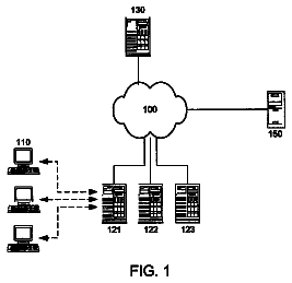
FIG. 1 is a schematic drawing illustrating a plurality of network devices coupled with a public network, a private network, and a management network, in accordance with one embodiment of the present invention;
FIG. 2 is an isometric view, illustrating a server rack, in accordance with one embodiment of the present invention;
FIG. 3 is a schematic drawing illustrating an example server chassis that includes clustered network devices; and
FIGS. 4-8 are schematic drawings illustrating example graphical user interface screens for monitoring and managing a cluster of network devices.
Detailed description of the drawings
Referring to FIG. 1, a high density, multiple server network is illustrated and generally designated by the reference number 30. Network 30 includes a plurality of network devices 32 mounted on a base 36 of a server chassis 38 and coupled with a public network 45, a private network 46 and a management network 47. In particular embodiments, network devices 32 may include server processing cards. Each server processing card may be configured to function similarly. Specifically, a server processing card may provide the functionality of a single board computer, which may be employed as a rack mounted server. Networks 45, 46 and 47 may be configured, maintained and operated independently of one another, and cooperate to provide is distributed functionality of network 30.
A network device 32 that includes a server processing card may be a single board computer upon which all of the requisite components and devices are mounted to enable network device 32 to function and operate as a server handling compute tasks. In the illustrated embodiment, each network device 32 within a particular chassis 38 shares a common passive midplane 34 through which all power and connectivity passes. Server chassis 38 is intended for rack mount in server rack 39 (See FIG. 2), and includes passive midplane 34 and all the associated network devices 32. In one embodiment, network device 32 includes a powerful computer that may be connected to the Internet and operable to store data (e.g., audio, video, data graphics and/or text files).
As illustrated, each network device 32 includes a printed circuit board 82, coupled with a central processing unit (CPU) 84, a disk drive 86, and a dynamic memory integrated circuit 88. Central processing unit 84 performs the logic, computational and decision making functions of processing card 32. Many types of central processing units with various specifications may be used within the teachings of the present invention. In the illustrated embodiment, CPU 84 includes a Crusoe 667 MHz CPU, as manufactured by Transmeta. In fact, many central processing units with comparable processing power to a 500 MHz, Pentium III, as manufactured by Intel, may be used within the teachings of the present invention. For example, the Crusoe TM 3200 with speeds in the range of 300-400 MHz, or TM 5400 with speeds in the range of 500-700 MHz, may also be used. Disk drive 86 includes electronics, motors, and other devices operable to store (write) and retrieve (read) data on a disk. In the illustrated embodiment, disk drive 86 includes a two and one-half inch IBM 9.5 mm notebook hard drive. A second two and one-half inch disk drive 87 may be installed upon a given network device 32. The use of disk drive 87 is optional, and increases the capacity and functionality of network device 32.
In accordance with a particular embodiment of the present invention, each network device 32 is coupled with a passive midplane 34. On its front face 35, passive midplane 34 includes a plurality of receptors 37 that facilitate the installation of network devices 32. In particular embodiments, passive midplane 34 includes twenty-four receptors 37 to couple to up to twenty-four network devices 32. The rear face of passive midplane 34 also includes a plurality of network interface card connectors. Passive midplane 34 is considered "passive" because it may be provided with no active components that can fail. Instead, passive midplane 34 includes the necessary wiring to connect each respective network device 32 with an appropriate network interface card 40, 48, and 67. Passive midplane 34 includes a printed circuit board with the appropriate printed circuitry to distribute data and power necessary for the operation of network 30. For example, passive midplane 34 distributes power to components of network devices 32 and network interface cards 40, 48, and 67. Additionally, passive midplane 34 distributes data and/or communication signals between network devices 32 and network interface cards 40, 48, and 67. As will be described in further detail with regard to FIGS. 4-8, passive midplane 34 "autosenses" network devices 32 and available receptors 37, to allow automatic configuration of networks via remote management system 70.
The rear face (not shown) of passive midplane 34 includes a pair of power supply mounting mechanisms which accommodate power supplies 280. Each power supply 280 includes enough power to operate a fully populated passive midplane 34, in the event that one of the two power supplies 280 fails. Accordingly, server chassis 38 may be offered and operated using a single power supply 280, with an optional upgrade to a second power supply 280. Since each power supply 280 is sized appropriately to operate an entire chassis 38, a single power supply 280 may be removed from chassis 38, without powering OFF server chassis 38, or affecting the operation of network 30.
In particular embodiments, power supplies 280 may be load balanced if power supplies 280 include "auto sensing" capabilities. Auto-sensing capabilities enable each power supply 280 to sense the load required of it. The printed circuitry associated with midplane 34 evenly distributes the necessary power consumption load between power supplies 280. Therefore, power supplies 280 will automatically supply one half of the necessary power (voltage) to midplane 34 when each power supply 280 is properly connected and fully operational. If service from one power supply 280 is diminished, or becomes unavailable, the other power supply 280 may sense this and supply the power necessary for passive midplane 34 to operate at fully capacity. In another embodiment, power supplies 280 and midplane 34 may be provided with the printed circuitry necessary to allow power supplies 280 to communicate with one another regarding their load sharing responsibilities, and report trouble and/or diminished capacity to one another. Power supplies 280 also include interfaces that allow management network interface card 68 and remote management system 70 to monitor voltage and temperature of each power supply 280.
A network interface card 40 couples passive midplane 34, and therefore network devices 32 with a public network switch 42, via communication link 44. In particular embodiments, network interface card 40 may support up to twenty-four independent server processing cards. Thus, communication link 44 may include twenty-four groups of two twisted pair category 5 cable, for a total of forty-eight different Ethernet connections, or ninety-six wires total. Public network switch 42 distributes data between network devices 32 and public network 45. The connection between public network switch 42 and network interface card 40 may be accomplished with high density Ethernet connectors. In particular embodiments, public network switch 42 may include a Cisco Catalyst 5500, an industry standard Ethernet switch, or a Black Diamond public switch, as manufactured by Extreme Networks. Throughout this specification, however, the term "switch" may be used to indicate any switch, router, bridge, hub, or other data/communication transfer point.
A high density connector 43 may be coupled with public switch 42 to facilitate communication between public switch 42 and communications link 44. In one embodiment, high density connector 43 may include an RJ-21 high density telco (telephone company) type connector for consolidating at least twelve 10/100/1000 megabits per second Ethernet connections through a single cable. The use of high density telco style connectors, like high density connector 43 allows the consolidation of twelve, twenty-four or forty-eight Ethernet connections, at a twelve to one ratio, through a single cable.
Communication link 44 is operable to provide gigabit Ethernet over fiber. In another embodiment, communication link 44 may include gigabit Ethernet over copper. The coupling between public switch 42 and network interface card 40 may be accomplished using a single communication link 44. However, in another embodiment a second communication link 44 may be provided to accomplish a redundant configuration. This allows a back-up communication link between public switch 42 and network interface card 40, in case of failure of the primary communication link. Accordingly, redundant fiber connections to public switch 42 or other high density data center switches capable of aggregating hundreds of gigabit connections in a single switch 42, are provided.
Public switch 42 is coupled with public network 45 over communications link 51. Public network 45 may include a variety of networks including, without limitation, local area networks (LANs), wide area networks (WANs), and/or Metropolitan Area Networks (MANs). In the illustrated embodiment, public network 45 may include the Internet. Communication link 51 may include a high bandwidth transport in order to serve a plurality of servers on an internet service provider (ISP) or application service provider (ASP). For example, and without limitation, communication link 51 may include a T3 or OC48 in a particular embodiment.
A second network interface card 48 is coupled with passive midplane 34 and distributes data to a private network switch 50 via communication link 52. Similar to public network switch 42, private network switch 50 may also include either a Catalyst 5500, as manufactured by Cisco, or a Black Diamond, as manufactured by Extreme Networks. A high density connector 53 may be provided to facilitate communication between private network switch 50 and communications link 52, and ultimately, network interface card 48. In a particular embodiment, high density connector 53 may include an RJ-21 high density telco type connector for consolidating at least twelve 10/100/1000 megabits per second Ethernet connections through a single cable. As previously described, the use of high density telco style connectors, like high density connector 53 allows the consolidation of twelve, twenty-four or forty-eight Ethernet connections at a twelve to one ratio, through a single cable.
Private network switch 50 is coupled with a plurality of "back office" network applications including storage server 54, applications server 56, database server 58 and legacy systems 60 through communication links 62, 63, 64 and 65, respectively. Throughout this specification, "back office" will be used to indicate operations, management and support tasks used to support the operation of network devices 32, which are accomplished at remote locations from server chassis 38. Communication links 62-65 provide private 10/100/1000 megabits per second Ethernet supporting various high volume business transaction processing systems (HVBTPS). Storage server 54 provides mass storage to support server processing cards of various users. This is a private connection because server 54 is not linked directly to public network 45. Storage server 54 provides network attached storage (NAS). Application server 56 may be rented, or provided by an application service provider (ASP). Database server 58 provides transaction processing, and legacy systems 60 may include various database servers.
Private network 46 may be configured to provide a plurality of "back-end" network applications. For example, private network 46 may provide end users with secure internet voicemail, internet fax, a "personal" server, electronic mail accounts, MP-3 servers and/or digital photo collection servers. In another embodiment, private network 46 may be configured to provide groupware and other associated applications. For example, private network 46 may include the necessary hardware and software to provide users of network 30 with "chat rooms" and other on-line meeting applications. Wireless Application Protocols (WAPs) applications may also be provided. In fact, the WAP applications may be synchronized to groupware associated with the network devices. Regardless, private network 46 is considered "private," because there is no physical connection between private network 46 and public network 45. Accordingly, security is provided to data and communications of private network 46 because private network 46 is protected from a security breach initiated from public network 45.
Passive midplane 34 is also coupled to remote management system 70 of management network 47 through a third network interface card 68. Network interface card 68 is coupled to management network 47 by communication link 71, which distributes data between passive midplane 34 and remote management system 70. One or more online/nearline memory storage devices, including non-volatile storage device 72 and secondary non-volatile storage device 74 communicate with management console 70 using communication links 76 and 78, respectively. Memory storage devices 72 and 74 communicate with one another through communication link 80. Remote management system 70, non-volatile storage device 72, and secondary non-volatile storage device 74 also provide in-line/near-line storage support for network devices 32. Storage devices 72 and 74 may include high capacity redundant array of inexpensive disks (RAID)/optical/tape subsystem controlled by hierarchical storage management software that enables automatic back-up and restoration of user data from all servers via remote management system 70.
As will be described in more detail with regard to FIGS. 4-8, remote management system 70 includes the ability to monitor, manage, back-up, restore, activate, and operate many of the components of high density server network 30. For example, an operator of a remote management system 70 can control all of the functions and operations of network devices 32. In particular embodiments, remote management system 70 includes control software and other applications that accomplish these functions and operations automatically, without operator intervention. For example, remote management system 70 may perform metering, including without limitation packet level metering, and bandwidth monitoring of network devices 32. Other characteristics and measurements which remote management system 70 collects, evaluates, and stores include operating data and other information regarding network devices 32.
Remote management system 70 identifies each network device 32 according to at least two identifiers. For example, during start-up of each network device 32, remote management system 70 is informed of a hardware address associated with each network device 32. The hardware address is analogous to the IP address assigned by the server to each client, in a client/server network system. The hardware address of each network device 32 may be referred to as the "logical" address of a particular network device 32.
Also during the startup of network devices 32, remote management system 70 is informed of a three digit rack/chassis/slot address identifier unique to each network device 32. The rack/chassis/slot address may also be referred to as the physical identifier, or physical address of a particular network device 32. The physical address allows remote management system 70 to identify a particular network device 32 in a manner which is more readily identifiable to an operator of remote management system 70 or other user of server network 30.
Remote management system 70 has the ability to provide a single point of management for thousands of servers. The servers under the control of remote management system 70 may include thousands of network devices 32. Thus, remote management system 70 includes various software, applications, and functionality that simplify and improve the operation of associated servers, including without limitation network devices 32. Management software, applications, and functionality associated with remote management system 70 typically reside on a server.
A web browser based, graphical user interface 69 associated with remote management system 70 provides the operator of management network 47 with a user-friendly, easy to read overview of operational functions in graphical formats, suitable for "at a glance" monitoring and diagnosis. This includes an intuitive user interface for controlling basic functionality of servers on a single server level. Accordingly, a network operator or administrator may add, delete, configure, or modify virtual servers and/or network devices 32. Similarly, remote management system 70 may be used to add, delete, configure, and modify users who are granted access to network devices 32 of public network 45. Example graphical formats will be described in more detail with regard to FIGS. 4-8. Remote management system 70 also provides operations, administration, management, and provisioning (OAM&P) functionality to the network administrator. Traffic metering and measurement (TM&M) and performance measurements are also collected, stored, analyzed and maintained by remote management system 70.
Similar to private network 46, management network 47 is considered a "private" network. Since there is no physical connection between management network 47 and public network 45, management network 47 is protected from a security breach initiated from public network 45.
FIG. 2 illustrates a server rack 39 including a plurality of server chassis 38. For purposes of this specification, a standard industry rack has the approximate dimensions nineteen inches wide by six feet high by thirty to thirty-tour inches deep. In a particular embodiment, each server chassis 38 consumes a total of 3 U (1 U=1.75 inches) of space. Accordingly, as many as fourteen server chassis 38 may be installed in an industry standard 42 U rack. The user of server processing card 32 having two, two and one-half inch disk drives allows for the installation of three hundred and thirty-six servers within an industry standard rack having 42 U of usable interior space (standard industry rack). In alternative embodiments, chassis may be provided that are 7 U or greater, and as small as 1 U.
Server rack 39 is configured to provide a user friendly operating environment. For example, server rack 39 may be co-located at the physical location of an internet service provider (ISP) or an applications service provider (ASP). Moreover, due to the ease of use and operation, unsophisticated employees of the ISP/ASP can easily operate and maintain all of the components associated with server rack 39. The design and configuration of server processing cards 32 accommodate an extremely low total cost of ownership (TCO).
To ease the management and maintenance of the many network devices 32 in a rack 39, multiple network devices 32 within a rack 39 or chassis 38 may be clustered. For example, a "cluster" of server processing cards includes those server processing cards that are joined logically and/or physically in order to provide a sealed level of service to a user. FIG. 3 illustrates an example server chassis 38 that includes clusters 100 of network devices 32. During operation, cluster 100 may also be managed as an entity. Cluster 100 may be expanded and reconfigured to meet changing requirements of the system. Network devices 32 may be removed or added from cluster 100. Because cluster 100 operates as an entity, the attributes associated with a cluster 100 may be automatically applied to network devices 32 added to a cluster 100. Where desirable, the imaging and syncing of new network devices 32 may be automated.
A cluster 100 functions as a single system for performing compute tasks. Accordingly, each cluster 100 may be used as a productive tool to reduce the costs associated with the creation, maintenance, and management of network devices 32. Specifically, network devices 32 in a particular cluster 100 may have one or more attributes associated with the cluster 100. The attributes may be common to each network device 32 in the particular cluster 100. Additionally, the attributes may be unique to the cluster 100 as a whole. During creation of each cluster 100, the attributes associated with a cluster 100 may include configuration actions that are automatically applied to every network device 32 in the cluster 100. Such attributes may include a name identifying the cluster 100, the designation of a cluster manager, the type of interconnect used for the cluster 100, an image identifying software to be associated with the cluster 100, and any other attribute unique to the cluster 100. The attributes that may be associated with a cluster 100 will be discussed in more detail with regard to FIGS. 4-9.
As illustrated, server chassis 38 includes two defined clusters 100a and 100b. Cluster 100a includes five active network devices 32, such as server processing cards, in positions four through eight of server chassis 38. Cluster 100b includes two network devices 32 in positions fifteen and sixteen of server chassis 38. Although clusters 100a and 100b are illustrated as including five and two network devices 32, respectively, a cluster 100, may include any appropriate number of network devices 32. For example, a single cluster 100 may be comprised of tens of server processing cards or as many as hundreds or thousands of server processing cards. Thus, a cluster 100 may include server processing cards from a single chassis 38 or multiple chassis 38 within rack 39. Additionally, cluster 100 may include server processing cards from multiple racks 39.
As illustrated, chassis 38 includes additional network devices 32 that are not "clustered." For example, the network device 32 in position one of chassis 38 is designated a control tower 102. Control tower 102 operates to manage network devices 32 and clusters 100. In particular embodiments, each chassis 38 within server rack 39 may include a control tower 102 that operates to manage the network devices 32 and any clusters 100 in the particular chassis 38. In other embodiments, a single server rack 39 may include only one control tower 102. Thus, the management operations performed by control tower 102 need not be limited to the particular server chassis 38 in which control tower 102 is located. Further, a control tower 102 located in server rack 39 may also operate to perform management operations on network devices 32 and clusters 100 in other server racks 39. Although control tower 102 is typically independent of any defined clusters 100, control tower 102 may include a network device 32 that is grouped in a cluster 100.
Chassis 38 may also include network devices 32 that run independently of clusters 100. For example, chassis 38 includes network devices 32 in positions nine through fourteen, seventeen through eighteen, and twenty-two through twenty-three, which are not defined to clusters 100a and 100b. Such network devices 32, though not designated to a cluster 100, may be available for designation to an existing cluster 100a or 100b or to a new cluster as the needs of system 30 are expanded. Alternatively, one or more network devices 32 in chassis 38 may be designated as protected. A protected position is one that cannot be designated to a cluster. Accordingly, network devices 32 that are coupled to protected receptors 37 are not available for designation to clusters 100a or 100b or to a new cluster. In the illustrated chassis 38, positions 2 and 3 are protected positions. Protected nodes 104 may be reserved for administrative functions.
As illustrated, chassis 38 also includes one or more unoccupied receptors 37. An unoccupied receptor 37 is a receptor 37 that is not coupled to a network device 32 but may be available to be coupled to a network devices 32. As illustrated, positions nineteen, twenty, twenty-one, and twenty-four of chassis 38 include unoccupied receptors 37. As will be described in more detail, with regard to FIG. 5, one or more of these available positions may be pre-registered for a cluster 100. Accordingly, an unoccupied receptor 37 may be designated as a receptor 37 belonging to a defined cluster 100a or 100b even though the receptor 37 is currently vacant. Because each cluster is managed and configured as an entity, the attributes associated with cluster 100 may also be attributed to the pre-registered receptor 37. In this manner, resources in chassis 38 may be reserved and automatically configured upon future expansion of defined clusters 100a or 100b.
As previously described, management network interface card 68 and remote management system 70 include the ability to monitor and manage components of network 30. Accordingly, various measurements and characteristics regarding the functionality and operation of clusters 100 may be collected, stored, analyzed, and maintained using network management card 68 and remote management system 70. Remote management system 70 includes a graphical interface 69 which displays collected and stored information regarding the operation of clusters 100. FIGS. 4-9 illustrate example graphical interface screens that may be displayed to a user to assist the user in the management, monitoring, and creation of clusters 100. The format of the information displayed in the graphical interface screens is merely exemplary. It is understood that the information displayed on the graphical interface screens may be in any format appropriate for conveying information about the functionality and operation of clusters 100 to the user.
The embedded circuitry of network devices 32 transfers the information, at predetermined intervals, through passive midplane 34 to management network interface card 68. This information is captured and stored within remote management system 70 for further processing. Remote management system 70 includes the hardware and software components required to collect, store, and analyze this information. Remote management system 70 then operates to aggregate the information for each cluster 100 and displays the cluster information to the user for maintenance and management. Remote management system 70 may also include the ability to react to the cluster information collected.
Resource Aggregation
An aggregated overview of the cluster information may be displayed to the user to enable the user to manage a defined cluster 100 as an entity. FIG. 4 illustrates a graphical interface screen 400 that displays an aggregated overview of clusters 100 within chassis 38 or server rack 39. The aggregated overview may include information in the form of "snapshot" and historical measurements associated with clusters 100. Snapshot measurements include those measurements that represent the value at a given point in time. Historical information includes measurements that have been collected over time.
Graphical interface screen 400 includes columns associated with various attributes and characteristics related to each cluster 100. Name 402 identifies the name of each cluster 100 listed on graphical interface screen 400. For the illustrated example, graphical interface screen 400 includes information relating to two clusters, PBS and GeneKnome. For discussion purposes, PBS and GeneKnome correspond with clusters 100a and 100b of FIG. 3, respectively. Node 404 identifies the number of network devices 32 that are designated to a cluster 100. For example, graphical interface screen 400 indicates that cluster 100a has four network devices 32 coupled to receptors 37 that are designated to cluster 100a. Cluster 100b has three network devices 32 coupled to receptors 37 that are designated to cluster 100b. Master 406 identifies the physical address for the network device 32 that operates as the cluster manager for each cluster 100. As discussed above with regard to FIG. 1, the physical address may include a three digit identifier that identifies the rack, chassis, and receptor of the network device 32 operating as the cluster manager. As indicated by master 406, the particular network devices 32 operating as the cluster managers for clusters 100a and 100b have physical addresses of 10.0.0.4 and 10.0.0.15, respectively.
Graphical interface screen 400 also includes a column that summarizes the health 408 of each listed cluster 100. As illustrated, health 408 includes two indicators for each cluster 100a and 100b. The indicators are illustrated as including shaded bars that may proportionately reflect the health of clusters 100. Accordingly, a first shade may be used to indicate healthy nodes within cluster 100, and a second shade may be used to indicate unhealthy nodes in cluster 100. As illustrated, each shaded portion of the indicator also includes a number to display numerically the relative number of healthy and unhealthy nodes. Accordingly, graphical user interface screen 400 uses both a graphical and numerical format for displaying information to the user. However, graphical user interface screen 400 may use any appropriate format to convey information about the clusters 100 to the user. In particular embodiments, where graphical interface 69 is able to display graphical user interface screen 400 in color, the indicators may include variable colored bars. Thus, a first color may be used to indicate healthy nodes and a second color may be used to indicate unhealthy nodes.
First indicator summarizes the cluster health 410 for the particular cluster 100. Cluster health 410 may take into account whether the voltages on network devices 32 within the particular cluster 100 are correct, whether the fans for the particular cluster 100 are operating, and any other information specific to the operation of hardware supporting the cluster 100 on the server chassis 38. As described above, proportionately shaded or colored sections of cluster health 410 display the relative health of the nodes in the particular cluster. Because cluster health 410a and cluster health 410b each include only one shade, the user may easily determine that all network devices 32 in each cluster 100 are healthy. Additionally, cluster health 410a includes the numeral "4" to indicate that all four nodes, or network devices 32, in cluster 100a are healthy. Similarly, cluster health 410b includes the numeral "3" to indicate that all three nodes of cluster 100b are healthy.
Health 408 of graphical interface screen 400 also includes a second indicator reflecting image status 412 for each cluster 100. As will be described in greater detail below, an image may be associated or designated by the user for each network device 32 in chassis 38 and rack 39. Further, each network device 32 in a cluster 100 may be associated with the same image. The image may include an IP address and/or a physical location that identifies software that operates to configure the network devices 32 in the particular cluster 100. Accordingly, image status 412 may take into account whether the network devices 32 in a cluster 100 are associated with an operational image and/or any other information specific to the images designated for network devices 32 in cluster 100. As illustrated, image status 412 also includes a proportionately shaded or colored bar that includes a number within each proportionately shaded or colored section to indicate how many nodes, or network devices 32, are associated with an operational image and how many nodes are not associated with an operational image. For example, image status 412a indicates that all four nodes of cluster 100a are associated with an operational image. Similarly, image status 412b indicates that all three nodes of cluster 100b are associated with an operational image.
Graphical interface screen 400 also includes a column indicating the overall performance 414 of each cluster 100. Performance 414 provides snapshot information of the loads on the network devices 32 in a particular cluster 100. Multiple load indicators 416 may be used to summarize the ability of each cluster 100 to handle a given load. For example, the indicators 416a associated with cluster 100a indicate that all four network devices 32 designated to cluster 100a are able to handle a 1 m load, a 5 m load, and a 15 m load. Similarly, the indicators 416b associated with cluster 100b indicate that all three network devices 32 designated to cluster 100b are able to handle a 1 m load, a 5 m load, and a 15 m load. For each cluster 100, performance 414 may also include an indicator 418 summarizing the jobs running on cluster. Jobs reported include the resources the job is using and attributes of the job (e.g., execution host, submissions host, directories used, etc.). For example, indicator 418a indicates that there are currently 14 jobs in the queue for cluster 100a. The differently shaded or colored portions of indicator 418a indicates to the user, however, that only eight of the jobs are currently running. The remaining six jobs may be suspended or pending (e.g., green running, blue=pending, yellow=suspended). Because no jobs are reported for cluster 100b, however, graphical user interface screen 400 does not include an indicator 418 for cluster 100b.
Graphical interface screen 400 also includes a column indicating the overall utilization 420 of the hardware associated with each cluster 100. Specifically, indicators are used to indicate the utilization of specific pieces of information that are reported for the hardware of each cluster 100. Virtual memory indicators 422a and 422b summarize network devices 32 designated to each cluster 100a and 100b, respectively, that have available memory. Disk usage indicators 424a and 424b summarize the network devices 32 designated to each cluster 100a and 100b, respectively, that have disk memory availability. CPU utilization indicators 426a and 426b summarize the utilization of the CPUs associated with each network device 32 in clusters 100a and 100b, respectively. Interconnect TX indicators 428a and 428b summarize transmitted bits (Mb/s) for each cluster 100a and 100b, respectively. Interconnect RX indicators 430a and 430b summarize received bits (Mb/s) for each cluster 100a and 100b, respectively.
Graphical interface screen 400 also includes a column indicating alerts 432 for each cluster 100a and 100b. A symbol 434 or other indicator may be used in alert 432 to identify to the user whether any component of a cluster 100a or 100b has failed. Examples of a failure in a particular cluster 100 may include the overheating of a network device 32 in the particular cluster 100, a voltage irregularity within the cluster 100, or any other occurrence which may render a component of the cluster 100 to become partly or wholly inoperational. Different symbols 434 may be used to indicate the severity of the failure. For example, symbol 434a is an exclamation point enclosed in a triangle, which is a universally recognized symbol for a hazard. Thus, symbol 434a may predict a prospective failure within cluster 100a. In contrast, symbol 434b is an exclamation point surrounded by a circle which is a universally recognized symbol for a warning. Thus, symbol 434b may demonstrate to a user that a component of cluster 100b has already failed.
The description continues in the full USPTO document.
 Lapsed, fee not paid4 drawings