Background
1. Technical field
The technical field relates to an interchangeable lens including a plurality of operating units configured to operate an optical member, and a camera body to which the interchangeable lens is mountable.
2. Related art
A conventional interchangeable lens unit adopts a mechanism for mechanically driving an optical system such as a focus lens and a zoom lens. On the other hand, in recent years, there has been proposed a digital camera which drives an optical system by an electric actuator such as a motor (see, for example, WO 2009/041063). This conventional interchangeable lens unit can adjust zoom magnification.
In a digital camera to which an interchangeable lens primarily used for shooting still images (photos) is mountable, a ring-shaped rotation operating member (a so-called zoom ring) is provided around a lens barrel of the interchangeable lens in order to adjust zoom magnification. When a user rotates the zoom ring, the zoom magnification changes according to the amount of rotation of the zoom ring, and thus, the user can intuitively obtain a desired zoom magnification.
Meanwhile, in a video camera primarily used for shooting moving images, a switch type operating member (a so-called zoom lever) such as a lever or a button is provided in order to adjust zoom magnification. In such a video camera, the zoom magnification changes at a constant speed by the motorized zoom in which an actuator drives a zoom lens according to the on/off operation of the operating member. Therefore, a user can continuously change the zoom magnification at a constant speed.
A digital camera which includes an interchangeable lens and can shoot both moving images and still images becomes widely used in recent years. Such an interchangeable lens is considered to include both a zoom ring and a zoom lever as operating members for adjusting zoom magnification. However, using a digital camera to which an interchangeable lens including both a zoom ring and a zoom lever is mounted may cause occurrence of erroneous operation. For example, if, during operation of one of such operating members (e.g., the zoom lever), a user touches the other operating member (e.g., the zoom ring) at an unintentional timing, then the zoom magnification changes by the zoom ring and thus the user cannot adjust the zoom magnification as intended. Thus, when a plurality of operating members are provided on a digital camera, usability in terms of zoom magnification setting may not be good for a user of the camera.
Summary
In view of the above-described problem, an object is to provide an interchangeable lens and a camera body which implement a camera system providing a user of the camera with excellent usability in terms of zoom operation of the interchangeable lens including a plurality of operating members.
To solve the above-described problem, in a first aspect, an interchangeable lens mountable to a camera body includes: a zoom lens configured to adjust an angle of view of a subject image; a driver configured to move the zoom lens in an optical axis direction; a plurality of operating members configured to generate an operation signal for driving the driver according to operation performed by a user; a communication unit configured to receive, from the camera body, setting information for setting valid/invalid of at least one of the plurality of operating members; and a controller configured to control the driver. The controller drives the driver based on the operation signal from the operating member having been set to valid by the setting information received through the communication unit, and does not drive the driver based on the operation signal from the operating member having been set to invalid by the received setting information.
To solve the above-described problem, in a second aspect, a camera body to which an interchangeable lens including a plurality of operating members configured to drive a zoom lens is mountable, includes: an imaging unit configured to capture a subject image inputted through the interchangeable lens to generate image data; a setting unit configured to set setting information for setting valid/invalid of at least one of the plurality of operating members of the interchangeable lens; and a communication unit configured to send the setting information to the interchangeable lens.
According to the above aspects, the camera body sets setting information for setting valid/invalid state of at least one operating member (e.g., a zoom ring) among a plurality of operating members (e.g., a zoom ring and a zoom lever) based on user's operation, and the interchangeable lens controls the driver for the zoom lens based on the setting information. By this, for example, when a user wants to adjust zoom magnification by operating the zoom lever, by setting the zoom ring to invalid, the zoom magnification can be prevented from being unintentionally changed due to the user accidentally touching the zoom ring. Thus, an interchangeable lens operable to set the zoom magnification with excellent usability for a user, and a camera body to which the interchangeable lens is mountable can be implemented.
Brief description of drawings
FIG. 1 is an external view of a digital camera of a first embodiment.
FIG. 2 is a rear view of the digital camera of the first embodiment.
FIG. 3 is an electrical configuration diagram of the digital camera of the first embodiment.
FIGS. 4A, 4B, 4C and 4D are diagrams showing examples of display screen on a liquid crystal monitor of a camera body in the first embodiment, and FIG. 4A is a diagram showing an exemplary display screen at shooting mode, FIG. 4B is a diagram showing an exemplary display of a menu setting screen, FIG. 4C is a diagram showing an exemplary display of a detailed motorized zoom settings screen, and FIG. 4D is a diagram showing an exemplary display screen at zoom operating mode.
FIG. 5 is a flowchart showing an initial operation of the digital camera of the first embodiment.
FIG. 6 is a flowchart showing a zoom operation performed when operation of a zoom ring is set to valid in the first embodiment.
FIG. 7 is a flowchart showing a zoom operation performed when operation of the zoom ring is set to invalid in the first embodiment.
Detailed description of preferred embodiments
First Embodiment
In a digital camera of a first embodiment, an interchangeable lens includes a plurality of operating members (specifically, a zoom ring and a zoom lever) for driving a zoom lens. A camera body sets setting information for indicating a valid/invalid state of at least one operating member (in the present embodiment, the zoom ring) among the plurality of operating members of the interchangeable lens, based on user's operation, and the interchangeable lens controls a zoom lens driver based on the setting information. By this, the zoom ring can be set to invalid. For example, when a user wants to adjust zoom magnification by operating the zoom lever, the zoom magnification can be prevented from being unintentionally changed due to the user accidentally touching the zoom ring. Thus, according to the present embodiment, an interchangeable lens with improved user usability in terms of zoom magnification setting and a camera body to which the interchangeable lens is mountable can be implemented.
1. Configuration
1-1. Configuration Overview
An overview of a configuration of a digital camera of the first embodiment will be described.
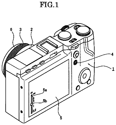
FIG. 1 is an external view of a digital camera 100 of the first embodiment. As shown in FIG. 1, the digital camera 100 includes a motorized interchangeable lens 101 and a camera body 102 to which the motorized interchangeable lens 101 is mountable. The motorized interchangeable lens 101 is an interchangeable lens configured to change zoom magnification by controlling a zoom lens driver (e.g., an actuator) according to operation performed by a user. The motorized interchangeable lens 101 includes both a zoom ring 115 and a zoom lever 118 as operating members for controlling the zoom lens driver. When the zoom ring 115 is operated by the user, the motorized interchangeable lens 101 performs control of a zoom lens by driving the zoom lens driver according to the operation of the zoom ring 115. In addition, when the zoom lever 118 is operated by the user, the motorized interchangeable lens 101 performs control of the zoom lens by driving the zoom lens driver according to the operation of the zoom lever 118.
The camera body 102 includes a release button 160. When the camera body 102 accepts operation of the release button 160 performed by the user, the camera body 102 can notify the motorized interchangeable lens 101 of a control signal to perform autofocus operation or can perform shooting operation of a subject image formed through the motorized interchangeable lens 101.
FIG. 2 is a rear view of the digital camera 100 (the camera body 102). The camera body 102 includes, at its rear portion, a liquid crystal monitor 163, a touch panel 162, a camera-side operating unit 170 (including a center button 204 and a cross button 205), and the like. The camera body 102 accepts an operation performed by the user on the touch panel 162 and the camera-side operating unit 170 and performs various controls according to the contents of the operation.
FIG. 3 is a diagram showing an electrical configuration of the digital camera 100 (the motorized interchangeable lens 101 and the camera body 102). The motorized interchangeable lens 101 includes a lens controller 120, a lens mount 130, an optical system including a focus lens 110 and a zoom lens 112, a focus lens driver 111, a zoom lens driver 113, a diaphragm 116, a diaphragm driver 117, the zoom ring 115, the zoom lever 118, a DRAM 121, a flash memory 122, and the like. The camera body 102 includes a camera controller 153, a body mount 140, a CMOS image sensor 150, a timing generator (TG) 151, an analog front end (AFE) 152, the liquid crystal monitor 163, the touch panel 162, the release button 160, the camera-side operating unit 170, a power supply 154, a DRAM 155, a flash memory 156, a card slot 165, a memory card 164, and a horizontal and vertical sensor 166.
1-2. Configuration of Each Component of Motorized Interchangeable Lens
A configuration of each component of the motorized interchangeable lens 101 will be described.
The lens controller 120 controls the entire motorized interchangeable lens 101. When the lens controller 120 accepts operation of the zoom ring 115 by a user, the lens controller 120 controls the zoom lens driver 113 to drive the zoom lens 112. In addition, when the lens controller 120 accepts operation of the zoom lever 118 by the user, the lens controller 120 controls the zoom lens driver 113 to drive the zoom lens 112. The lens controller 120 is connected to the DRAM 121 and the flash memory 122 and can write or read information to/from the DRAM 121 and the flash memory 122 as necessary. In addition, the lens controller 120 can communicate with the camera controller 153 through the lens mount 130. Note that the lens controller 120 may include a hard-wired electronic circuit or may include a microcomputer using a program, and the like.
The lens mount 130 is a connecting member for mechanically and electrically connecting, together with the body mount 140 included in the camera body 102, the motorized interchangeable lens 101 to the camera body 102. When the motorized interchangeable lens 101 and the camera body 102 are mechanically and electrically connected, the lens controller 120 and the camera controller 153 go into a communicable state.
The DRAM 121 is used as a working memory when performing various controls by the lens controller 120. The flash memory 122 stores a program, parameters, lens data, and the like, which are used when various controls are performed by the lens controller 120. In the present embodiment, when zoom ring operation setting information indicating a zoom ring operation acceptance allowed/not allowed setting state (i.e., the valid/invalid of operation of the zoom ring 115) is sent to the motorized interchangeable lens 101 from the camera body 102, the zoom ring operation setting information is stored in the flash memory 122.
The focus lens 110 is a lens for changing the focus state of a subject image which is incident on the optical system of the motorized interchangeable lens 101 and formed on the CMOS image sensor 150. The lenses included in the focus lens 110 may be any in number and of any group. The focus lens driver 111 drives the focus lens 110 to move back and forth along an optical axis of the optical system, based on a control signal notified from the lens controller 120. Note that the focus lens driver 111 can be implemented by, for example, a stepping motor, a DC motor, or an ultrasonic motor.
The zoom lens 112 is a lens for changing the magnification of a subject image formed by the optical system of the motorized interchangeable lens 101. The lenses included in the zoom lens 112 may be any in number and of any group. The zoom lens driver 113 drives the zoom lens 112 to move back and forth along the optical axis of the optical system, based on a control signal notified from the lens controller 120. Note that the zoom lens driver 113 can be implemented by, for example, a stepping motor, a DC motor, or an ultrasonic motor.
The diaphragm 116 is composed of a plurality of mechanical blades such that they can be opened and closed. The diaphragm 116 is a regulating member capable of regulating the amount of light entering the optical system of the motorized interchangeable lens 101. The diaphragm driver 117 changes the open/closed state of the mechanical blades of the diaphragm 116, based on a control signal notified from the lens controller 120. Note that the diaphragm driver 117 can be implemented by, for example, a stepping motor, a DC motor, or an ultrasonic motor.
The zoom ring 115 is an operating member provided on the exterior of the motorized interchangeable lens 101. The zoom ring 115 is configured to rotate relative to the motorized interchangeable lens 101. The rotation position and rotation speed of the zoom ring 115 are detected by a detector (not shown) and notified to the lens controller 120. The lens controller 120 supplies a drive control signal (zoom control signal) to the zoom lens driver 113, based on the notified rotation position and rotation speed of the zoom ring 115.
The zoom lever 118 is an operating member provided on the exterior of the motorized interchangeable lens 101. As one example, the zoom lever 118 may be a three-position toggle switch (SW). When the lens controller 120 detects that the zoom lever 118 has been moved, the lens controller 120 supplies a drive control signal (zoom control signal) to the zoom lens driver 113, based on a direction in which the zoom lever 118 has been moved. In this case, the zoom control signal is a signal instructing the zoom lens driver 113 to drive the zoom lens 112 at the maximum speed in a drivable range, and allows to perform drive at a constant speed compared to a zoom control signal generated based on operation of the zoom ring 115.
Note that the lens controller 120 may detect a direction and an angle in/at which the zoom lever 118 has been moved, and impose a speed limit on the zoom lens driver 113 based on the detected direction and angle. In this case, the zoom magnification changes at a constant speed which is determined by the direction and angle in/at which the zoom lever 118 has been moved.
1-3. Configuration of Each Component of Camera Body
A configuration of each component of the camera body 102 will be described.
The camera controller 153 controls the entire digital camera 100 (e.g., the CMOS image sensor 150 and the like) according to instructions from the release button 160 and the camera-side operating unit 170. The camera controller 153 notifies the timing generator (TG) 151 of a vertical synchronizing signal. In parallel with this, the camera controller 153 generates an exposure synchronizing signal, based on the vertical synchronizing signal. The camera controller 153 periodically and repeatedly notifies the lens controller 120 of the generated exposure synchronizing signal through the body mount 140 and the lens mount 130. The camera controller 153 is connected to the DRAM 155 and the flash memory 156 and can write or read information to/from the DRAM 155 and the flash memory 156 as necessary. The camera controller 153 may include a hard-wired electronic circuit or may include a microcomputer using a program, and the like.
The DRAM 155 is used as a working memory when performing various controls by the camera controller 153. The flash memory 156 stores a program, parameters, and the like, which are used when various controls are performed by the camera controller 153. In the present embodiment, the flash memory 156 stores zoom ring operation setting information indicating a zoom ring operation acceptance allowed/not allowed setting state (i.e., the valid/invalid of operation of the zoom ring 115).
The CMOS image sensor 150 captures a subject image incident thereon through the motorized interchangeable lens 101 and thereby generates image information. The AFE 152 converts the image information generated by the CMOS image sensor 150 from data in analog form to data in digital form. The camera controller 153 performs various types of image processing on the image information digitized by the AFE 152. The various types of image processing as used herein include, for example, a gamma correction process, a white balance correction process, a flaw correction process, a YC conversion process, an electronic zoom process, and a JPEG compression process, but are not limited thereto. In addition, instead of the CMOS image sensor 150, other imaging devices, e.g., an NMOS image sensor and a CCD image sensor, can also be used.
The CMOS image sensor 150 operates at timing which is controlled by the TG 151. The operations of the CMOS image sensor 150 controlled by the TG 151 include a still image capturing operation, a through image capturing operation, a data transfer operation, an electronic shutter operation, and the like. A through image is mainly a moving image and is displayed on the liquid crystal monitor 163 in order to determine a composition for capturing a still image.
The liquid crystal monitor 163 is disposed at the rear of the camera body 102 and displays an image represented by image information for display processed by the camera controller 153. The liquid crystal monitor 163 can selectively display both a moving image and a still image. In addition to images, the liquid crystal monitor 163 can display setting conditions of the entire digital camera 100 and the like. Although, in the present embodiment, the liquid crystal monitor 163 is provided as an example of a display unit, other display units such as an organic EL display may be used.
The touch panel 162 is provided on a surface of the liquid crystal monitor 163, and generates information about an electrode position on the touch panel 162 touched by the user. The touch panel 162 calculates, based on the information about the electrode position, the coordinates of a position on the touch panel 162 touched by the user and notifies the camera controller 153 of the coordinates of the position.
The body mount 140 is a connecting member for mechanically and electrically connecting, together with the lens mount 130 included in the motorized interchangeable lens 101, the motorized interchangeable lens 101 to the camera body 102. When the motorized interchangeable lens 101 and the camera body 102 are mechanically and electrically connected, the lens controller 120 and the camera controller 153 go into a communicable state. The body mount 140 notifies the lens controller 120 of an exposure synchronizing signal and other control signals which are received from the camera controller 153, through the lens mount 130. In addition, the body mount 140 notifies the camera controller 153 of a signal received from the lens controller 120 through the lens mount 130.
The power supply 154 supplies power to be consumed by the digital camera 100. The power supply 154 may be, for example, a dry battery or a rechargeable battery. Alternatively, the power supply 154 may supply power supplied from an external source through a power cord, to the digital camera 100. When the power supply 154 is turned on, the camera controller 153 supplies power to the entire camera body 102. In addition, the camera controller 153 supplies power to the motorized interchangeable lens 101 through the body mount 140 and the lens mount 130. The lens controller 120 supplies power to the entire motorized interchangeable lens 101.
The card slot 165 is a connector which can allow the memory card 164 to be inserted thereinto and removed therefrom. The card slot 165 can connect the memory card 164 electrically and mechanically. Note that the card slot 165 may have the function of controlling the memory card 164.
The memory card 164 is an external memory including therein a storage unit such as a flash memory. The memory card 164 can store data such as image information processed by the camera controller 153. In addition, the memory card 164 can output data such as image information stored therein. The image information outputted from the memory card 164 is processed by the camera controller 153 and is played back and displayed on, for example, the liquid crystal monitor 163.
The release button 160 accepts a user's operation. The release button 160 can accept two-level, half press and full press operations. By the user performing the half-press operation on the release button 160, the camera controller 153 performs autofocus operation. In addition, by the user performing the full-press operation on the release button 160, the camera controller 153 stores image information generated according to the timing of the full-press operation, in the memory card 164.
The camera-side operating unit 170 is a generic term for operating members including the aforementioned center button 204 and cross button 205. The camera-side operating unit 170 may includes a switch which switches between MF (manual focus) and AF (autofocus). When the camera-side operating unit 170 accepts operation performed by the user, the camera controller 153 performs various controls according to the content of an instruction based on the operation performed by the user.
The horizontal and vertical sensor 166 detects whether the orientation of the camera body 102 is a vertical orientation or a horizontal orientation (an erect state). The horizontal and vertical sensor 166 sends the detected orientation to the camera controller 153.
1-4. Valid/Invalid Setting for Zoom Ring
The zoom setting mode of the motorized interchangeable lens 101 will be described. FIGS. 4A to 4D are diagrams showing exemplary displays on the liquid crystal monitor 163 of the camera body 102.
FIG. 4A is a diagram showing an example of display screen in a normal state of the liquid crystal monitor 163 when the digital camera 100 is set to a shooting mode for shooting an image.
When the user performs various settings of the digital camera 100, the user presses the center button 204 of the camera body 102. When the camera controller 153 detects the pressing of the center button 204, the camera controller 153 switches the display content on the liquid crystal monitor 163 from the display screen shown in FIG. 4A to the display screen shown in FIG. 4B. FIG. 4B shows an example of a display of a menu setting screen on which various settings of the digital camera 100 can be changed. On the menu setting screen, the user can set, for example, the focus mode to autofocus mode or manual focus mode.
When the motorized interchangeable lens 101 is mounted to the camera body 102, a motorized zoom setting item L001 which is displayed as "power zoom" is displayed on the menu setting screen shown in FIG. 4B. Specifically, when a motorized interchangeable lens which changes zoom magnification by controlling the zoom lens driver 113 according to operation performed by the user, such as the motorized interchangeable lens 101 of the present embodiment, is mounted to the camera body 102, the camera controller 153 detects the mounted state and displays the motorized zoom setting item L001. On the other hand, when a different interchangeable lens from such a motorized interchangeable lens is mounted, the motorized zoom setting item L001 is not displayed.
When the motorized zoom setting item L001 is selected by the user operating the camera-side operating unit 170 or the touch panel 162, the camera controller 153 changes the display content on the liquid crystal monitor 163 from the display screen shown in FIG. 4B to the display screen shown in FIG. 4C where detailed settings for motorized zoom can be performed. On the detailed motorized zoom settings screen shown in FIG. 4C, the camera controller 153 displays a zoom ring operation setting item L002 for setting whether to invalidate or validate operation of the zoom ring 115 of the motorized interchangeable lens 101. At this time, the camera controller 153 reads zoom ring operation setting information stored in the flash memory 156, and displays on/off of the zoom ring operation setting item L002 based on the read zoom ring operation setting information. The zoom ring operation setting information indicates whether to validate or invalidate operation of the zoom ring 115 performed by the user, and takes either value, "on" or "off". FIG. 4C shows exemplary display provided when the zoom ring operation setting information is "off".
When the zoom ring operation setting item L002 is selected by the user operating the camera-side operating unit 170 or the touch panel 162, the camera controller 153 switches the zoom ring operation acceptance allowed/not allowed setting state. Specifically, when the zoom ring operation acceptance allowed/not allowed setting state is "on", the state is changed to "off", and when the state is "off", the state is changed to "on". Along with this change, the camera controller 153 stores zoom ring operation setting information indicating the changed zoom ring operation acceptance allowed/not allowed setting state, in the flash memory 156, and notifies the motorized interchangeable lens 101 of the zoom ring operation setting information. As such, the user can select whether to invalidate or validate operation of the zoom ring 115 of the motorized interchangeable lens 101, by performing the setting of switching as to whether to allow zoom ring operation acceptance.
FIG. 4D is a diagram showing an exemplary display provided upon zoom operation. When the zoom lens 112 is driven by operating the zoom ring 115 or the zoom lever 118, zoom focal length information 300 indicating a zoom focal length is displayed as shown in FIG. 4D. In FIG. 4D, in order for the user to recognize the currently set motorized zoom magnification, the zoom focal length information 300 including a focal length scale 301 and an index 303 indicating the current zoom focal length is displayed.
2. Operation
2-1. Operation Overview
An overview of the operation of the digital camera 100 of the first embodiment will be described. When the power supply 154 to the camera body 102 is switched to an ON state by the user operating a power switch (not shown) of the camera body 102 with the motorized interchangeable lens 101 mounted to the camera body 102, power supply and various initial settings are performed.
The camera body 102 reads the zoom ring operation setting information stored in the flash memory 156 and sends the zoom ring operation setting information to the motorized interchangeable lens 101. The motorized interchangeable lens 101 mounted to the camera body 102 determines whether to validate or invalidate operation to be performed on the zoom ring 115, according to the zoom ring operation setting information obtained from the camera body 102.
The user of the digital camera 100 can set whether to allow acceptance of operation of the zoom ring 115 of the motorized interchangeable lens 101, by operation performed on the camera-side operating unit 170 or touch panel 162 of the camera body 102. When the setting of switching as to whether to allow acceptance of operation of the zoom ring 115 is performed by operation of the camera body 102, the camera body 102 sends zoom ring operation setting information to the motorized interchangeable lens 101. The motorized interchangeable lens 101 switches whether to validate or invalidate operation of the zoom ring 115, according to the information from the camera body 102.
The initial operation and zoom operation of the motorized interchangeable lens 101 and the camera body 102 will be described in detail below step by step.
2-2. Initial Operation Performed when the Motorized Interchangeable Lens is Mounted to the Camera Body
Initial operation performed when the motorized interchangeable lens 101 is mounted to the camera body 102 will be described using FIG. 5. FIG. 5 is a sequence chart for an initial operation for imaging preparation at power-on of the digital camera 100. When a user turns on the power supply 154 of the camera body 102 with the motorized interchangeable lens 101 mounted to the camera body 102 (S300), the power supply 154 supplies power to the motorized interchangeable lens 101 through the body mount 140 and the lens mount 130 (S301). By this, power is supplied to each component of the motorized interchangeable lens 101 (S302).
Then, the camera controller 153 requests the lens controller 120 to send authentication information of the motorized interchangeable lens 101 (S303). The authentication information of the motorized interchangeable lens 101 includes information about whether the interchangeable lens has been mounted to the camera body 102 (e.g., whether the motorized interchangeable lens 101 is being mounted) and information about whether accessories are being attached to the motorized interchangeable lens 101. The lens controller 120 responds to the lens authentication request from the camera controller 153 (S304). By this, the camera controller 153 completes the lens authentication and can grasp whether the motorized interchangeable lens 101 is being mounted to the camera body 102 and whether accessories such as a teleconverter lens and a wide converter lens are being attached to the motorized interchangeable lens 101 (S305).
Then, the camera controller 153 requests the lens controller 120 to perform initialization operation (S306). In response to this, the lens controller 120 performs initialization operation such as resetting the focus lens 110, resetting the zoom lens 112, and resetting the diaphragm 116 (S307). The lens controller 120 sends a response indicating that the lens initialization operation has been completed, to the camera controller 153 (S308). By this, the camera controller 153 can grasp that the motorized interchangeable lens 101 has been initialized (S309).
Then, the camera controller 153 requests the lens controller 120 to send lens data (S310). The lens data is stored in the flash memory 122 of the motorized interchangeable lens 101.
In response to the lens data request from the camera controller 153, the lens controller 120 reads lens data from the flash memory 122 (S311). The lens controller 120 sends, as a response, the read lens data to the camera controller 153 (S312). The lens data includes characteristic values specific to the motorized interchangeable lens 101, such as lens name, F-number, zoom controllable range, focus controllable range, and information about operating members. In addition, the lens data includes information about whether the mounted interchangeable lens has a motorized zoom function (whether, in the mounted interchangeable lens, the zoom lens 112 is driven in a motorized manner by the zoom lens driver 113 rather than being driven in mechanical conjunction with user's operation). By the camera controller 153 obtaining information about whether the mounted interchangeable lens has the motorized zoom function and information about operating members (the types of operating members provided on the motorized interchangeable lens 101) from the lens controller 120, the camera controller 153 can grasp information about whether the mounted interchangeable lens has the motorized zoom function and about operating members. The motorized interchangeable lens 101 of the present embodiment includes two operating members relating to the motorized zoom function, the zoom ring 115 and the zoom lever 118. Therefore, the lens data includes, as information about operating members, information indicating that the motorized interchangeable lens 101 includes the zoom ring 115 and the zoom lever 118. If the camera body 102 supports motorized zoom, then the camera controller 153 can perform various controls for the motorized zoom of the motorized interchangeable lens 101. In addition, if the camera body 102 supports the operating members of the motorized interchangeable lens 101, then the camera controller 153 can perform control of whether to allow operation of the operating members provided on the mounted motorized interchangeable lens 101. By the above-described operation, the camera controller 153 completes obtaining of the lens data of the mounted motorized interchangeable lens 101 (S313).
If the camera controller 153 determines, from the obtained lens data, that the mounted interchangeable lens supports motorized zoom and has a plurality of operating members which can operate zoom magnification (in the present embodiment, the zoom ring 115 and the zoom lever 118), then the camera controller 153 operates in the following manner. Specifically, the camera controller 153 reads zoom ring operation setting information which is stored in the flash memory 156 and which is set by a user who has used the digital camera 100 last time (S314). The zoom ring operation setting information indicates a setting state as to whether to accept operation of the zoom ring 115 provided on the motorized interchangeable lens 101. The camera controller 153 notifies the motorized interchangeable lens 101 of the read zoom ring operation setting information (S315). In response to the notification of the zoom ring operation setting information from the camera body 102, the motorized interchangeable lens 101 sets operation of the zoom ring 115 to valid or invalid, according to the notification (S316). The example in FIG. 5 shows the case in which operation of the zoom ring 115 is set to invalid. In this case, even if the zoom ring 115 is operated by the user, the zoom lens 112 is not driven. The lens controller 120 stores the zoom ring operation setting information in the flash memory 122.
When the camera body 102 grasps the lens data of the motorized interchangeable lens 101 mounted thereto and the motorized interchangeable lens 101 completes the setting of whether to allow operation of the zoom operating member, the digital camera 100 goes into an imageable state. In this state, the camera controller 153 periodically requests the lens controller 120 to send lens state data representing the state of the motorized interchangeable lens 101 (S317). The lens state data includes, for example, information on the zoom focal length by the zoom lens 112, information on the position of the focus lens 110, information on the aperture value of the diaphragm 116, zoom ring operation information indicating that the zoom ring 115 has been operated, and zoom lever operation information indicating that the zoom lever 118 has been operated. The zoom ring operation information includes information on whether the rotation position of the zoom ring 115 has been changed, the current rotation position and rotation speed, and the like. In response to this request, the lens controller 120 sends, as a response, requested lens state data to the camera controller 153 (S318).
By the camera body 102 and the motorized interchangeable lens 101 performing requests for necessary data and responses thereto in the above-described manner, the camera body 102 and the motorized interchangeable lens 101 complete the initial operation.
2-3. Zoom Control Performed when Operation of the Zoom Ring is Set to Valid
Zoom control performed when the zoom ring 115 of the motorized interchangeable lens 101 is operated will be described. First, zoom control performed when operation of the zoom ring 115 is set to valid will be described. FIG. 6 is a sequence chart for zoom control performed when operation of the zoom ring 115 is set to valid and thereafter the zoom ring 115 is operated.
When a user of the digital camera 100 wants to perform zoom operation with the zoom ring 115 of the motorized interchangeable lens 101, the user sets operation of the zoom ring 115 to valid on a menu setting screen of the camera body 102 (the motorized zoom setting item L001 in FIG. 4B and the zoom ring operation setting item L002 in FIG. 4C). According to the user's operation on the menu setting screen, the camera controller 153 sets the zoom ring operation setting information to "on" (S401) and stores the information in the flash memory 156. Note that if operation of the zoom ring 115 is already set to valid, i.e., the zoom ring operation setting information is already set to "on", then this setting is not necessary. Then, the camera controller 153 notifies the motorized interchangeable lens 101 of the zoom ring operation setting information indicating "on" (S402). In response to the zoom ring operation setting information indicating "on" from the camera body 102, the lens controller 120 sets operation of the zoom ring 115 to valid (S403). The lens controller 120 stores the received zoom ring operation setting information in the flash memory 122.
When the user of the digital camera 100 operates the zoom ring 115 of the motorized interchangeable lens 101, the lens controller 120 detects this operation (S411). In response to a lens state data request periodically sent from the camera controller 153 (S412), the lens controller 120 sends, as a reply, lens state data including zoom ring operation information indicating that the zoom ring 115 has been operated (S413).
When the camera controller 153 recognizes, by the received zoom ring operation information, that the zoom ring 115 has been operated, the camera controller 153 determines a zoom ring operation acceptance allowed/not allowed setting state. Specifically, the camera controller 153 refers to the zoom ring operation setting information stored in the flash memory 156. Here, since the zoom ring operation setting information is "on", zoom focal length information 300 included in the zoom ring operation information is displayed on the liquid crystal monitor 163 (S414). The display of the zoom focal length information 300 is provided so that, as shown in FIG. 4D, the user can see the focal length which is determined by the position of the zoom lens 112. Instead of the display of the zoom focal length information 300, only the position of the zoom lens 112 may be displayed or zoom magnification which is determined by the focal length may be displayed.
The description continues in the full USPTO document.
 Lapsed, fee not paid15 drawings