Cross-reference to related applications
This application is based upon and claims priority under 35 USC 119 from Japanese Patent Application No. 2010-244995, filed Nov. 1, 2010.
Background
1. Technical field
The present invention relates to an image processing apparatus and a computer readable medium.
2. Related art
Techniques are known concerning the configuration of an information image arranged on a recording medium and read control of information written in the recording medium with the information image arranged thereon.
Summary of the invention
According to an aspect of the invention, an image processing apparatus includes an image output apparatus and an image reading apparatus. The image output apparatus includes an entry order acceptance module, an information image generation module, a combining module, an image output module. The image reading apparatus includes a reading module, an extraction module, a determination module, and an alarm module. An entry order acceptance module accepts an entry order in entry fields within a document. The information image generation module generates an information image representing given information based on positional information representing a position in the document and the entry order accepted by the entry order acceptance module. The combining module combines the information image generated by the information image generation module in the entry field within the document. The image output module outputs the document with the information image combined with the document by the combining module. The reading module reads the information image which is outputted to a medium by the image output device and which is for extracting a position of writing with a writing instrument. The extraction module extracts the entry order by analyzing the information image read out by the reading module. The determination module makes a comparison between the entry order extracted by the extraction module from the information image read out by the reading module and the entry order extracted by the extraction module from the information image read out last time by the reading module, so as to determine whether or not an entry in an order different from the entry order is made. The alarm module issues an alarm when it is determined, by the determination module, that the entry in the order different from the entry order is made.
Brief description of the drawings
Exemplary embodiments of the invention will be described in detail based on the following figures, wherein:
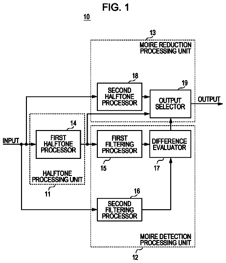
FIG. 1 is a conceptual module configuration diagram of an example of the configuration in accordance with this exemplary embodiment (image output apparatus);
FIG. 2 is a flowchart illustrating an example of processing in accordance with this exemplary embodiment (image output apparatus);
FIG. 3 is an explanatory diagram illustrating an example of a system configuration for implementing this exemplary embodiment;
FIGS. 4A and 4B are explanatory diagrams illustrating examples of an electronic document and an information image-combined document;
FIG. 5 is an explanatory diagram illustrating an example of the data structure of an entry order table;
FIG. 6 is an explanatory diagram illustrating an example of the data configuration of a document layout table;
FIGS. 7A to 7C are explanatory diagrams illustrating an example of an information image;
FIG. 8 is a conceptual module configuration diagram of an example of the configuration in accordance with this exemplary embodiment (image reading apparatus);
FIG. 9 is a flowchart illustrating an example of processing in accordance with this exemplary embodiment (image reading apparatus)
FIG. 10 is an explanatory diagram illustrating an example of the structure of a digital pen;
FIG. 11 is an explanatory diagram illustrating an example of the data structure of a stroke information table;
FIG. 12 is an explanatory diagram illustrating an example of the data structure of an entry order control table;
FIG. 13 is an explanatory diagram illustrating an example of the structure of another entry order control table;
FIG. 14 is a flowchart illustrating an example of processing in accordance with this exemplary embodiment (image reading apparatus);
FIG. 15 is an explanatory diagram illustrating an example of the structure of still another entry order control table;
FIG. 16 is an explanatory diagram illustrating an example of the structure of a further entry order control table;
FIG. 17 is an explanatory diagram illustrating an example of the structure of a still further entry order control table; and
FIG. 18 is a block diagram illustrating an example of the hardware configuration of a computer for implementing this exemplary embodiment.
Detailed description
Hereafter, with reference to the drawings, a description will be given of a preferred exemplary embodiment for implementing the invention.
FIG. 1 shows a conceptual module configuration diagram of an example of the configuration in accordance with this exemplary embodiment (image output apparatus).
It is noted that a module generally refers to a logically separable component, such as software (computer program) and hardware. Accordingly, the term "module" used in this exemplary embodiment means not only a module in a computer program but also a module in a hardware configuration. Therefore, the description of this exemplary embodiment also serves as the description of a computer program (a program for allowing a computer to execute respective procedures, a program for allowing a computer to function as respective units, and a program flow allowing a computer to implement respective functions), a system, and a method which serve to function as such modules. It should be noted, however, that although terms "store", "cause something to store", or equivalent terms are used for the convenience of explanation, these terms are to be construed as "to store something in a memory device" or "to control a memory device to store something" when the description of the exemplary embodiment is applied to the computer program. In actual application, however, one module may be configured by one program, plural modules may be configured by one program, and one module may conversely be configured by plural programs. Furthermore, plural modules may be executed by one computer, and one module may be executed by plural computers in a distributed or parallel environment. It is noted that other modules may be included in one module. Furthermore, the term "connection" is used herein not only for physical connection but also for logical connection (e.g., relationships for transmission and reception of data, instructions, and reference between data). The term "predetermined" means "being determined before object processing" and is used meaning not only "being determined before starting processing of the exemplary embodiment" but also "being determined depending upon the current or preceding situation or condition prior to the object processing even after starting processing of the exemplary embodiment".
Also, by a system or an apparatus is meant cases where plural computers, hardware, and apparatuses are configured by being connected to one another through a communication means such as a network (including communication connection in one-to-one correspondence), and also cases where the system or the apparatus is implemented by one computer, hardware, apparatus or the like. The term "apparatus" and the term "system" are used herein as substantially synonymous. The "system" does not include those which are merely social "mechanisms" (social systems) which are based on human agreements or arrangements.
In addition, in a case where plural processing is effected for processing by each module or within a module, object information is read from a storage device for each processing, and after the processing is effected, processing results are written into the storage device. Accordingly, as for reading from the storage device before processing and as for writing into the storage device after processing, there are cases where the description is omitted. It should be noted that, as storage devices used herein, a hard disk, a RAM (random access memory), an external storage medium, a storage device through a communication line, registers in a CPU (central processing unit), or the like may be included.
The image processing apparatus (image output apparatus) in accordance with this exemplary embodiment combines an information image with a document and outputs the combined result, and has an entry order acceptance module 110, a document layout acceptance module 120, a document acceptance module 130, an information image generation module 140, an information image combining module 150, and an output module 160, as shown in the example of FIG. 1.
It is noted that the information image refers to image codes which are systematically created for representing electronic data in a machine-readable form, and will be described later in a specific example with reference to FIG. 7.
The document acceptance module 130 is connected to the information image combining module 150. The document acceptance module 130 accepts a document to be combined with an information image, and delivers the document to the information image combining module 150. It is noted that the document may include text data or, in some cases, electronic data of a graphic, an image, or the like, or a combination thereof, which is subject to output (mainly printing), storage, editing, and retrieval, is replaceable by the document between systems or users, and includes data similar thereto. The "acceptance of a document" includes, for example, accepting an electronic document created by a word processing software, reading an image from a scanner, a camera, or the like, receiving an image from an external apparatus by a facsimile machine through a communication line, reading an electronic document stored in a hard disk (including such as one incorporated in the image processing apparatus and one connected thereto through a network), and the like. The image of the document may be a binary image or a multivalued image (including a color image). The image which is accepted may consist of one page or plural pages. The content of an image is one which has an entry field which is assumed to be handwritten by the user, and an inspection chart, an application form, and the like correspond thereto. It should be noted that the form of the entry field in general is a rectangular area enclosed by a line, but may not be limited thereto, and may be an area enclosed by brackets or the like. Those which are entered in the entry field may be characters, codes such as checks, graphics, and the like if they are written by a below-described digital pen.
The document layout acceptance module 120 is connected to the information image generation module 140. The document layout acceptance module 120 accepts information on the layout of the document accepted by the document acceptance module 130, and delivers the layout information to the information image generation module 140. The term "layout information" referred to herein includes at least information indicating the position and size of the entry field. Additionally, the layout information may also include information indicating the position and size of the document composition (title, paragraphs, drawings, tables, etc.) in outside the entry field.
The entry order acceptance module 110 is connected to the information image generation module 140. The entry order acceptance module 110 accepts the entry order in the entry fields within the document accepted by the document acceptance module 130, and delivers the entry order to the information image generation module 140.
By the "entry order" is meant the order of entry in entry fields with the below-described digital pen in a case where there are plural entry fields in that document. For example, that which corresponds to this is a case where, in an inspection chart serving as a document in a situation where product inspection is conducted at a factory, the order of inspection items is predetermined, check fields (entry fields) for indicating completion of the relevant inspection are provided for the respective inspection items, and a person in charge performs inspection in that order and enters check marks in the check fields each time one inspection is finished. Also, that which corresponds to this is a case where, in an application form having a preparer field, an approver field, and the like, entries by plural persons are required, and its order is predetermined. However, this is the case where entries are made by plural persons and are made by using one electronic pen. The "entry order" may indicate the order of entry on that page, or in a case where the document has plural pages, the "entry order" may indicate the order of entry in the plural pages.
In addition, the designation of the entry order may be received by using the user's mouse, keyboard, touch panel, or the like, or a predetermined entry order may be arranged to be received.
In addition, the entry order which is accepted by the entry order acceptance module 110 may further include an entry order in media with a document printed thereon. The "entry order in media" refers to an order of media into which entries are made with the digital pen in a case where there are plural media with a document printed thereon (paper mainly corresponds to such a medium, but the medium may be a plastic if it is printable, allows writing with the digital pen, and is a paper-like medium). As a specific example, the entry order may be page numbers of that document in a case where entries are made in the order of pages. Alternatively, in a case where entries are not made in the order of pages, the entry order may be an entry order in media which is prescribed independently of the page numbers.
The information image generation module 140 is connected to the entry order acceptance module 110, the document layout acceptance module 120, and the information image combining module 150. The information image generation module 140 generates an information image which is an image indicative of information, on the basis of positional information indicating a position within a document accepted by the document acceptance module 130 and the entry order accepted by the entry order acceptance module 110. The information image generation module 140 generates the information image which is combined in the entry field, by using layout information (specifically, information indicating the position and size of the entry field) accepted by the document layout acceptance module 120 as well as the entry order. The phrase "on the basis of" herein used means that information including at least the positional information and the entry order is embedded in the information image. Namely, it suffices if the positional information and the entry order can be read out when the information image is subjected to analysis. The phrase "positional information which is embedded in the information image" refers to information which allows handwriting with the digital pen to be reproduced in a case where the information image with the positional information embedded therein is read, and X-Y coordinates or the like in that document correspond thereto. Specifically, that which corresponds thereto is a set of X-Y coordinates in the document indicated by an area determined from the position and size of the entry field as the positional information.
In addition, the information image generation module 140 may be adapted to generate an information image on the basis of predetermined information in the case of a final entry field as the entry order in a document. The term "predetermined information" referred to herein is information which indicates that the field is a final entry field. It should be noted that the term "final" may refer to a final entry field in that page, or in a case where there are plural pages in the document, it may refer to a final entry field in that document. For example, "99" or the like corresponds thereto. Furthermore, respective information may be set as different "predetermined information." For example, an arrangement may be provided such that "99" indicates a final entry field in that page, while "999" indicates a final entry field in that document.
In addition, the information image generation module 140 may be adapted to further generate information image on the basis of the number of entry fields within a document. The number of entry fields within a document means a total number of entry fields. Alternatively, the number of entry fields within a document may be a total number of entry fields in that page, or in a case where the document has plural pages, it may be a total number of entry fields in that document. For example, as the entry order for embedment in information image, the entry order and the total number of entry fields may be combined. As a specific example, in a case where the entry order is 5 and the total number of entry fields is 6, "5/6" is used.
In addition, the information image generation module 140 further generates information image on the basis of document information indicating a document. As the document information, document ID (identification) corresponds thereto. It is noted that the document ID will be described in the description of the example of FIG. 3.
Patterns of information which are embedded in the information image generated by the information image generation module 140 include the following.
A first pattern includes: (A1) positional information (A2) entry order of entry fields
A second pattern includes: (B1) document ID (B2) positional information (B3) entry order of entry fields
A third pattern includes: (C1) document ID (C2) page ID (C3) positional information (C4) entry order of entry fields
A fourth pattern includes: (D1) document ID (D2) page ID (D3) positional information (D4) entry order of entry fields (D5) entry order of pages
Further, the entry order of entry fields of each pattern may include the total number of entry fields. Furthermore, the entry order of pages may include the total number of pages to be entered. It is to be noted that the entry order of pages in (D5) of the fourth pattern may be substituted by the page ID in (D2). However, to cope with a case where the order of entry does not correspond to the page order, the entry order of pages in (D5) is provided in addition to the page ID in (D2) as in the fourth pattern).
The information image combining module 150 is connected to the document acceptance module 130, the information image generation module 140, and the output module 160. The information image combining module 150 combines the information image, which is generated by the information image generation module 140, in the entry field within the document accepted by the document acceptance module 130.
The output module 160 is connected to the information image combining module 150. The output module 160 outputs a document with an information image combined therewith by the information image combining module 150. Falling under the category of the output of an image are printing by a printing apparatus such as a printer, transmitting an image by an image transmitting apparatus such as a facsimile machine, and the like. Also, the output module 160 may effect display on a display unit such as a display, writing an image to an image storage device such as an image database, storing in a storage medium such as a memory card, delivering to another information processing apparatus, and the like, but outputs a document to a medium such as paper so as to allow handwriting with the digital pen.
FIG. 2 is a flowchart illustrating an example of processing in accordance with this exemplary embodiment (image output apparatus).
In Step S202, the document acceptance module 130 accepts an object document. In Step S204, the document layout acceptance module 120 accepts the layout (at least the position and size of the entry field) of the object document.
In Step S206, the entry order acceptance module 110 accepts the entry order of entry fields within the object document.
In Step S208, the information image generation module 140 generates information image including the position of the entry field within the document and the entry order. In Step S210, the information image combining module 150 combines the information image in the entry field within the object document.
In Step S212, the output module 160 outputs the document with the information image combined therewith.
FIG. 3 is an explanatory diagram illustrating an example of a system configuration for implementing this exemplary embodiment. In the illustrated example, the system includes a document preparing information processor 310, a document DB 320, an information image generating image processor 330, a digital pen 350, and a rewriting information processor 360. However, to allow the digital pen 350 to issue an alarm in a case where entries are made in a different order, it suffices if the information image generating image processor 330 and the digital pen 350 are provided.
This system performs the following processing. An information image containing positional information (coordinate information) is superimposed on an electronic document and is printed by the information image generating image processor 330. As the electronic document with the information image superimposed thereon is read out by the digital pen 350 with a compact camera incorporated therein, handwriting information is accumulated in the digital pen 350 as stroke information. If the digital pen 350 is connected to the rewriting information processor 360 such as a PC by means of a USB or the like, a stroke information extraction module 362 and a rewrite module 364 in the rewriting information processor 360 extract the stroke information from the digital pen 350, specify the original electronic document from the document ID, and rewrite the stroke information to that electronic document. In addition, the digital pen 350 may transmit the stroke information to the rewiring information processor 360 through wireless communication.
The document preparing information processor 310 has a document preparation application 312 and an entry order designation module 314, and is connected to the document DB 320 and the information image generating image processor 330.
The document preparation application 312 is an application program which prepares an electronic document and prints an information image-combined document 340 subject to editing by handwriting.
The entry order designation module 314 designates the order of entry fields. For example, the entry order designation module 314 delivers an entry order table 500 to the information image generating image processor 330. Further, an entry order acceptance module 11a in the information image generating image processor 330 accepts the entry order table 500. FIG. 5 is an explanatory diagram illustrating an example of the data structure of the entry order table 500. The entry order table 500 has an entry field ID field 510 and an entry order field 520. The entry field ID field 510 is for storing an entry field ID which is information for uniquely identifying the entry field in the system exemplified in FIG. 3, and the entry order field 520 is for storing the entry order in that document or that page.
The document preparation application 312, at the time of document printing, designates the name of a device for printing (printer name, name of the information image generating image processor 330), generates a document image, delivers it to the information image generating image processor 330 together with the document ID and the entry order designated by the entry order designation module 314, and gives a printing instruction thereto. Order information is embedded, for each entry field, in the printed information image. Further, the prepared electronic document is stored in the document DB 320. In addition, information (e.g., a document layout table 600) concerning the layout of entry fields of the object document is also delivered to the information image generating image processor 330. Further, the document layout acceptance module 120 in the information image generating image processor 330 accepts information concerning the layout. FIG. 6 is an explanatory diagram illustrating an example of the data configuration of the document layout table 600. The document layout table 600 has an entry field ID field 610, a position field 620, a height field 630, and a width field. The entry field ID field 610 is for storing the entry field ID. The position field 620 is for storing, for example, an upper left position of that entry field. The height field 630 is for storing the height of that entry field. The width field 640 is for storing the width of that entry field.
The document DB 320 is connected to the document preparing information processor 310 and the rewriting information processor 360. The document DB 320 stores the electronic document prepared by the document preparation application 312. Further, the writing information obtained by the digital pen 350 is combined with the stored electronic document by the rewrite module 364.
The information image generating image processor 330 is connected to the document preparing information processor 310, is the image processing apparatus (image output apparatus) shown in the example of FIG. 1, prints the electronic document prepared by the document preparing information processor 310, and outputs an information image-combined document 340 with the information image combined therewith. The information image-combined document 340 is a paper document generated by printing an electronic document, and is a paper document with the positional information superimposed thereon as the information image. It should be noted that the document ID may be embedded in the information image.
Here, with reference to FIGS. 4A and 4B, a description will be given of examples of an electronic document 410 and the information image-combined document 340.
The electronic document 410 exemplified in FIG. 4A is a document prepared by the document preparation application 312 and is stored in the document DB 320. For example, it is assumed that there are six entry fields, and that the order of an entry field 411, an entry field 412, an entry field 413, an entry field 414, an entry field 415, and an entry field 416 is designated as the entry order. In particular, the entry field 416 is a final entry field in this document or page, and if an entry is made in this entry field 416, it is possible to proceed to writing in another document or another page.
The information image-combined document 340 exemplified in FIG. 4B is a paper document printed by the information image generating image processor 330, and writing is effected by the operation of the digital pen 350 by the user. The information image, in which positional information and the respective entry order are embedded, is combined in an entry field 421, an entry field 422, an entry field 423, an entry field 424, an entry field 425, and an entry field 426 of the information image-combined document 340. Further, an information image with the positional information embedded therein is combined in a background 429. It should be noted that the information image may not be combined in the background 429.
FIGS. 7A to 7C are explanatory diagrams illustrating an example of the information image.
This example, developed at the Palo Alto Research Center of the Xerox Corporation, is a two-dimensional code pattern image which using a glyph code as a code symbol, i.e., an information image, for expressing data by diagonals having differing angles.
In this example, a unit area 700 is a square area consisting of 8 symbols.times.8 symbols. The value of each symbol is expressed by diagonal patterns, as shown in FIGS. 7B and 7C. In this example, the symbol value of 0 is expressed by a diagonal slanting downward to the right (pattern 0 in the example of FIG. 7B) forming a counterclockwise angle of 45.degree. with respect to a vertical line, while the symbol value of 1 is expressed by a diagonal slanting upward to the right (pattern 1 in the example of FIG. 7C) forming a clockwise angle of 45.degree. with respect to the vertical line.
In this unit area 700, a position code image 702 is a square image consisting of 6 symbols.times.6 symbols at an upper left corner of the unit area 700, and an identification code image 704 is an image of an inverse L-shaped region remaining after subtracting the square with 6.times.6 symbols from the unit area 700.
In addition, in this example, a column and a row of synchronizing codes 706 are provided in vertical and horizontal directions along the outer periphery of the unit area 700. In this example, the synchronizing codes 706 are successive diagonal symbols slanting upward to the right ("1"), and the size and arrangement pitch of the symbols are the same as the symbol size and pitch in the unit area 700. The synchronizing codes 706 are provided vertically and horizontally at equal intervals, and each unit area 700 is provided in a square region encompassed by these synchronizing codes 706. The synchronizing codes 706 indicate a demarcation of each unit area 700. Namely, in the apparatus which scans the two-dimensional code pattern image, if it detects a row and a column of successive diagonal symbols slanting upward to the right, it is possible to recognize that the interior of the mesh grid formed by the row and the column is the unit area 700, and that the 6.times.6 symbols at the upper left corner of that unit area 700 constitute the position code image 702.
It should be noted that insofar as the synchronizing codes 706 are able to specify the location of the unit area 700 or the position code image 702, the synchronizing codes 706 may not be such as those exemplified in FIG. 7A. For example, those in which symbols of a specific shape different from those of the diagonal symbols are arranged at the four corners of the unit area 700 may be used as the synchronizing codes 706. In the example of FIG. 7A, a row and a column having a width corresponding to that of one symbol are used for the synchronizing codes 706. However, if the marks making up the synchronizing codes 706 are sufficiently small, the unit areas 700 may be arranged in two dimensions without gaps and the marks may be positioned in the margins of the adjacent unit areas 700.
In the example of FIG. 7A, one position code image 702 stores a total of 36 symbols, namely, 36 bits of data. Among the 36 bits, 18 bits can be used to encode the x coordinate and 18 bits can be used to encode the y coordinate. If all of both 18-bit coordinates are used to encode the position, 2 to 18 possible positions (approximately 260,000 positions) can be encoded. If each diagonal pattern is formed from 8.times.8 pixels as shown in FIGS. 7B and 7C and printed at 600 dpi (dots per inch), a length in the vertical or horizontal direction of one dot at 600 dpi is 0.0423 mm so that for both the vertical and horizontal directions the height and width of the two-dimensional code (including the synchronizing codes 706) in FIG. 7A is approximately 3 mm (=8 pixels/symbol.times.9 symbols.times.0.0423 mm). If 260,000 possible positions are encoded at 3 mm intervals, a length of approximately 786 m can be encoded. If the reading accuracy is high, all 18 bits can be used to encode the position. However, in cases where read errors present a problem, it is preferable to include redundancy bits for error detection or error correction. Increasing the proportion of redundancy bits among the 18 bits increases the error detection or error correction capability but decreases the range of positions which can be expressed. Furthermore, in the example of FIG. 7A, the identification code image 704 is positioned in a 2 bit.times.8 bit rectangular region or a 2 bit.times.6 bit rectangular region so that a total of 28 bits of identification information can be stored. If 28 bits are used for identification information and the like, approximately 270 million possible (2 to 28) types of identification information and the like can be expressed. However, several of the 28 bits may be used as redundancy bits for error detection or error correction to thereby make it possible to cope with read errors. It is noted that, in this exemplary embodiment, the "identification information and the like" include at least the entry order, and may additionally include the document ID, the page ID, and the like. For example, a sheet identification number or the like for uniquely identifying a sheet may be included.
The identification code images 704 in the unit areas 700 which are printed in entry fields on one sheet are identical. Needless to say, since the positional information expressed by the position code image 702 in the unit area 700 is the information indicating the position in that sheet, the position code images 702 in the respective unit areas 700 are different.
In the above-described example, one bit of data is expressed by one symbol as two diagonal patterns, which are mutually different by 90 degrees, are used as symbols. However, this is only one example. For example, if vertical line and horizontal line patterns are added to the symbols, two bits of information can be expressed by one symbol. In this manner, the number of bits which can be expressed by one symbol can be increased by increasing the number of types of angles for the diagonal patterns of one symbol. Additionally, information images other than glyph codes may be used.
As the user writes down on the information image-combined document 340, the digital pen 350 (also called a pen with a scanner and an electronic pen) reads out an information image, extracts handwriting as stroke information, and transmits it to the rewriting information processor 360. Further, the digital pen 350 detects whether the entry into the entry fields is being carried out according to the entry order and, if not, the digital pen 350 issues an alarm. The configuration of the digital pen 350 and its processing contents will be described later with reference to FIG. 8 and the drawings that follow. It should be noted that the "stroke information" referred to herein is information which is expressed as a series of coordinates acquired by effecting writing into the information image-combined document 340 with the digital pen 350.
The rewriting information processor 360 has the stroke information extraction module 362 and rewrite module 364, and is connected to the document DB 320 and the digital pen 350.
The stroke information extraction module 362 has the function of acquiring from the digital pen 350 the stroke information of handwriting written to the information image-combined document 340. The stroke information includes the document ID, the page number, stroke strings (strings of positional information), and the like of the information image-combined document 340 into which writing has been made.
The "document ID" is information for uniquely identifying a document in the system exemplified in FIG. 3, and the electronic document and a paper document with that electronic document printed thereon have the same document ID. The document ID is required to specify the original electronic document by identifying the paper document subjected to writing by hand. It should be noted that, the document ID is not an essential requirement to allow an alarm to be issued when entries in a different order are made with the digital pen 350. Furthermore, another form may be adopted insofar as the relationship between the electronic document and the paper document can be specified.
The rewrite module 364 is an application program for rewriting to an original electronic document the stroke information which has been written into the information image-combined document 340 with the digital pen 350. The rewrite module 364 performs processing in which the stroke information received from the stroke information extraction module 362 is reflected as stroke information on the electronic document on the basis of information on the document ID and the page ID.
FIG. 8 is a conceptual module configuration diagram of an example of the configuration in accordance with this exemplary embodiment (image reading apparatus). The image processing apparatus (image reading apparatus) in accordance with this exemplary embodiment reads a document with an information image combined therewith, and has a reading module 810, an information image analysis module 820, an entry order control module 830, an alarm module 840, a stroke information generation module 850, and a transmission module 860, as shown in the example of FIG. 8. These modules are accommodated in the digital pen 350 exemplified in FIG. 3.
The reading module 810 is connected to the information image analysis module 820. The reading module 810 is connected to the information image analysis module 820. The reading module 810 reads out the information image, outputted on a medium such as paper, for extracting the position of writing with a writing instrument. The "medium such as paper" herein refers to a document which has combined therewith an information image, i.e., an image representing information generated on the basis of the entry order in the entry fields within the document as well as the positional information indicating the position in that document. In the above-described example, the reading module 810 reads out an image of the writing position in the information image-combined document 340. An image reading module 1052 in the example of FIG. 10 referred to hereinafter corresponds thereto.
Further, the information image which is read out by the reading module 810 may further contain the number of entry fields in the document.
Further, the information image which is read out by the reading module 810 may further contain the entry order in media with a document printed thereon.
Further, the information image which is read out by the reading module 810 may further contain the document information indicating a document.
The information image analysis module 820 has a positional information extraction module 822, an entry order extraction module 824, and a document-related information extraction module 826, and is connected to the reading module 810, the entry order control module 830, and the stroke information generation module 850.
The positional information extraction module 822 analyzes the information image which has been read out by the reading module 810, and extracts positional information. Namely, the positional information extraction module 822 extracts information on the written position, and is thereby able to generate stroke information serving as writing information.
The entry order extraction module 824 analyzes the information image which has been read out by the reading module 810, and extracts the entry order from the identification information or the like.
Further, the entry order extraction module 824 may be adapted to further extract the number of entry fields in the document in a case where the number of entry fields in the document is included in the information image which is read out by the reading module 810.
Furthermore, the entry order extraction module 824 may further extract the entry order in media in a case where an entry order in the medium with a document printed thereon is included in the information image.
The description continues in the full USPTO document.
 Lapsed, fee not paid7 drawings