Technical field
This application relates to mass spectrometry instruments and analysis.
Background
The role of aerosols in atmospheric chemistry has recently become of great interest, because relatively little is known regarding the reactivity and transport of environmental aerosols. The catalytic effect of aerosol particles in heterogeneous (gas-particle) reactions occurring in the atmosphere is known to depend on both the particle's surface area and the particle's chemical composition.
Aerosol characterization also can be important in the medical and industrial fields. Great efforts have been made to study the effects of particles in biological systems, particularly on the human lungs and cardiovascular system. Although carcinogenicity and toxicity both depend on chemical composition, the chemical will have little influence on the body unless it is in some way retained. Particles ranging from ultrafine (<100 nm) up to 10 microns are of interest because they are the most likely to serve as carriers of toxic chemicals and to be deposited in some part of the human body (i.e. lungs, bloodstream, liver, heart, brain) for significant time durations. Due to health concerns, industries that require employees to operate in dust-laden environments, e.g., mines, also are interested in aerosol characterization. Further, may need to determine the contents of the air to maintain clean semiconductor devices.
In addition, the ATOFMS can be designed to identify various biological particles and sources including single cells and microorganisms. For example, specific cell (e.g., cancer cell) can be identified among a tissue sample to identify a target of pharmacological agents and to confirm that enough of the cancer cells were removed during surgery (pathology application).
Mass spectrometry is a technique for analyzing many types of environmental and biological samples, including aerosols. When combined with some means to determine particle size, mass spectrometry can provide means for determining both the size and chemical composition of particles in a polydisperse sample. Mass spectrometers generally include the following four basic steps as part of their analysis: 1) sample introduction; 2) sample volatilization and ionization; 3) mass separation; and 4) ion detection. Numerous routines can be used to perform each of these steps, although not all may be compatible with aerosol characterization. Sample introduction into a mass spectrometer for aerosol characterization can be performed in one of following two ways:
placing the sample on a surface, or
forming a particle beam by free jet expansion into a vacuum. Sample volatilization and ionization in the case of aerosol mass spectrometric analysis can utilize any of numerous suitable techniques, including, for example, laser desorption/ionization. Mass separation also can be accomplished using any of multiple techniques, including, for example a time-of-flight mass analyzer. Finally, ion detection can be accomplished using, for example, microchannel plate detectors.
Summary
In one aspect, a mass spectrometry apparatus includes an ionization laser to produce a deionization laser beam. The apparatus also includes a particle beam path that receives aerosol particles and intersects the ionization laser beam at a location where aerosol particles are desorbed and ionized by the laser beam. The apparatus also includes an ion extractor located at or near the ionization location to separate positive ions and negative ions desorbed from the aerosol particles and to direct the positive ions along a first direction of an ion path and the negative ions along a second, opposite direction of the ion path. The apparatus also includes a first reflectron located at a first side of the ion extractor, on the ion path, to reflect the positive ions along a first reflection path that deviates from the ion path, A second reflectron is located at a second, opposite side of the ion extractor, on the ion path, to reflect the negative ions along a second reflection path that deviates from the ion path and that is located on a side of the ion path that is opposite the first reflection path. In addition, a first ion detector is located on the first reflection path, to receive and detect the positive ions reflected from the first reflectron. Further, a second ion detector is located on the second reflection path to receive and detect the negative ions reflected from the second reflectron. The ion path connects the first reflectron, the ion extractor, and the second reflectron. The first reflection path connects the first reflectron and the first ion detector. The second reflection path connects the second reflectron and the second ion detector form a Z-shaped path.
Implementations can optionally include one or more of the following features. An inlet can be provided for receiving particles to be sampled. An aerodynamic lens can be connected to the inlet and designed to detect the received particles. A sizing region can be connected to the inlet and designed to size the received particles. An ionization region can be connected to the sizing region and designed to ionize the sized particles. The ionization region includes the ion extractor, the first and second reflectrons, and the first and second ion detectors. In addition, the sizing region can be located along the particle beam path, and the sizing region includes a first scattering laser and a second scattering laser. The first scattering laser can be located at a higher plane than the second scattering laser and positioned orthogonal to the second scattering laser. The aerodynamic lens can be designed to transmit and focus particles having sizes in the range of 70-3000 nanometers. An adjustable dome-top interface can be connected to the aerodynamic lens system, with the dome-top interface designed to enable spherical alignment of the aerodynamic lens system with center of light scattering and ion source regions of the mass spectrometer. In addition, the mass spectrometer apparatus can include a neutralizer located along the particle beam path to enable transmission and detection of particles having sizes Da<200 nm by reducing lateral deflection caused by high electrostatic gradients in the desorption/ionization or ion source region. Further, the Z-shaped path can be designed to increase ion transmission and mass range. Also, the ionization region can be designed to have a length shorter than a length of the Z-shaped path.
In addition, implementations can optionally include one or more of the following features. The inlet, the aerodynamic lens, the sizing region, and the ionization region can be designed to fit inside a small platform including at least one of an aircraft, van, truck, helicopter, and unmanned aerial vehicle. The mass spectrometer apparatus can include a signal processor to process detector output signals of the first and the second ion detectors and to determine chemical compositions of the positive and negative ions associated with each sized, desorbed, and ionized aerosol particle. The mass spectrometer apparatus can also include a first digitalization board to acquire detector output signal from the first ion detector; and a second digitalization board to acquire detector output signal from the second ion detector. Each board can include two input channels, one to acquire an unattenuated ion detector signal and the other to acquire an attenuated ion detector signal. One or more tapered flanges can be used to align and connect components of the apparatus. Examples of tapered flanges 283 are shown in FIG. 2E. Further an adjustable laser mount can be provided to adjustably attach at least the first and second scattering laser to the sizing region, the adjustable laser mount includes at least the following components. The laser mount can include a rotating unit attached to an exterior wall of the sizing region to providing rotation of the laser mount along axis of laser beam. The laser mount can also include an alignment unit attached to the rotating unit to provide an indication a centered laser beam. The laser mount can also include an adjustable laser housing attached to the alignment unit. The adjustable laser housing can include a first adjustment unit attached to a wall of the adjustable laser housing to provide adjustments of the scattering lasers in horizontal direction. The adjustable laser housing can also include a second adjustment unit attached to the first adjustment unit to provide adjustments of the scattering lasers in vertical direction. The first adjustment unit can include two or more adjustment units of different thickness to provide adjustments in horizontal plane. Further, the laser mount is adjustable to sweep across a horizontal plane.
In another aspect, performing real-time source apportionment includes receiving aerosol particles through a particle beam path. The received aerosol particles are sized by detecting light scattered from the received particles. The sized particles are desorbed and ionized. The positive ions and negative ions desorbed from the ionized aerosol particles are separated. The separated positive ions are directed along a first direction of an ion path, and the negative ions are directed along a second, opposite direction of the ion path.
Implementations can optionally include one or more of the following features. The positive ions can be reflected along a first reflection path that deviates from the ion path. The negative ions can be deflected along a second reflection path that deviates from the ion path and that is located on a side of the ion path that is opposite the first reflection path. The reflected positive ions and the reflected negative ions can be separately detected. The first and second directions of the ion path, and the first and second reflectron paths can form a Z-shaped path. In addition, ionization of the particle can include firing a ionization laser at the sized particles. Further, sizing the received particles can include using a first scattering laser to scatter light off the received particles, and using at least a photo multiplier tube to detect the scattered light. Based on the detected scattered light, a timing circuit count-up process can be started. Also, a second scattering laser can be used to scatter light off the received particles for a second time. The second scattered light can be detected using another photo multiplier tube, and based on the second detection, the timing circuit count-up can be stopped and a timing circuit count-down process can be started. An aerodynamic lens can be used to detect the received particles having sizes in the range of 80-2000 nanometers. Further, particles having sizes Da<200 nm can be transmitted and detected by reducing lateral deflection caused by high electrostatic gradients. The Z-shaped path can be formed to increase ion transmission and mass range. Further, signals from the detected positive ions and negative ions can be processed to determine chemical compositions of the positive and negative ions associated with each ionized aerosol particle. The signal from the detected positive ions and the signal from detected negative ions can be acquired. The signals from the positive ions and the negative ions can be acquired separately.
The subject matter as described in this specification potentially can provide one or more of the following advantages. An aircraft (A)-ATOFMS can be designed to provide aircraft-based measurements. Such A-ATOFMS is capable of data acquisition rate that is up to three times faster than is possible with conventional laboratory and transportable ATOFMS. In addition, the A-ATOFMS can enable improved ion transmission and mass resolution, while being lighter, smaller, and consuming less power than conventional laboratory and transportable ATOFMS. By reducing the foot-print (i.e., physical size) and power consumption while adding shock absorption components, the A-ATOFMS can be used in light aircraft and any other mobile platforms. The improved ion transmission can enable the first detection of ions out to 10,000 m/z, which can be important for detecting biological and oligomeric aerosols. Further, an increased particle size range of 70-3000 nm can enable the investigation of the physical and chemical properties of a wide range of atmospherically-relevant aerosols.
Other features and advantages of the present invention should be apparent from the following detailed description, taken in conjunction with the accompanying drawings, which illustrate, by way of example, the principles of the invention.
The subject matter described in this specification can be implemented as a method or as a system or using computer program products, tangibly embodied in information carriers, such as a CD-ROM, a DVD-ROM, a semiconductor memory, and a hard disk. Such computer program products may cause a data processing apparatus to conduct one or more operations described in this specification.
In addition, the subject matter described in this specification can also be implemented as a system including a processor and a memory coupled to the processor. The memory may encode one or more programs that cause the processor to perform one or more of the method acts described in this specification. Further the subject matter described in this specification can be implemented using various data processing machines.
Brief description of the drawings
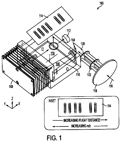
FIG. 1 illustrates a system for performing on-the-fly (real-time) source apportionment.
FIGS. 2A, 2B illustrate an example ATOFMS designed to have a small foot-print and increased data acquisition capabilities.
FIG. 2C shows a mass spectrometer of an ATOFMS implemented as the Z-TOF having a compact dual polarity grid-less reflectron design.
FIGS. 2D illustrates a folded path geometry of a Z-TOF mass spectrometer.
FIG. 2E illustrates the use of tapered flanges to connect various components of the ATOFMS.
FIG. 3 is a table showing improvements provided by a Z-configuration design over a linear-configuration design.
FIG. 4 is a block diagram showing an example mount design for mounting a scattering laser.
FIGS. 5A and 5B are block diagrams of a Data Acquisition and Control Software.
FIGS. 6A, 6B, 6C are process flow diagrams of an example process for sampling particles.
FIG. 7 is a screenshot of the software that provides on a single screen displaying various real-time information for sized particles, hit particles, and instrument status.
FIG. 8 shows various particle size transmission curves through the aerodynamic lens.
FIG. 9 shows a size calibration curve.
FIG. 10 illustrates the higher mass/charge range as an example of the performance of the new A-ATOFMS.
FIG. 11 is a block diagram of a system for operating an example ATOFMS device operating autonomously at a remote location.
Like reference symbols and designations in the various drawings indicate like elements.
Detailed description
FIG. 1 illustrates a system 100 for performing on-the-fly (on-line or real-time) source apportionment. The system 100 includes an aerosol time-of-flight mass spectrometer (ATOFMS) 110 and system control hardware 120 executing data acquisition and control (DAC) software 130. The system control hardware 120 interfaces with the ATOFMS 110 using a data communication link 140 to control operation of the ATOFMS and receive data from the ATOFMS 110. Data acquisition and control of the ATOFMS 110 is performed by the DAC software 120 executing on the system control hardware 120.
The system 100 is controlled by the system control hardware 120 that can include various data processing devices. For example, the system control hardware 120 can be implemented as a rack mounted PC with an Intel P4 3.2 GHz processor, 2 GB RAM, and Microsoft Windows XP Pro SP 2 operating system. Mass spectral data from the ATOFMS 110 is digitized using two Acqiris 2 channel fast data acquisition boards with a 1 GHz sampling rate for wide dynamic range ion signal acquisition (may want to add this description). Files that represent at least the digitized data are saved onto a removable 80 GB 7200 rpm IDE hard drive (Western Digital, Lake Forest, Calif.). The system control hardware 120 can include other computer PCI boards that enables control of the ATOFMS 110 and data acquisition. For example, a 96 pin digital I/O board (model DIO96, National Instruments Corp., Austin, Tex.) can be provided to retrieve a timing circuit counter number and send reset command. In addition, a 16 channel RS-232 board (model 16 port serial breakout box, National Instruments Corp., Austin, Tex.) can be used to monitor and control various component of the ATOFMS 110 such as the pumps, pressures, and laser power meter (model Molectron EPM1000, Coherent, Inc, Santa Clara, Calif.).
The system control system 120 interfaces with the ATOFMS 110 using various wired connections as described above. In addition, other wired and wireless connections can be implemented. For example, the wired data connections can include various universal serial bus (USB) connections, serial transmission mechanisms, parallel transmission mechanisms, etc. Wireless data connections can include wireless fidelity (WiFI), FireWire, WiMax, etc. In some implementations, the system control system 120 is located at a remote location and controls the ATOFMS and acquires data from the ATOFMS over a network connection such as local area network (LAN), wide area network (WAN) and the internet.
Aerosol time-of-flight mass spectrometers can be used to measure the precise size and chemical composition of individual aerosol particles, in real time. Such systems can be used to characterize a wide range of aerosol particles, including secondhand tobacco smoke, suspended soil dust, sea salt, aerosols, and a variety of combustion particles. Such systems also can be used to monitor the evolution of individual aerosol particles in the atmosphere over time. ATOFMS systems that are configured as portable instruments are suitable for use in studying the direct effect of aerosols on visibility, pollution levels, and the global radiation balance. In addition, the ATOFMS can be designed to identify various biological particles and sources including single cells and microorganisms. For example, specific cell (e.g., cancer cell) can be identified among a tissue sample to identify a target of pharmacological agents and to confirm that enough of the cancer cells were removed during surgery (pathology application).
FIGS. 2A, 2B, 2C, 2D illustrate an example ATOFMS 200 designed to have a small foot-print and increased data acquisition capabilities. The ATOFMS 200 is constructed using various components. For example, the example
ATOFMS 200 as illustrated includes a critical orifice 205, an aerodynamic lens system 210, multiple turbomolecular pumps (212, 214, 216, 218), a dome-top interface 220, an exit nozzle 225, a skimmer 230, one or more photomultiplier tubes (PMTS) 235, a split-flow turbo-molecular pump 240, two light scattering lasers 245, 246, a desorption/ionization laser 250, and a mass spectrometer 255. FIGS. 2A, 2B are illustrative of the example ATOFMS 200 only and the total number of each components used can vary depending on the application.
The example ATOFMS 200 can be implemented as a combination of various systems including an inlet system 260, a light scattering system 270, a pump system 280, and a mass spectrometer system 290. Each of these systems 260, 270, 280 and 290 includes one or more of the ATOFMS components described above and provides various functionalities.
The inlet system 260 is designed to provide a reduced volume when compared to other conventional ATOFMS. For example, the inlet system 260 can provide a volume that is reduced by 3/4 compared to the previous ultrafine (UF)-ATOFMS25. In addition, the inlet system features an adjustable dome top interface 220 designed to align the particle beam, enable symmetric pumping, and enable testing of a variable number (1-4) of turbo molecular pumps. The dome top interface 220 includes two concentric hemispheres mating with hardened aluminum surfaces. Threaded adjusters can be provided to vary the dome position, which is monitored (e.g., using analog dial gauges). Threaded adjusters enables accurate alignment and quick verification that alignment has not changed.
The inlet system 260 also includes the aerodynamic lens system 210. A variable number of turbo molecular pumps can be tested to determine their effect on the aerodynamic lens performance and to experimentally determine the minimum number of pumps required to reduce the weight and power consumption. Small adjustments (.+-.0.005 inches in the x-y plane) of the dome-top interface 220 alignment may not result in any measurable effect on the scattering rate. Because slight adjustments of the dome-top interface 220 alignment may be needed to align the particle beam, in some implementations, a fixed dome-top interface 220 is used to minimize weight and complexity while rigidly maintaining the alignment in a harsh vibrating operating environment.
The light scattering system 270 can be designed to enable easy alignment of the scattering laser 245 in both horizontal (X), perpendicular to particle beam, and vertical (Y), parallel to the particle beam, directions. The light scattering system 270 uses a mounting mechanism that enables vertical (Y) alignment with shims, so the vertical alignment is set once with a centering jig prior to mounting the scattering laser 245 to the instrument and needs no further adjustment. Horizontal (X) adjustment is easy and repeatable, using nested cylinder joints and a dial indicator gauge. This is an improved design over other systems such as those that utilize a ball and socket joint that enables swift alignment, but is difficult to use in practice as both the X and Y directions are free to move about at the same time. The scattering laser used includes a 532 nm scattering laser manufactured by JDS Uniphase. The JDS Uniphase laser provides RS-232-C controllability and improved beam characteristics.
The pumping system 280 is implemented to provide various pumping configurations and operating pressures. The pumping system 280 includes various pumps that operate over multiple pumped sections. For example, three differentially pumped sections including
the aerodynamic lens system 210,
a sizing (scattering) region 272 (includes 2 scat lasers and 2 PMT's for light detection), and
the mass spectrometer 255. The pumping system 280 uses smaller pumps to reduce cost, power draw, and weight. For example, the pumping system 280 includes a much smaller and lighter inlet with three 70 L/s turbo-molecular vacuum pumps 215 (model Turbo-V 70LP, Varian Vacuum Technologies, Torino, Italy) on the exit of the aerodynamic lens system 210 and one 250 L/s split-flow turbo-molecular vacuum pump 240 (model Turbo-V 301 SF Navigator, Varian Vacuum Technologies, Torino, Italy) on the mass spectrometer 255. The pumping system 280 can optionally include an optional 70 L/s turbo-molecular vacuum pump (not shown) on the sizing region 272. A secondary inlet (11 L/s) on the split-flow turbo-molecular vacuum pump (TV-301SF) backs the four 70 L/s pumps. One or more turbo pump controllers (not shown) interfaces with the system control hardware 120 to enable control and monitoring of the pumps 212, 214, 216, 218 and 245. The split-flow turbo-molecular vacuum pump 245 is backed by two diaphragm rough pumps (not shown): a UN726.1.2 ANI parallel pump and a UN726.3 ANI two stage (KNF NEUBERGER, INC., Trenton, N.J.) pump. The two heads on the first rough pump are in parallel (38 L/min), and the two heads on the second are in series (20 L/min).
Typical operating pressures are .about.1.7 Torr for the relaxation region 211 (model 626A Baratron Capacitance Manometer, MKS Instruments, Wilmington, Mass.), .about.6.times.10-3 Torr after the aerodynamic lens system 210 (model 345 HPS.RTM. Pirani sensor, MKS Instruments, Wilmington, Mass.), .about.3.times.10-4 Torr in the aerodynamic sizing region 272 (same as the scattering or sizing region described above) (model I-Mag 423, MKS Instruments, Wilmington, Mass.), .about.7.times.10-7 Torr in the mass spectrometer 255 (model I-Mag 423, MKS Instruments, Wilmington, Mass.), and .about.8.5 Torr in the fore line (not shown) (model 345 HPS.RTM. Pirani sensor, MKS Instruments, Wilmington, Mass.) between the TV-301 and first rough pump. The aerodynamic sizing region 272 is separated from the mass spectrometer 255 by a ball valve which can be closed to isolate the mass spectrometer 255 and keep the ion detectors under vacuum while the remainder of the instrument is serviced.
The mass spectrometer 255 can be implemented as a dual polarity Z configuration time-of-flight (Z-TOF) mass spectrometer. The dimensions of the Z-TOF mass spectrometer 255 are designed to be substantially smaller than other conventional mass spectrometers. For example, the Z-TOF mass spectrometer 255 can be designed to have a length and a volume that are 31% and 43% of the conventional ATOFMS coaxial mass spectrometer. The example A-ATOFMS mass spectrometer dimensions are 49.times.29.times.11.3 cm (L.times.W.times.H) compared to 159.times.15.times.15.5 cm for the transportable ATOFMS. The shorter length results in a much smaller package and enables the A-ATOFMS to be placed in a light aircraft, for example.
FIG. 2C shows the mass spectrometer 255 implemented as the Z-TOF having a compact dual polarity gridless reflectron design. The mass spectrometer performance is improved by using detailed ion simulations (SIMION 3D 7.0 developed by David Dahl, Idaho National Lab, Scoville, Id.) and geometry optimization. The design of the Z-TOF includes the following assemblies:
a single ion source region 253,
2 flight tubes--(they run between the detectors and the reflectrons--i.e. between 257a and 259A is one flight tube and between 257b and 259b is the other flight tube), 2 reflectrons 259a and 259b, and 2 detectors 257a and 257b. The modular design of the Z-TOF enables easy assembly and simplifies maintenance. The negative/positive ions are extracted with plates separated by 6.0 mm at +/- 3 kV, accelerated to 8-10 kV, spatially focused with an electrostatic Einzel lens at +/-2 kV before entering a field free region at +/-8 to 10 kV, and then refocused in a reflectron 259a, 259b onto an ion detector 257a, 257b. The ion flight path is 5.9 cm long and typical flight times are .about.7 .mu.s for m/z 100 Daltons. The desorption/ionization (DI) laser 250 light is focused with a lens (f=75 mm), enters the TOF mass spectrometer 255 through a fused silica window, passes through two 5.0 mm apertures in the flight tube and enters the source region before exiting through two similar apertures in the opposite flight tube and window in the Z-TOF mass spectrometer 255.
The LDI laser power measured at the exit of the Z-TOF mass spectrometer 255 is typically .about.1 mJ from the custom Big Sky (Montana) 50 Hz laser. The voltages on the Z-TOF mass spectrometer 255 are computer controlled and monitored by a custom high voltage supply (Tofwerk AG, Thun, Switzerland). A custom software safely ramps the high voltages, and a hardware pressure interlock protects the detectors 257a, 257b against damage due to sudden pressure increases. The bipolar detectors 257a, 257b use a MCP, scintillator, and photomultiplier tube and hence optically decouple the signal from high voltage, thereby additionally providing protection from damage to the expensive and sensitive DA boards caused by any potential arcing in the Z-TOF mass spectrometer 255.
FIGS. 2D illustrates a folded path geometry of the Z-TOF mass spectrometer designed to minimize the size of the mass spectrometer's 255 chamber (or housing) 256 and to improve the ion detection performance. The folded path geometry provides a path for positive ions 262 (i.e., first flight tube) in an opposite direction to a path for negative ions 264 (second flight tube) and forms a Z-shaped (or S-shaped) geometry. Positive and negative ion reflectrons 259a, 259b are placed away from, and at opposite sides of, an ion extractor 258. The two reflectrons 259a, 259b are each oriented to angularly reflect impinging ions (positive and negatively charged) received from the ion extractor 258 along a reflection path 262, 264 toward a respective ion detector 257a, 257b located near the opposite end of the mass spectrometer chamber 256. This design creates a folded Z-configuration path for the positive and negative ions, which lengthens the effective ion path length for a given chamber dimension (i.e., the ion path is longer than the length of the chamber). This Z-configuration thereby increases the time spread for ions of different mass-to-charge ratios to reach the ion detector 257a, 257b. This is an improvement over the conventional co-axial design that sends the ions down and back in the same flight tube. The conventional co-axial design does not take advantage of the fact that other polarity lengths (and widen it slightly) can be used for ion detection Conventional co-axial design uses only one polarity detection, and thus fails to provide the above option.
The Z-configuration also increases the detection sensitivity by reducing ion losses that occur over longer distances. Further, the Z-configuration improves the overall mass resolution. Also, each ion detector 257a, 257b can be designed to have a sensing area that covers the entire cross section of the ion beam path 262, 264 and need not include a central aperture. Such sensing area can improve the detector's 257a, 257b ion collection efficiency, and avoid aperture break down over time. also In contrast, the conventional co-axial design sends the ions out through an ion detector with a hole in the center, which can be extremely unstable (and these detectors are hard to find). Such co-axial design may require the detectors to be electronically floating, and thus makes the overall system far less stable. Thus the Z-configuration takes advantage of having detectors located at the ends of the flight tube. Further more sensitive detectors can be used in the Z-configuration since the Z-configuration does not require detectors with holes in them, which are produced in limited availability with limited performance when compared to detectors without holes.
FIG. 3 is a table showing some of the improvements provided by the Z-configuration design 310 over a linear-configuration design 320. The improvements are shown for various parameters that include ion transmission efficiency, mass resolution, and upper mass limit. In addition, the Z-configuration design 310 enables transmission of up to 90% of masses in the range of 1000 to 5000 amu as compared to <1% for the linear-configuration design 320.
In some implementations, various components along the path of the particles are mounted and aligned such that the connections are substantially unaffected by vibration, shock loads, and temperature changes, which inherently occur when flying in both large and small aircraft, for example. The ATOFMS 110 is designed to set the position of the orthogonally mounted lasers 245, 246 in relation to the particle beam. The TOF extractor assembly 258 is keyed to the top of the mass spectrometer housing via a precisely sized and located boss and mating bore hole. In particular, a rectangular key protruding from the mounting base of the extractor assembly 258 fixes the base rotationally about the bore's center axis. This design is largely unaffected by temperature changes, because the distance from the mounting base to the TOF extractor centerline is relatively short.
Some connection ports may be tapered to achieve precision fitting and resistance to vibrations and changes in temperature. In addition, joining components with tapers minimizes degradation of the critical fit between mating parts frequently disassembled for cleaning. A taper inherently fits tight with its mating part at the point of least clearance/best concentricity. By contrast, a closely fitted (e.g., a clearance of about 0.0005'') commonly used cylindrical boss and mating bore repeatedly put together and taken apart can show noticeable wear and tear within a short time period. Notable as well is the extreme care that must be taken to guard against galling of the closely fitted boss while it is slid into or out of its bore. As such, seemingly minor corrosion and or dirt buildup can readily result in "stuck" assemblies.
Tapered connections can be readily disassembled, as the cylindrical clearance grows very large very fast with the smallest movement apart. This amount is dependent on the amount of taper employed. A taper having an included angle of about 30 degrees and having a short length with respect to its diameter can be used in the system 100 as described in this specification. The male and female tapered components both are shown with a flange. The taper is sized such that the flanges touch each other just as the tapers touch. This approach can be used to ensure a highly concentric connection while maintaining excellent perpendicularity. In addition, the face-to-face contact of the flanges effectively controls any hard seating of the taper, which might result in a stuck or even galled joint in such a short taper length.
FIG. 4 is a block diagram showing an example mount design for the scattering (note there is also an LDI laser mounted to the MS region) lasers 245, 246, 250. The mount design can be used to facilitate the above operation of the system and to address issues associated with the effects of flying in various sizes of planes, temperature changes, vibration, gravitational forces, shock loads, transporting, servicing, and troubleshooting. The mount design shown in FIG. 4 can secure the laser body housing, yet allow the laser beam emitted from that housing to be aligned with the centerline axis of the precisely sized and located bore in the scattering region 272, which intersects the vertical path of the particles. The precise intersection with the particle path of the beams emitted by the two scattering lasers 245, 246 are maintained to enable the ATOFMS 110 to size particles and time the firing of the ionization laser 250.
An optimal alignment of the scattering laser occurs when its beam passes directly through center of the recess in the flange 410, while at the same time being perpendicular to the flange's 410 mounting face. The flange 410 is secured directly to the side of scattering region 272 with fasteners. In particular, the flange bore is positioned on the housing by nesting with a boss. The mount 420 includes two vertically aligned half-round recesses, which receive two vertically aligned half round bosses of the two scattering lasers 245. 246. The distance between the half round bosses of the mount 420 is greater than the distance between bases of half round recesses of the flange 410. The resulting gap allows for the use of a shim 422 to precisely adjust the vertical position of laser beam such that it is centered with respect to the recess on the mounting face of the flange 410. On the back side of the mounting face of the flange 410, a horizontal slot, centered with respect to mounting face recess, and located along the vertical centerline, accommodates a rectangular metal strip 412. The metal strip 412 is held in place by a flat metal spring, and is positively located by use of a pin protruding from one side of the horizontal recess. The metal strip 412 includes an orifice hole 414 to positively indicate when the laser is properly centered. The metal strip 412 can easily be removed and replaced by a similar strip orifice having a smaller-sized orifice, as the laser beam location gets closer to its desired position.
It is important to note that even though the path of a laser beam is perfectly straight, that path is not necessarily aligned with the laser housing and/or its mounting face. It also is important to note that the beam's path does not necessarily extend through the center of the laser housing's exit hole. In addition, various characteristics of the beam can vary over time. Thus, a mechanism that allows easy mounting of the lasers 245, 246, 250 is needed.
The scattering laser 245 is mounted by fasteners passing through holes in vertical side of a mount 420 associated with the laser. The fasteners then pass through one or more of the shims 422, an orifice slide 424, the "Z-axis" path, and finally the mounting holes of the scattering laser 245, 246. Two recesses to accommodate the orifice slide 424 are machined into the mount's 420 vertical side. These recesses provide for vertical adjustability. This allows the laser housing to be skewed as needed to compensate for the beam's path not necessarily being parallel with the housing. The shim(s) 422 are used in equal numbers, front and back, to allow for a precise adjustment of the beam's horizontal position. Sufficient shims 422 are used to ensure that the beam passes through the center of the recess in the mounting face of the flange 410.
A rotatable alignment fixture (not shown) is provided to include a flanged shaft, with identical boss and bolt pattern, and ball bearings located in a suitable housing. The fixture shaft includes a 0.5-inch through-hole, to allow passage of the laser beam. By mounting the pivoting laser mount assembly to this rotatable fixture, the entire assembly can be slowly rotated by hand, while the scattering laser 245, 246 is in operation. When the fixture is mounted to a secure, stable surface, the beam can be aimed at a suitable wall, spaced a short distance away, e.g., about 1 to 4 meters. If the scattering laser 245, 246 is out of alignment, the beam's point of impingement on the wall will transcribe a circle when the laser is rotated. Adjustments can be made using the mount's adjustment features, until such rotation produces a unmoving spot. This rotatable alignment fixture can be a part of the laser mount shown in FIG. 4.
While the mass spectrometer instrument 110 is in operation, the scattering lasers 245, 246 can be controlled to sweep their beams side-to-side across the path of particles. The mounting flanges 410 remain fixed to the side of the scattering region 272, while the two scattering lasers 245, 246 can be pivoted about their pivot axes 416. A dial indicator 418 is mounted by a clamp 419 that is a integral part of the flange 410, to provide a record of relative position, while allowing the lasers 245, 246, 250 to move and reliably return to their original positions. An indicating tip is positioned against the side of a Bridge Indicator 426. Four pivot locking screws 426 can be used to adjust and then secure the lasers 245, 246, 250, the mount against movement. The ability to sweep the scattering lasers is helpful in maintaining optimal scattering efficiency. Performance can sometimes be enhanced by finding a new laser beam "sweet spot." The feedback afforded by indicators can show when the particle beam path is being unduly affected by dirt or debris, which can steer particles.
FIGS. 5A and 5B are block diagrams of the Data Acquisition and Control Software 130. The DAC software 130 interfaces with the ATOFMS 110 hardware to control operation of the ATOFMS 110 hardware, acquire data from the ATOFMS 110 hardware, and analyze the acquired data "on-the-fly (real-time)" (as the data is acquired) in real time. The DAC software 130 includes a data acquisition unit 510 and a data processing unit 420. The data acquisition unit 510 is designed to control the various components of the ATOFMS 110 hardware and acquire data from the ATOFMS 110. The data processing unit 520 processes the acquired data for "on-the-fly (real-time)" analysis. All powers, pressures, voltages, etc of the ATOFMS 110 hardware are monitored and controlled by the DAC software 130.
The description continues in the full USPTO document.
 Lapsed, fee not paid19 drawings