Field of the invention
Embodiments of the present invention relate to the field of downlink (DL) multi-user MIMO (MU-MIMO) transmission in cellular and beyond-cellular deployments; more particularly, embodiments of the present invention relate to a class of deployments, in which user terminals are grouped into bins across the deployment and uplink training and an associated MU-MIMO transmission scheme are chosen in a group-optimized manner across the deployment.
Background of the invention
Downlink (DL) multi-user multiple-input multiple-output (MU-MIMO) transmission methods are well-known in the art. These DL MU-MIMO transmission methods rely on knowledge of the channel at the transmitting base station (BS), or, more precisely, the availability of estimates of the channels between the BS antennas and the user terminals (UTs) to which this BS is transmitting information. This channel state information is then used to "precode" the information intended for each of the UTs prior to transmission, in such a way, that each of the UTs is able to decode the signals of its own interest.
The necessary channel state information is obtained by transmitting pilots (i.e., known signature waveforms) over wireless medium and estimating these channels based on the received waveforms. Then these estimates are used for generating the MU-MIMO precoder (i.e., the transmission method) and for transmitting data to the UTs. Since the channels change over time (and frequency), the process of training is repeated periodically across the network. In what are referred to as "pilot-on-pilot" schemes, the pilot transmission cycles are aligned in time across all BSs, while in pilot-on-data schemes the pilot transmission cycles of a given BS overlap with data transmissions from other BSs. The fraction of time (or time-frequency slots) allocated to a single training session dictates the number of channel uses allocated for pilot training to each BS. The dimensionality of this "pilot-training" signal space places a constraint on the number of possible orthogonal (or, linearly independent) pilots that can be signaled during each training phase. Given that the number of BS-UT channels that need to be obtained across the whole network is well beyond the channel uses allocated for training in each cycle, or equivalently well beyond the number of allotted signal space dimensions for pilot training, pilots have to be reused across the network.
There are two classes of training methods used in DL MU-MIMO for obtaining channel estimates at the transmitting BS. The two classes are effectively distinguished by the parties that transmit the pilots. In what are referred to as FDD-based training schemes, to estimate the channels between the BS and each of the UTs, pilots are first transmitted by the BS. Each UT then collects measurements of the transmitted pilots and estimates its own channels. Then over a shared channel on another frequency band, the UTs communicate (feed back) these estimates to the BS in their cell.
In what are referred to as TDD-based training schemes, estimates of the channels from each UT to its transmitting BS are obtained directly at the BS, by transmitting pilots from each of the UTs. These schemes rely on the notion of "channel reciprocity," which states that the channel from a BS to a UT on a given band and at a given time instance is the same as, or more accurately, correlated to the channel from the UT to the BS on a possibly different band and at a possibly different time instance, provided the gaps in time-instances and frequency-bands of the two channels are within the channel coherence time and bandwidth, respectively. These schemes rely on sending pilots in the uplink from a set of UTs, collecting measurements at the BS, estimating the BS-UT channels based on these measurements at the BS, and then performing MU-MIMO transmission from the BS to the UTs over the same band and within the channel coherence time.
Reducing the spatial reuse factor of the pilots reduces the number of pilots that need to be signaled within each training cycle. It thus reduces the pilot overhead and allows more slots to be used for data transmission. However, the need for reusing pilots spatially in all these training schemes comes at a cost in channel estimate quality. Consider estimating a channel between a BS and a UT in its cell by means of a given pilot (from a set of orthogonal pilots). UTs throughout the network using the same pilot interfere or "contaminate" the estimates between the BS and UT of interest. Typically, the closest the interfering UT is to the BS of interest, the largest the "pilot contamination" levels. As a result, reducing the pilot spatial reuse factor can be used to either increase the fraction of time dedicated to data transmission or increase the number of simultaneously trained users. However, in both cases, it also increases the levels of pilot contamination and can thus reduce the efficiency of the data transmission cycle.
DL MU-MIMO schemes with TDD based training can often provide advantages with respect to their FDD based counterparts. In particular, assume that a fixed number of users S(t) are served in each active cell within a given scheduling slot t (whereby a scheduling slot comprises a set of time-frequency slots comprising one or more RBs). In TDD-based training schemes, increasing the number of transmit antennas per BS, while keeping S(t) fixed, does not change the training scheme and thus the training overhead. On the other hand, increasing the number of transmit antennas strictly improves the rates provided by the MU-MIMO scheme to each of the S(t) users served in each cell by the scheme. Although such increases in rate are also present in the data-transmission portion of FDD-based DL MU-MIMO, in FDD such higher-throughput transmissions from larger antenna arrays come at a cost of increased training overheads.
Subject to a limit on the number of time-frequency slots allocated for training within a scheduling slot, DL MU-MIMO schemes with reciprocity-based training can leverage the use of large antenna-arrays to provide high net cell throughput. However, if the system is not properly designed, the scheme can yield very unfair user rate distribution across the cellular deployment.
Consider the basic setting in which any given cell assigns its pilots randomly to its UTs within the cell, and independently of other cell pilot assignments. In such a setting, the uplink pilot transmitted by any one of the UTs experiences pilot contamination whose power may take values over a possibly wide range, depending on the locations (and the transmit powers) of the UTs re-using this pilot in neighboring cells. To be more specific, in DL MU-MIMO schemes with TDD-based training, the pilot contamination caused by the reuse of a pilot in a neighboring cell strongly depends on which UT has been assigned the same pilot in the neighboring cells. In particular, the quality of the estimate of the channel between a BS and a UT in its cell, obtained by a TDD-based training scheme, depends on the following quantities: The large-scale power attenuation affecting transmissions from the UT to the BS, and the effective pilot transmit power; these dictate the power of the "useful pilot signal" component in the measured signal that is used for channel estimation at the BS of interest; and The large-scale power attenuation affecting transmissions from the UTs re-using the same pilot (in neighboring cells) to the BS of interest, and the associated transmit powers in these pilots; these dictate the power of the interference or pilot-contamination signal component in the measured signal that is used for channel estimation at the BS of interest.
The value of any such large-scale signal-strength quantity is affected by several factors, including distance between the transmitting and receiving parties, shadowing, and other environmental factors. Knowing these quantities, would allow the BS to optimally use the measurements in forming its channel estimate so as to maximize the estimate quality.
The BS may not in general possess knowledge of the interference level experienced by each of the pilots used by its UTs. In that case, it would have to be conservative in forming its estimates (i.e., it would have to assume the highest possible level or a very high level among the possible interference levels). This can result in a significant reduction of the channel estimate quality.
In order to gain some appreciation for the effects of the pilot contamination on the rates provided to UTs as a function of their location, in architectures employing MU-MIMO with reciprocity based-training, it is worth considering one well-known scheduling/training MU-MIMO scheme for DL transmission. This scheme uses very simple (random) scheduling assignments. It also uses very simple (random) training sequence assignments. The first half of the time-frequency slots within a scheduling slot are dedicated to training, and within each active cell each of the users is randomly assigned a training slot. The scheme also relies on trivial MU-MIMO precoders. In particular, during the downlink transmission (the second half of the scheduling slot), the BS linearly superimposes the signals that are intended to the scheduled users it each cell and transmits them. The signal transmitted by any given antenna to a given user in any given time-frequency slot within the scheduling slot is simply a scalar coded UT stream sample, scaled by the conjugate of channel estimate between this antenna and the UT antenna. As a result, this precoder schedules each UT on a precoding vector/beam that is the conjugate of the channel estimate between the TX antenna array and the (same) UT antenna. This precoder is commonly referred to as a linear single-user beamforming (LSUBF) precoder. The precoding vector for any given UT is selected simply as the beam that is beamforming at the UT. Note that in selecting a beam for a particular UT, this precoder makes no "multi-user" considerations or provisions, i.e., it does not take into account the interference caused by the beam to other UTs in the system.
This scheme enables high edge and center user rates by leveraging reuse-7 and enormous numbers of antennas. Although reuse-7 is highly inefficient, it is necessary in this scheme to bring edge user rates to respectable levels. To see this, consider a reuse-1 system. Because users in each cell are selected at random for transmission and pilots are reassigned in each cell randomly, it is possible that the received pilot strength at a BS from a user in its cell is lower than the aggregate received interference power, arising from all users in neighboring cells using the same pilot. As a result, the pilot contamination levels for such a user would be overwhelming, effectively resulting in zero-rate transmission to these users.
Note that, even if higher pilot reuse factors were employed in such a scheme to enable reuse-1 cellular transmission, the choice of such elementary precoder limits the net cell throughput rates. In particular, it is well known that for users in the center of a cell using precoders that also account for multi-user interference would improve performance.
As a result, there is evidently potential for improving the performance of TDD-based DL MU-MIMO schemes for cellular and beyond deployments by using UT-specific training and transmissions schemes.
Summary of the invention
A method and apparatus is disclosed herein for scheduling and transmission for downlink multi-user MIMO (MU-MIMO). In one embodiment, the method comprises allocating a subset of time-frequency resources in the time-frequency plane to each distinct bin class, where each bin class comprises one or more bins of user terminals across the topology, and wherein user terminals in the one or more bins of each bin class are served across the topology by the subset of time-frequency resources. The method also comprises performing joint downlink MU-MIMO transmission using a plurality of bin class-dependent wireless transmission architectures at the plurality of base stations, where one or more bin classes is associated with one of the plurality of bin class-dependent architectures, and where each of the plurality of bin class-dependent architectures use different combinations of scheduling training and MU-MIMO transmission across the topology.
Brief description of the drawings
The present invention will be understood more fully from the detailed description given below and from the accompanying drawings of various embodiments of the invention, which, however, should not be taken to limit the invention to the specific embodiments, but are for explanation and understanding only.
FIG. 1 illustrates geographic (pathloss-based) user binning according to one embodiment.
FIG. 2 illustrates the time-frequency plane is split into groups, each group serving a distinct bin class, according to one embodiment.
FIG. 3 illustrates an example showing cellular transmission within a band serving a particular bin class according to one embodiment.
FIG. 4 illustrates a (1,1,0) scheme, corresponding to reuse-1 cellular Linear Single-User Beamforming (LSUBF) according to one embodiment.
FIG. 5 illustrates a (2,1,0) scheme, corresponding to reuse-2 cellular LSUBF according to one embodiment.
FIG. 6 illustrates a (1,1,1) scheme, corresponding to reuse-1 cellular Linear Zero-Forcing Beamforming (LZFBF) according to one embodiment.
FIG. 7 illustrates a (2,1,1) scheme, corresponding to reuse-2 cellular LZFBF according to one embodiment.
FIG. 8 illustrates a (1,1,2) scheme, corresponding to reuse-1 cellular LZFBF with nearest-cell interference nulling according to one embodiment.
FIG. 9 illustrates a (2,2,2) scheme, corresponding to reuse-2 (2-cell) cluster LZFBF according to one embodiment.
FIG. 10 illustrates a (1,2,2) scheme, corresponding to reuse-1 cluster LZFBF transmission with interference nulling to transmissions from the closest two BSs according to one embodiment.
FIG. 11 illustrates cellular "FFR-type" scheme with LZFBF transmission according to one embodiment.
FIG. 12 is a flow diagram of one embodiment of a process for communicating in the downlink of a wireless communication network having a topology of cells.
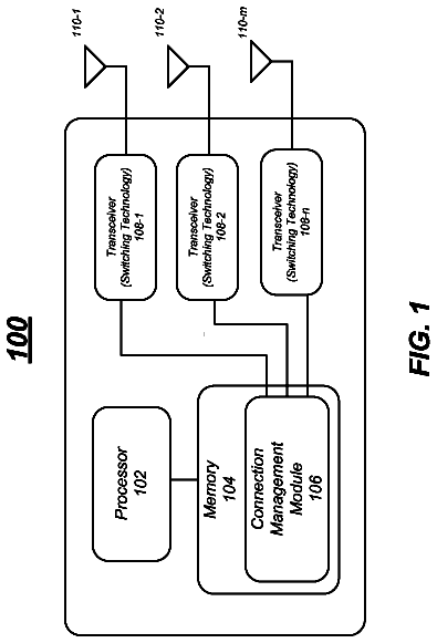
FIG. 13 is a block diagram of a base station.
Detailed description of the present invention
Embodiments of the present invention relate to downlink (DL) multi-user MIMO (MU-MIMO) transmission in cellular and beyond-cellular deployments. Embodiments of the invention rely on the use of a palette of architectural choices to perform the DL MU-MIMO transmission. Each architecture enables joint scheduling training and transmission across the cellular topology. In one embodiment, each architecture is characterized by its own MU-MIMO precoding scheme, operating over one or more BSs (or RAUs), its own (cell or cluster) reuse factor, and its own uplink-training scheme. In one embodiment, the training scheme in particular is self characterized by the size of the UT pilot training set, the pilot reuse factor and (rules for) the pilot reassignment method across the topology.
Embodiments of the invention leverage the use of bin classes whereby one or more bin classes are associated with each one of the DL MU-MIMO transmission architectures. The bin class concept allows efficient binning, or "pairing" across the topology of UT sets (based on geographic and/or other slowly varying nominal signal strength information) for simultaneous transmission. In this way, several bin classes are formed, and the scheduling-slot resources are split among the bin classes. Within the group of resources that are allocated to a single bin class, only users from this bin class (across the topology) are scheduled and served. The advantage of this scheme is that each bin class is independently served over its allocated resources, by an architecture that can optimized for the given bin class. By properly forming bin classes, by systematically choosing UT groups from a bin class for joint transmission, and by performing joint DL MU-MIMO transmission via a class-optimized architecture, efficient cellular and beyond-cellular schemes can be enabled with high edge and cell throughput performance.
Embodiments of the invention leverage the use of geographical information and/or slowly varying nominal received signal-strength information between user-terminals (UTs) and base stations (BSs) or remote antenna units (RAUs), to systematically and schedule groups of UTs in cells (or clusters of cells) across the deployment for simultaneous transmission. In one embodiment, simultaneous transmission involves an uplink training mechanism and an associated MU-MIMO transmission scheme that are chosen in a group-optimized manner across the deployment. The scheme thus enables the use of UT/geographic-location optimized MIMO precoders, coupled with enabling pilot assignments for uplink training.
In the following description, numerous details are set forth to provide a more thorough explanation of the present invention. It will be apparent, however, to one skilled in the art, that the present invention may be practiced without these specific details. In other instances, well-known structures and devices are shown in block diagram form, rather than in detail, in order to avoid obscuring the present invention.
Some portions of the detailed descriptions which follow are presented in terms of algorithms and symbolic representations of operations on data bits within a computer memory. These algorithmic descriptions and representations are the means used by those skilled in the data processing arts to most effectively convey the substance of their work to others skilled in the art. An algorithm is here, and generally, conceived to be a self-consistent sequence of steps leading to a desired result. The steps are those requiring physical manipulations of physical quantities. Usually, though not necessarily, these quantities take the form of electrical or magnetic signals capable of being stored, transferred, combined, compared, and otherwise manipulated. It has proven convenient at times, principally for reasons of common usage, to refer to these signals as bits, values, elements, symbols, characters, terms, numbers, or the like.
It should be borne in mind, however, that all of these and similar terms are to be associated with the appropriate physical quantities and are merely convenient labels applied to these quantities. Unless specifically stated otherwise as apparent from the following discussion, it is appreciated that throughout the description, discussions utilizing terms such as "processing" or "computing" or "calculating" or "determining" or "displaying" or the like, refer to the action and processes of a computer system, or similar electronic computing device, that manipulates and transforms data represented as physical (electronic) quantities within the computer system's registers and memories into other data similarly represented as physical quantities within the computer system memories or registers or other such information storage, transmission or display devices.
The present invention also relates to apparatus for performing the operations herein. This apparatus may be specially constructed for the required purposes, or it may comprise a general purpose computer selectively activated or reconfigured by a computer program stored in the computer. Such a computer program may be stored in a computer readable storage medium, such as, but is not limited to, any type of disk including floppy disks, optical disks, CD-ROMs, and magnetic-optical disks, read-only memories (ROMs), random access memories (RAMs), EPROMs, EEPROMs, magnetic or optical cards, or any type of media suitable for storing electronic instructions, and each coupled to a computer system bus.
The algorithms and displays presented herein are not inherently related to any particular computer or other apparatus. Various general purpose systems may be used with programs in accordance with the teachings herein, or it may prove convenient to construct more specialized apparatus to perform the required method steps. The required structure for a variety of these systems will appear from the description below. In addition, the present invention is not described with reference to any particular programming language. It will be appreciated that a variety of programming languages may be used to implement the teachings of the invention as described herein.
A machine-readable medium includes any mechanism for storing or transmitting information in a form readable by a machine (e.g., a computer). For example, a machine-readable medium includes read only memory ("ROM"); random access memory ("RAM"); magnetic disk storage media; optical storage media; flash memory devices; etc.
General Overview
Embodiments of the invention focus on methods for scheduling, training, and MU-MIMO transmission in cellular and beyond-cellular deployments with reciprocity-based training, and can enable high spectral-efficiency transmission in the downlink of these networks. Embodiments of the invention are applicable to settings involving sets of transmit (collocated or non-collocated) antennas simultaneously transmitting to UTs in their coverage area. The methods disclosed herein are also applicable to the case, where within each transmission resource block (RB), the base-station (BS) controller, controlling the joint transmission from the cluster of antennas, schedules a subset of UTs for transmission, generates multiple spatial streams (one or more for each UT), superimposes them, and simultaneously transmits them using what is commonly referred to as multi-user multiple-input multiple-output (MU-MIMO) transmission methods.
Embodiments of the invention rely on the notion of binning users across the cellular topology and separating them into bin classes, with each bin class allocated a fraction of the time-frequency resources for transmission via a bin-class specific training and MU-MIMO transmission scheme applied across the topology. Embodiments of the invention leverage the use of geographical and possibly slowly varying received signal strength information between UTs and BSs (or RAUs) to first assign each UT to a bin within a bin class. Then each bin class is served over a fraction of the available resources, without being interfered from the remaining bin class transmission. Within the scheduling slots residing in resources allocated to a single bin class, groups of UTs within the bin class are selected across the deployment and a bin-class specific training and downlink MU-MIMO precoding operation is used across the topology to simultaneously transmit to the scheduled UT set. In addition, pilot-assignments used for uplink training can be pilot-contamination optimized for the UT scheduled group. In one embodiment, this is performed as described in U.S. patent application Ser. No. 13/081,373, filed Apr. 6, 2011, "Method and Apparatus for the Joint Design and Operation of Pilot-Reuse Methods in Reciprocity-Based Training Schemes for Downlink Multi-User MIMO".
As disclosed herein, users are binned in their preferred bin/architecture class, where each bin class is associated with one of the many possible architectures, and each architecture corresponding to a unique set of a precoder, reuse factor, pilot reuse factor, and (maximum) number of users that can be served simultaneously in each cell (or cluster). In general, scheduling users within a bin-class can be performed by selecting in e.g., round-robin fashion (up to) the a priori optimized number of users, performing uplink training simultaneously for all selected users, and then scheduling all or a subset of those users (e.g., by means of a scheduling criterion).
In one embodiment, the wireless communication system for wireless communication information with user terminals includes multiple base stations located in cells in a topology and a base station controller. The base station controller controls joint transmission of the plurality of base stations by allocating a subset of time-frequency resources in a time-frequency plane to each distinct bin class, where each bin class includes one or more bins of user terminals across the topology, and the user terminals in the one or more bins of each bin class are served across the topology by the subset of time-frequency resources. The base stations perform joint downlink MU-MIMO transmission using multiple bin class-dependent wireless transmission architectures at the base stations, where one or more bin classes is associated with one of the bin class-dependent architectures, and wherein each bin class-dependent architecture uses a different combination of scheduling and MU-MIMO transmission across the topology for that bin class.
In the following, a sample set of embodiments are described as well as their potential benefits. Embodiments are illustrated in the context of the one-dimensional (1D) linear topology of BSs such as shown, for example, in FIG. 1. However, one skilled in the art would recognize that embodiments of the present invention are applicable to all topologies and are not limited to 1D linear topologies.
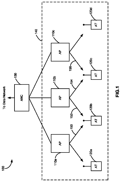
FIG. 1 illustrates geographic (pathloss-based) user binning according to one embodiment. Referring to FIG. 1, the b-th cell spans [b-1/2, b+1/2) and BS b is located at b. For illustration purposes, the focus is on a "pathloss with fast fading" channel model, whereby the nominal received signal strength between a TX antenna (either at a BS or at a remote antenna unit (RAU)) and a UT antenna equals the pathloss between the two antennas, and this pathloss value is only a function of the distance between the two antennas. In this case, embodiments of the invention can be viewed as geographical-location optimized scheduling/training and transmission.
In one embodiment, each cell is split into 2K bins (each of size e.g., 1/2K) for some K>1. Let (k,c) for k=1, 2, . . . , 2K, denote the k-th bin in cell c (enumerated from left to right, as (1,c) (2,c), . . . , (2K,c)), as shown in FIG. 1. Bin class k is formed by all the bins (k,c) for all c, and users in (cell) bin class k across the topology are jointly served over a subset of time-frequency slots, such as shown, for example, in FIG. 2.
Referring to FIG. 2, the time-frequency (TF) plane is split into groups of slots, and each group is used across the topology to serve users in a particular (distinct) bin class. In particular, within any scheduling slot serving a particular bin class, users from bins in the bin class are chosen for simultaneous uplink training and DL MU-MIMO transmission. That is, within the group of time-frequency slots serving a given bin class, only users residing in bins associated with the given bin class are served across the topology. In the illustrations provided herein, it is assumed for simplicity that a fixed number of time-frequency slots, L.sub.T, are allocated for training within each scheduling slot, although in practice this may also be an optimization variable.
In one embodiment, users are split into bins, and bins across the topology are used to form bin classes. Each bin class (i.e., UTs falling in bins within a bin class) is given a fraction of the available time-frequency resources and an architecture is chosen (e.g., a priori) for serving the bin class over this fraction of the time-frequency resources. In one embodiment, the allocation of the available time-frequency resources is performed by a base station controller (e.g., the base station controllers of FIGS. 1, and 3-11) that is communicably coupled with the base stations. In an alternative embodiment, an allocation unit, separate from the base station controller, controls the allocation. In one embodiment, the controller specifies the mapping of time-frequency slots to bin-classes getting served. In one embodiment, for each bin-class, the controller also specifies the architecture to be used (including the number of users served, the precoder, the pilot sequences, and all these can in principle be base-station specific). Also within the set of time-frequency slots that are allocated to a bin class, with frequency reuse, the controller may specify the subset of slots during which the BS is transmitting. Similarly, in one embodiment in the cluster transmission case, the controller also specifies the mapping between subsets of slots and BS clusters.
In one embodiment, the architecture is chosen from, e.g., a palette of available architecture choices. In one embodiment, the palette or architectures comprise cellular and cluster architectures that can be represented by a triplet (F, C, Z) and a pilot-reuse factor Q, whereby C represents the number of BSs engaging a cooperative transmission (C=1 corresponds to cellular, while C>1 corresponds to cluster transmission); F represents the architecture (cellular or cluster) reuse-factor; and Z represents the number of (closest) BSs from which any given UT experiences no interference.
In one embodiment, the palette only includes cellular architectures (C=1), and 2K bin classes are defined, whereby the k-th bin class is defined as the bins in the set X.sub.k={(k,c); for all c}. Consequently, a palette of cellular architectures is considered as a choice for serving all UTs falling within one of the bins in the set X.sub.k={(k,c); for all c}. In one embodiment, any given cellular architecture is characterized by: its reuse factor, F; its pilot reuse factor, Q, together with a method for geographically reassigning pilots across the deployment; and its own MU-MIMO precoder.
FIG. 3 illustrates an example showing cellular transmission within a band serving a particular bin class. Referring to FIG. 3, within each cell, S users from the bin (belonging to the bin class that is being served on this scheduling slot) are scheduled. Reciprocity-based training is performed, followed by DL MU-MIMO cellular transmission. Note that the dashed lines represent intercell interference, while the solid lines represent transmissions containing useful signals for the users in the bin.
FIGS. 4-8 depict several such cellular (F, 1, Z)-type architectures according to different embodiments of the present invention. FIGS. 4, 6, and 8, in particular, depict reuse-1 architectures (i.e., F=1), whose precoders vary with respect to zero-forcing constraints that they are required to satisfy. FIGS. 5 and 7 correspond to reuse-2 versions of the architectures in FIGS. 4 and 6, respectively. Note that in all the figures, the bin class is implicitly identified by a variable "x", which denotes the distance between the center of a cell bin and the cell BS (or equivalently the center of the cell).
FIG. 4 illustrates a (1,1,0) scheme, corresponding to reuse-1 cellular Linear Single-User Beamforming (LSUBF) according to one embodiment. Referring to FIG. 4, within each cell, S users in the bin (belonging the bin class being served) are chosen for training and transmission. After uplink training, base station b simultaneously transmits data streams to the S scheduled users with a LSUBF precoder.
FIG. 5 illustrates a (2,1,0) scheme, corresponding to reuse-2 cellular LSUBF according to one embodiment. Referring to FIG. 5, within each of the two bands serving the bin class, half of the cells are active (either the odd or the even ones). For each active cell b in a band, in each scheduling slot, S users in the bin (belonging to the bin class being served) are chosen for training and transmission. After uplink training, base station b simultaneously transmits data streams to the S scheduled users with a LSUBF.
Note that in one embodiment the number of users, S, that the precoder of a given (F, 1, Z) scheme can serve in each cell is a parameter that can range between 1 and S.sub.max, and can be optimized independently for each bin class, i.e., for each set X.sub.k. The maximum number of users, S.sub.max, that can be scheduled in any given cell simultaneously is given by S.sub.max.ltoreq.floor(L.sub.T/Q), where floor(x) denotes the largest integer not exceeding x. Note, however, that S.sub.max depends indirectly on the specific precoder CSI requirements. For instance, to operate a LZFBF in a given active cell (e.g., in FIG. 6) requires the CSI between each of the S scheduled UTs in the cell and the cell BS. For cell-center users (e.g., users in bin classes X.sub.K, X.sub.K+1), a pilot reuse factor of Q=1 may suffice, regardless of the reuse factor, F, yielding for LZFBF the condition S.ltoreq.S.sub.max=max{L.sub.T, M}, with M denoting the number of BS antennas. Of course, any Q.gtoreq.1 may be used for serving X.sub.K and X.sub.K+1, yielding S.ltoreq.S.sub.max=max {floor(L.sub.T/Q), M}. A training scheme with Q=2 for instance yields better CSI than the system with Q=1. However, it may also restrict the maximum number of simultaneously scheduled users and thereby the provided multiplexing gains. Which Q value is preferred depends on the architecture being considered, the bin class, and the specific M and L.sub.T values. As one example, consider a center user with a reuse-1 architecture using LZFBF (i.e., the architecture in FIG. 6). If M is small enough with respect to L.sub.T, i.e., if, M.ltoreq.L.sub.T/2, then S.sub.max=M for both Q=1, and Q=2, pilot-reuse. Given an optimal number of users S for Q=1 pilot reuse, the Q=2 system can also schedule the same number of users, S, and would yield higher performance with S users, due to its superior channel estimates. As a result, Q=2 would be preferred in place of Q=1. At the other extreme, however, where M>L.sub.T, the Q=1 scheme could schedule up to twice as many users than a Q=2 scheme. In such cases, using Q=1 is usually a better choice in terms of maximizing the bin rates.
Embodiments of the invention allow the use of different reuse factors in serving different bin classes. For example, consider serving users with LZFBF, with either of the architectures in FIGS. 6 and 7. FIG. 6 illustrates a (1,1,1) scheme, corresponding to reuse-1 cellular Linear Zero-Forcing Beamforming (LZFBF) according to one embodiment. Referring to FIG. 6, within each cell, S users in the bin (belonging to the bin class being served) are chosen for training and transmission. After uplink training, base station b simultaneously transmits data streams to the S scheduled users, with a LZFBF precoder. Note that, due to the zero-forcing conditions enforced by the LZFBF precoders, each served UT in a bin does not experience interference from the signals transmitted by the serving base station that are intended for other UTs.
FIG. 7 illustrates a (2,1,1) scheme, corresponding to reuse-2 cellular LZFBF according to one embodiment. Referring to FIG. 7, within each of the two bands serving the bin class, half of the cells are active (either the odd or the even ones). For each active cell b in a band, and in any given scheduling slot, S users in the bin (belonging to the bin class being served) are chosen for training and transmission. After uplink training, base station b simultaneously transmits data streams to the S scheduled users, with a LZFBF precoder. Due to zero forcing, each served user in a bin does not experience interference from signals transmitted to other UTs by the serving base station.
Thus, with respect to serving users with LZFBF in FIGS. 6 and 7, for edge users, e.g., users in bin classes X.sub.1, X.sub.2K, the reuse-1 architecture yields low SINRs, and thereby low per-user rates. This is true even with high pilot reuse due to the high levels of interference from neighboring transmitting stations. Although the reuse-2 architecture in FIG. 7 incurs a factor-of-two loss in multiplexing gain (as it serves only every other bin in the class on each band), the fact that transmissions are turned off from cells that are neighboring each active cell means significantly improved edge-user SINRs with respect to the reuse-1 case. For center users, on the other hand, the reuse-1 architecture in FIG. 6 is preferable, since the improvement in SINR offered by the reuse-2 architecture in FIG. 7 is outweighed by the loss in multiplexing gains due to the reuse-2 factor.
In one embodiment, only reuse-1 and reuse-2 LZFBF architectures are considered as choices for serving all the users in the topology. Transmission resources are split into 2K parts, with the k-th part used to serve bin class k. Bin class k, for each value of k in {K-m+1, . . . , K, K+1, . . . , K+m} for some m is served with a reuse-1 LZFBF architecture, i.e., (1,1,1), while the rest of the bin classes are served with a reuse-2 LZFBF architecture, i.e., (2,1,1). In one embodiment, the number of users scheduled by each architecture and the pilot reuse scheme is optimized (with off line optimization) for each bin class. Pilots can be reassigned randomly per active cell or techniques can be employed such as those described in U.S. patent application Ser. No. 13/081,373, filed Apr. 6, 2011, "Method and Apparatus for the Joint Design and Operation of Pilot-Reuse Methods in Reciprocity-Based Training Schemes for Downlink Multi-User MIMO".
FIG. 8 illustrates a (1,1,2) scheme, corresponding to reuse-1 cellular LZFBF with nearest-cell interference nulling according to one embodiment. Referring to FIG. 8, within each cell, S users in the bin (belonging to the bin class being served) are chosen for training and transmission. After uplink training, base station b simultaneously transmits data streams to the S scheduled users, with a LZFBF precoder subject to also interference constraints to the nearest next-cell served users. Due to zero forcing, each served user in a bin does not experience interference from the signals transmitted to other UTs from the two closest base stations.
The binning classes may also take other forms. FIGS. 9 and 10 show two cluster architectures serving "bin clusters" in unison across the topology. In these cases, the bin classes correspond to collections of clusters of bins. In particular, denoting by cluster b the cluster of BSs comprised of BSs b and b+1, the bin classes comprise all cluster bins formed by pairs of bins of the form [k,b]={(2K-k+1,b),(k,b+1)} for k=1, . . . , K. The k-th (cluster) bin class corresponds to the collection of all cluster bins of the form [k,b]. Similarly to the cellular case, in FIGS. 9 and 10, the bin class being served is implicitly identified by the variable "x", which denotes the distance between the center of the left cell bin in the cluster bin and the left cell BS (or equivalently the center of the left cell). Unlike, the cellular case, however, where 1/2<x<1/2, in the cluster case 0.ltoreq.x<1/2. FIGS. 9 and 10 also imply an additional set of potential constraints in selecting UTs and assigning pilots in these cluster cases.
The description continues in the full USPTO document.
 Lapsed, fee not paid9 drawings