 Lapsed, fee not paid4 drawings
Industrial Equipment · US 8,636,345 B2
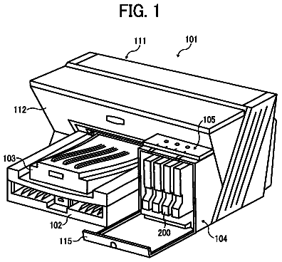
Supply tube connectors for connection with an ink container
A connector for connecting to an ink container.
US 8,636,359 B2 · Assignee: Essilor International (Compagnie General d'Optique) · Inventors: Warden; Laurence et al.
Sheet 1 of 16 from the published document. All sheets in the USPTO PDF
A method of customizing vision correction including measuring optical aberration data of a patient's eye and calculating a lens definition based on the optical aberration data, wherein calculating the lens definition comprises calculating a correction of at least one low order aberration and at least one high order aberration and is based at least partly on the patient's pupil size.
The human eye, namely the cornea and lens, can exhibit a variety of optical aberrations that diminish the optical performance of the eye, resulting in blurred vision. The correction of blurred vision by fitting patients with lenses has typically been limited to the correction of low order aberrations only, such as defocus and astigmatism. Traditionally, high order aberrations, e.g. those describable with Zernike polynomials of the third order or higher, could not be corrected using lenses. In addition, due to lens manufacturing limitations and expenses, defocus and astigmatism are typically only corrected in discrete steps, with any correction being made to the nearest one quarter (0.25) diopter. Unfortunately, the resolution of one quarter (0.25) diopter results in incomplete vision correction.
1 of 16 drawing sheets so far from the published document, cropped to the drawing. Every sheet is in the USPTO PDF.
What the patent claimed, word for word. All of it is now free to use.
The present invention relates to systems and methods relating to manufacturing optical lenses for correcting aberrations of optical systems such as the human eye.
The human eye, namely the cornea and lens, can exhibit a variety of optical aberrations that diminish the optical performance of the eye, resulting in blurred vision. The correction of blurred vision by fitting patients with lenses has typically been limited to the correction of low order aberrations only, such as defocus and astigmatism. Traditionally, high order aberrations, e.g. those describable with Zernike polynomials of the third order or higher, could not be corrected using lenses. In addition, due to lens manufacturing limitations and expenses, defocus and astigmatism are typically only corrected in discrete steps, with any correction being made to the nearest one quarter (0.25) diopter. Unfortunately, the resolution of one quarter (0.25) diopter results in incomplete vision correction.
The system, method, and devices of the invention each have several aspects, no single one of which is solely responsible for its desirable attributes. Without limiting the scope of this invention as expressed by the claims which follow, its more prominent features will now be discussed briefly. After considering this discussion, and particularly after reading the section entitled "Detailed Description of Embodiments" one will understand how the features of this invention provide advantages that include convenient and economical methods of manufacturing optical lens and lens blanks.
One embodiment is a system for customizing vision correction. The system includes a measurement system configured to measure patient's vision parameters and to create measured optical aberration data. The system further includes a calculation system configured to receive the measured vision parameters and optical aberration data and to determine a lens definition based on the vision parameters and measured optical aberration data. The system further includes a fabrication system configured to produce a correcting lens based on the lens definition wherein the lens definition comprises a correction of at least one high order aberration.
Another embodiment is a method of customizing vision correction. The method includes measuring optical aberration data of a patient's eye. The method further includes calculating a lens definition based on the optical aberration data. Calculating the lens definition includes calculating a correction of at least one low order aberration and at least one high order aberration. The method further includes fabricating a correcting lens based on the lens definition.
Another embodiment is a system for customizing vision correction. The system includes a measurement system configured to measure patient's vision parameters and to create measured optical aberration data. The system further includes a calculation system configured to receive the measured vision parameters and optical aberration data and to apply a metric so as to determine a lens definition defining a correction to at least one high order aberration based on the vision parameters and measured optical aberration data. The system further includes a fabrication system configured to produce a correcting lens based on the lens definition.
Yet another embodiment is system for customizing vision correction, comprising a calculation system configured to receive measured vision parameters and optical aberration data and to apply a metric so as to determine a lens definition defining a correction to at least one high order aberration based on the vision parameters and measured optical aberration data.
FIG. 1 is a flow chart depicting a process for producing a spectacle lens.
FIG. 2 is a flow chart depicting an embodiment of a method of manufacturing a lens for correcting optical aberrations as part of the process of FIG. 1.
FIG. 3 is a flow chart depicting another embodiment of a method of manufacturing a lens blank as a part of a method of making a lens, such as depicted in FIG. 1.
FIG. 4A illustrates a lens blank at one step of the method depicted in FIG. 3.
FIG. 4B illustrates the lens blank of FIG. 4A at another step of the method of FIG. 3.
FIG. 4C illustrates the lens blank of FIG. 4A at the completion of the method of FIG. 3.
FIG. 4D graphically illustrates another embodiment of a method of manufacturing a lens, similar to the method depicted in FIG. 3.
FIG. 4E is a diagram illustrating an embodiment of a method, similar to the embodiment of FIG. 4D, of creating an optical element by dispensing a mixture of low and high refractive indices formulations between these two molds.
FIG. 5 is a flow chart depicting another embodiment of a method of making an optical lens as part of the process of FIG. 1.
FIG. 6 is a flow chart depicting an embodiment of a method of making a lens for correcting optical aberration similar to the method depicted in FIG. 1, but using a mold.
FIGS. 7A-7E graphically illustrate steps of making a lens, such as in the method depicted in FIG. 6.
FIGS. 7F-7J graphically illustrate steps of a method making a lens similar to the method depicted in FIGS. 7A to 7E, except that the layer has a generally uniform thickness and is composed of varying proportions of materials to vary the index of refraction across the surface of the lens.
FIG. 8 is a flow chart depicting an embodiment of a method of making a lens blank using a free standing filmy gel of polymer material similar to the method depicted in FIG. 6.
FIG. 9 is a flow chart depicting an embodiment of a method of making a lens blank using a free standing filmy gel of polymer material into a lens blank for use in, e.g., an embodiment of the method of FIG. 1.
FIG. 10 is a simplified block diagram depicting one embodiment of a system for producing spectacle lens, e.g., using one embodiment of the method of FIG. 1.
FIG. 11 is one embodiment of a method of producing spectacles using an embodiment of a system such as depicted in FIG. 10.
FIG. 12 is one embodiment of a method of producing customized framed lenses.
FIG. 13 graphically illustrates another embodiment of a method of manufacturing a lens having a layer with a varying thickness.
The following detailed description is directed to certain specific embodiments of the invention. However, the invention can be embodied in a multitude of different ways as defined and covered by the claims. In this description, reference is made to the drawings wherein like parts are designated with like numerals throughout.
Spectacle lens are typically formed by grinding the lens blank to correct the measured optical aberrations and edging a lens blank to fit a pair of spectacle frames. This correction is typically limited to low order aberrations. In addition, the corrections are typically incomplete in that grinding is typically performed to a margin of 0.25 D.
By using a device that measures wavefront aberrations in the eye of patient, much more precise measurements of a patient's eye can be obtained. The resulting measurements can be used to calculate an optimized lens definition. In one embodiment, the lens definition can define a pattern of refractive index that corrects one or more optical aberrations in an optical path through the lens that, when manifested in an optical lens, such as a spectacle lens, corrects the wavefront aberrations of the patient more precisely than is typically possible. Patients will thus be able to see at very near the peak of their own optical capabilities.
It is to be appreciated that, as used herein, "correction" of optical aberrations does not necessarily mean that the optical aberrations are completely eliminated but, rather, is to be understood to generally mean reducing, minimizing, or optimizing the optical aberrations. Moreover, because in some instances increasing certain high order aberrations has been found to improve vision, "correction" of aberrations can also include adding or increasing certain optical aberrations. An optical element may include a thick or thin lens blank, a plano lens, a corrective lens such as a spectacle lens, a contact lens, an optical coating, an intraocular lens, or any other light transmissive component including combinations of other optical elements. A plano optical element, i.e., one that does not possess any refractive power, may be flat, or may have a curve for cosmetic reasons, e.g. to have an appearance mimicking a standard spectacle lens.
FIG. 1 is a top level flow chart illustrating a method 100 of making customized lens. Beginning at a step 110, a patient's eye is measured. In one embodiment, the patient's vision parameters, such as low order and/or high order aberrations are measured using an aberrometer (comprising a wavefront sensor, for example). The aberrations can be measured using a wavefront sensor, such as a Shack-Hartmann, diffraction grating, grating, Hartmann Screen, Fizeau interferometer, ray tracing system, Tscheming aberrometer, skiascopic phase difference system, Twymann-Green interferometer, Talbot interferometer, for example. Exemplary aberrometers are described in more detail in U.S. Pat. No. 6,721,043 to Platt. B. et. al. in "Light Adjustable Aberration Conjugator", which is hereby incorporated by reference in its entirety. Other embodiments of an aberrometer are disclosed in U.S. patent application Ser. No. 10/076,218, entitled "APPARATUS AND METHOD FOR DETERMINING OBJECTIVE REFRACTION USING WAVEFRONT SENSING," filed Feb. 13, 2002; and U.S. patent application Ser. No. 10/014,037, entitled "SYSTEM AND METHOD FOR WAVEFRONT MEASUREMENT," filed Dec. 10, 2001, each of which is hereby incorporated by reference in its entirety. In one embodiment, the vision parameters may include data obtained by testing the patient's vision through a trial, or test, lens that is configured to correct one or more high or low order optical aberrations.
In addition to measuring aberrations, other vision parameters can be obtained such as the patient's vertex distance, pupil size, pupil distance, frame information, gaze, or x-y tilt. Further details of taking such measurements are described in U.S. Pat. No. 6,682,195, entitled "CUSTOM EYEGLASS MANUFACTURING METHOD," issued on Jan. 27, 2004, which is hereby incorporated by reference in its entirety.
Moving to step 120, a pattern of refraction in an optical lens is calculated to correct the measured aberrations. The pattern of refraction can be effected in an optical element by, for example, defining a two dimensional pattern of refractive index across the face of the optical element or by varying the thickness of a layer of material comprising the optical element to vary the refractive index and thereby define the pattern of refraction. For example, standard spectacle lens typically defines a pattern of refraction by varying the curvature of the lens material, and thus the thickness of the lens material, over the surfaces of the lens. The curvature of the lens, along with the refractive index of the lens material, defines the pattern of refraction of the standard spectacle lens. Such standard lenses typically correct one or more low order optical aberrations. In one embodiment, the pattern of refraction is at least partially defined in terms of sphere, cylinder, and axis. In such an embodiment, a further pattern of refraction for correcting high order aberrations and residual aberrations resulting from, for example, grinding errors can be further calculated for application to the lens. In other embodiments, the pattern of refraction can be calculated in terms of low and high order Zernike polynomials for application to a material that can be processed or cured to alter its refractive index.
In one embodiment, the vision parameters are used by a vision metric to optimize the lens definition. The lens definition can include the wavemap, a pattern of refraction, a prescription in terms of sphere, cylinder, and axis, or any other relation to a pattern of refraction or correction. In addition, the lens definition may include an optical center, multiple optical centers, single correction zones, multiple correction zones, transition zone, blend zone, swim region, channel, add zones, vertex distance, segmental height, off-axis gaze zone, logos, invisible markings, etc.
Next at step 130, a lens is manufactured to correct both low and high order optical aberrations. One embodiment of such a lens is disclosed in more detail in U.S. patent application Ser. No. 10/218,049, entitled "APPARATUS AND METHOD OF CORRECTING HIGH ORDER ABERRATIONS OF THE HUMAN EYE," filed Aug. 12, 2002, herein incorporated by reference in its entirety. Embodiments of methods of manufacturing the lens may include number of different methods for forming a lens having a calculated pattern of refractive index, such as are described in more detail herein, including depositing of a layer that is cured to include the calculated pattern of refraction, grinding or freeform surfacing of a lens surface, cast molding and combinations thereof.
FIG. 2 is a flow chart depicting one embodiment of a method 130 of manufacturing optical lens blank that can receive a pattern of refractive index that is calculated based on the wavefront aberrations from, e.g., a human eye. The method 130 begins at a step 210, where a photosensitive gel layer is formed between a first and second optical element. In one embodiment is a thick and thin lens. Other embodiments can include two thick lenses or two thin lenses. A thick optical lens is generally thicker, can be plano, and generally refers to an optical element that can provide corrective power. While either a thick or thin lens can be contoured to change the refractive power of the element, the thicker lens provides a greater range for contouring. Such contouring can include grinding and polishing, laser ablation, or freeform surfacing. Desirably, the front optical element, the one on which light into the eye is initially incident, is a thin lens that generally provides no power. Note that the radius of curvature of the front optical element generally defines the refractive power of the optical lens blank. The selection of a thick or thin lens for each optical element can be made on the basis of the desired corrective power of the final optical blank. For example, if a higher power lens is desired, two thick lenses can be used. If only minimal low order correction is desired in a particular lens, two thin lenses may be used.
The photosensitive gel layer can be selectively cured to vary its index of refraction. For example, it can be cured in a pointwise, stepwise, or continuous manner to define a two dimensional pattern of refraction that corrects one or more optical aberrations in an optical path through the lens. As used herein, a material that can be cured in such a way may be referred to as having a selectively variable index of refraction. The pattern of refraction of the layer can be produced so as to define a correction to one or more optical aberrations. It is to be appreciated that while certain embodiments of this and other methods are discussed herein with respect to a photosensitive gel layer, other embodiments can use a layer of any other material that has a selectively variable index of refraction, e.g., that can be processed or cured to vary the index of refraction.
In one embodiment, the photosensitive gel layer is formed of a polymer gel that is first formed in, for example, a large sheet. A co-pending U.S. patent application, entitled "Monomers And Polymers For Optical Elements", filed on Sep. 7, 2004 as U.S. Ser. No. 10/936,030, now U.S. Pat. No. 7,371,804, and incorporated by reference in its entirety, discloses embodiments of the photosensitive gel layer. A preferred embodiment is formed using a composition including a matrix polymer having a monomer mixture dispersed therein, the matrix polymer being selected from the group consisting of polyester, polystyrene, polyacrylate, thiol-cured epoxy polymer, thiol-cured isocyanate polymer, and mixtures thereof; the monomer mixture comprising a thiol monomer and at least one second monomer selected from the group consisting of ene monomer and yne monomer.
In one embodiment, a sheet of this matrix polymer, or gel, is formed. A portion of this sheet is placed between two optical elements to form a lens blank. A single large sheet can be formed in bulk with portions diced and used to form many lens blanks. The two optical elements are affixed to form a lens blank. The first and second optical elements can be plano lens or have correction power. In one embodiment, lens blanks are prepared to have a range of corrective power in the first and/or second lens, e.g., in a range separated by 0.25 diopter, or 1 diopter. In preferred embodiment, one or both of the optical elements are a thick lens that can contoured, for example, by grinding and polishing, to provide at least partial correction of one or more low order aberrations. Next at step 215, in such an embodiment, one or both outer surfaces of the optical elements may be contoured. In another embodiment, the lenses can be contoured before affixing the lenses together to form the lens blank. The lenses can be contoured using conventional grinding and polishing methods, or by freeform surfacing using a three axis turning machine such as manufactured by Schneider Optics, LOH, Gerber Coburn Optical, or otherwise formed to provide at least partial correction of optical aberrations. As used herein freeform surfacing refers to any method of point-to-point surfacing or machining.
Next at step 220, a pattern of refraction or refractive index, such as calculated in step 120 of method 100, is formed in the photosensitive gel layer. This pattern is configured to correct optical aberrations in a human eye. In one embodiment, the pattern of refraction formed in the photosensitive gel is calculated to correct high order aberrations and low order aberrations that are not otherwise corrected by, for example, the thin lens of a lens blank, or surfacing of the thin lens from a lens blank.
In one embodiment, this pattern of refractive index can be formed using a source of radiation, e.g., ultraviolet light, having a two dimensional grayscale pattern. A two dimensional grayscale pattern of radiation includes any pattern of radiation that varies in intensity, e.g., grayscale, in a two dimensional pattern when directed onto a surface, e.g., of an optical element. In one embodiment, radiation is directed through a photomask to control the amount of radiation received at different points in the optical element. The photomask can comprise regions that are essentially opaque to the radiation, regions that are essentially transparent to the radiation, and regions that transmit a portion of the radiation. The lens blank is exposed to the radiation for a predetermined time to cure and partially cure the photosensitive polymer such that the pattern of refractive index is formed in the lens blank. Other embodiments can use digital mask systems such as Digital Light Projector (DLP) along with a UV light source. The UV light source can include a UV Vertical Cavity Surface Emitting Laser (VSCEL), triple YAG laser, or a UV-LED.
Moving to step 230, the blank can be edged and mounted to fit a pair of frames for use by the patient. In one embodiment, the step 210 can be performed en mass to provide an inventory of lens blanks that can be conveniently processed (for example, according to steps 210 and 230) at, in some embodiments, a different location, e.g., an optometrist's office where the patient's eye is also measured.
FIG. 3 is a flow chart depicting another embodiment of a method for forming the photosensitive gel layer between a lens blank and a lens cover such as in step 210 of FIG. 2. Beginning at step 310, passages are formed in the lens blank. The lens blanks can be formed of CR-39 or other suitable materials such as polycarbonate, Finalite.TM. (Sola), MR-8 monomer (Mitsui), or any other material known in the art. In one embodiment, these passages can be drilled or cut into the lens blank. Generally, the lens blank is larger than the final lens that is to be fit into a spectacle frame. Thus, the area in which the passages are formed is removed from the final lens and does not inhibit the optical correction of the lens. In another embodiment, the passages are formed along with the lens blank, e.g., in a mold or press. It is to be appreciated that while two passages are discussed herein, additional passages can be formed in the lens blank to, e.g., allow faster or more even filling of the cavity between the lens blank and lens cover.
Next at step 320, the lens blank is mated with the lens cover by spacing the lens cover and lens blank at a predetermined distance determined by a spacer, or gasket. In one embodiment, the spacer is a solid material placed between the lens blank and cover. However, any method of maintaining the predetermined distance between the blank and cover can be used. Moving to step 330, a seal is formed around the perimeter of the lens blank and lens cover to form a sealed cavity therebetween. In one embodiment, an adhesive spacer with a thickness in the range of 1 to 100 mil is sandwiched between the lens blank and cover lens to form and seal the cavity. In one embodiment, the adhesive spacer is approximately 20 mil thick.
In another embodiment, mating the lens blank and lens cover to make a cavity therebetween includes a taping method. A cavity is formed by holding two lens blanks apart mechanically, e.g., by clamps or a jig, to control the thickness of the cavity. A tape or similar material is applied around the edges of the mated lens blank and cover to form a sealed cavity by wrapping the deformable elastic tape or a rubber gasket over the edges of two lens blanks and holding them together with a clamp. Further, in one embodiments, rather than forming a passage through the lens blank at step 310, the passage is formed through the spacer or tape, e.g., via inserting a syringe or other dispenser through the tape or gasket.
Continuing to step 340, a curable material formulation, in one embodiment, a photosensitive material, made, e.g., of Thiol-Ene, or a composition as described above, is mixed, degassed and transferred to a syringe in a clean environment. Using a fluid dispenser, such as a dispenser from EFD, Inc., or a mechanical-type dispenser, such as a syringe, the mixed formulation is injected through one of the passages into the cavity while the passage is for venting of the air from the cavity. In some embodiments, the material may be dispensed through a passage in the spacer or seal. In one embodiment, such a passage may be formed by the syringe used to dispense the curable material. Next at step 350, the injected lens blank is placed in an oven maintained at an elevated temperature (for example, approximately 75.degree. C.) to cure the injected material to form the photosensitive film. In another embodiment, the curing process can be performed at room temperature, depending upon the curing properties of the injected material.
FIGS. 4A-4C depict side views of a lens 401 at various steps of manufacture using an embodiment of the method of FIG. 3. In particular, FIG. 4A depicts a lens 401 following completion of steps 310, 320, and 330 of the method of FIG. 3. A lens cover 410 is spaced from a lens blank 412 by adhesive backed spacers 414. The spacers 414 act as a gasket surrounding the edge of lens assemblies to form a cavity 416. Two or more passages 418 are formed in the lens blank 412 to allow material to be introduced into the cavity 416.
FIG. 4B depicts the lens 401 of FIG. 4A upon completion of the step 340 of FIG. 3 in which the photosensitive material has been introduced into the cavity 416 to form a layer 420. FIG. 4C depicts the lens 401 following the step 350 of the method of FIG. 3. Heat or other curing method, e.g. UV light, is applied to the layer 420 to form a photosensitive gel 422.
FIG. 4D graphically illustrates another embodiment of a method of manufacturing a lens, similar to the method depicted in FIG. 3 using a cast molding approach. As described above, a low or high refractive index formulation is dispensed between two optical molds. In one embodiment, the optical molds may define a shape, e.g., a radius of curvature, that forms a selected low order prescription in the lens formed by the mold. Beginning as shown in block 452, the formulation that has been dispensed between two optical molds is selectively irradiated to create low or high order aberration corrected region 453, as shown in block 454. In one embodiment, the formulation in the mold is irradiated with a two-dimensional grayscale pattern of radiation. The two-dimensional grayscale pattern of irradiation can be generated by passing a approximately uniform light beam through a photomask, a filter such as a liquid crystal display screen, or by generating a two dimensional pattern of light such as from a two-dimensional array of light emitting diodes or a DLP with a UV light source. As shown in block 456, the formulation is then replaced with a second high or low refractive index formulation. As is next shown in block 458, the entire mold is irradiated a second time to cure the second formulation. In one embodiment, the second formulation is also irradiated with a two-dimensional grayscale pattern to cure any remaining low or high order aberrations. Moving to block 460, the lens is then removed from the molds, edged, mounted in a frame, and dispensed to the patient. In one embodiment, the irradiation shown in blocks 452 and 458 is performed at room or elevated temperatures.
Alternately, the cast molding method may involve controlled deposition of two or more formulations of low and high refractive index on one of the optical molds to correct for high order aberrations followed by correction for low order aberrations by filling a space between two optical molds, which may provide radii of curvature to correct a low order prescription, with a low or high refractive index formulation. Thermal or light induced polymerization at room or elevated temperatures allows polymerization of the formulation between the molds. The cured optical element may then be removed from the mold, edged, mounted in frames, and dispensed to the patient.
FIG. 4E is a diagram illustrating an embodiment of a method, similar to the embodiment of FIG. 4D. As shown in block 470, two formulations are dispensed between two optical molds. The formulations can include a mixture of low and high refractive indices formulations. In one embodiment, the high refractive index formulation comprises acrylate components that undergo fast photopolymerization while the low refractive index formulation comprises vinyl or allyl components that undergo relatively slower photopolymerization as compared to the acrylate components. Alternately, the low refractive index formulation may comprise fast reacting acrylate components and the high refractive index formulation may comprise slow reacting vinyl or allyl components.
As shown in block 470, the formulation in the optical molds can be exposed on one side to spatially modulated high intensity light radiation to define a cured volume having a refractive index that corrects high order aberrations, while the other side of the mold may be concurrently exposed to spatially modulated low intensity light for correcting low order aberrations. The low and high intensity modulated light crosslinks the fast and slow reacting formulations at different speeds where the fast curing formulation is selectively cured to a greater extent as compared to the slow curing formulation which barely undergoes any curing. If there is a need to control the extent of photopolymerization of one formulation over the other, step-growth photopolymerization of thiol and ene components (low or high refractive index) may be incorporated. One embodiment uses the method of frontal-polymerization, where the polymerization front is easily monitored, to control the depth of photopolymerization of one of the two formulations. Also, based on the amount of photoinitiator, photoinitiator-additive (UV-absorber or inhibitor) present in the formulation, the depth of curing can be controlled. The curing front can be controlled to create a contour surface corresponding to the correction of low or high order aberration needed in this formulation. Block 472 illustrates the resulting cured contoured volume in the lens. The uncured material can be removed from the mold and replaced with a second layer of curable material. This second material can be further cured to produce the lens, which can then be removed from the mold as illustrated in block 474.
In order to overcome any physical phase separation between the two cured formulations, one of the components in the formulation may be selected to be the same. Additionally, the lenses can be engraved with fiduciary marks to locate the segmental height, addition zones, etc. As shown in block 474, the fully corrected lenses can be removed from the optical mold and after the edging process, these lenses can be mounted in the frame and dispensed right at the optics lab. The above-described process of cast molding advantageously corrects aberration zones in the customized lens with precision and accuracy as they are controlled during the cast molding process. Additionally, the contour surface corresponding to the low and the high order aberration corrections may be precisely controlled in the lens. The low and high intensity modulated light can be directed into the lens from either side. Blocks 480, 482, and 484 illustrate another embodiment of the method shown in blocks 470, 472, 474. In embodiment shown in block 480, the orientation of the low and high intensity radiation is reversed with respect to the embodiment illustrated in block 470.
FIG. 5 depicts one embodiment of a method 500 of performing the step 210 of FIG. 2. Beginning at step 510, spacer materials are prepared for placement between a thick and thin lens blank. Beginning at step 510, a pair of optical elements, e.g., lens blanks are cleaned. Each of the lens blanks can be formed of a material such as CR-39, polycarbonate, Finalite.TM. (Sola), MR-8 monomer (Mitsui), 1.67, 1.71, 1.74 materials, or any other suitable material as would be apparent to one of skill in the art. In one embodiment, the optical elements include a thick and thin lens blank. In other embodiments, two thick or two thin lens blanks may be used, depending upon the corrective power of the lens to be produced. Because any contaminants formed into an optical lens can cause aberrations, the materials used in the process should be kept very clean. A gas such as argon, nitrogen, or air, preferably filtered, can be blown over the optical elements to remove contaminants. Next at step 512, spacer materials are applied to the thin lens. In one embodiment, the spacer materials include 2 layers of 10 mil ceramic tape for a 20 mil gap, which are cut into small rectangles. Others embodiment can use other thicknesses of tape or other types of gasket, including adhesive gasket materials.
Moving to step 520, the lens filler material is mixed. The material can include any suitable photosensitive material described herein. Continuing at step 522, an amount of the filler material having a predetermined mass is measured and applied to the thin lens.
In addition to other contaminants, air bubbles in the filler material can also cause optical aberrations in the final lens. Thus, next at step 524, the thin lens is placed in a vacuum chamber to remove air bubbles from the filler material. Moving to step 526, the vacuum chamber is depressurized using, e.g., argon gas. Moving to step 530, the filler material is inspected for any remaining air bubbles. In one embodiment, these can be removed by carefully tooling the material by hand to move the pocket to the surface where it can be collapsed.
Placing the thick lens blank over the thin lens blank can tend to introduce air pockets into the final lens. However, it has been found that by placing a droplet of the filler material onto the thick lens, this tendency is substantially reduced. Thus, moving to step 532, a droplet of the filler material is placed slightly off center on the thick lens. Next at step 534, the filler material on the thick lens is slowly compressed onto the main mass of filler material on the thin lens until the final lens is formed. Continuing to step 536, the lens is cured, e.g. using heat, to form the filler material into a photosensitive gel. The method 500 then ends, having formed a lens blank with a photosensitive gel layer such as is used in the method of FIG. 2.
FIG. 6 depicts one embodiment of a method 600 of forming a lens configured to have a pattern of refractive index calculated to correct high and low order optical aberrations. Beginning at a step 610, a base surface of a mold is coated with a scratch resistant coating. Next at step 612, a layer of polymer is deposited on the mold surface to define a predetermined index of refraction. Other embodiments of programming the lens are described below with respect to FIGS. 7A-7E and FIGS. 7F-J.
Continuing to step 614, a mating member of the mold is positioned at a predetermined distance from the base of the mold to define a cavity. The shape of this cavity can be calculated to correct one or more low order aberrations. Next at step 616, the cavity is filled with a suitable polymer or polymerizable material, such as CR-39, polycarbonate, Finalite.TM. (Sola), MR-8 monomer (Mitsui), 1.67, 1.71, 1.74 materials, or any other suitable material known in the art, which forms a substantially rigid lens body. Moving to step 618, the polymer material is cured. The lens can then be removed from the mold and fitted to spectacle frames.
FIGS. 7A to 7E depicts a simplified diagram of a mold during various acts of one embodiment of the method 600. FIG. 7A depicts a mold base 710 being centered with a known center line along line 702. Note that the layers depicted in FIGS. 7A to 7E are not necessarily to scale.
FIG. 7B depicts one embodiment of step 612 of the method 600. A head 712 deposits a spray 714 of droplets to form a polymer layer 716. The thickness of the polymer layer 716 at a location on the layer determines the refractive index of the layer at that location. The head 712 deposits the layer to have a thickness that is varied so as to define a predetermined pattern of refraction. Stated differently, the surface profile or peak to valley height difference of the deposited polymer corresponds to the desired aberration correction.
FIG. 7C depicts a mating member 720 placed over the base 710 to form a cavity as described with respect to step 614 of the method 600. A second layer of material can be formed within a mold to maintain an optical quality and uniformity of the surface. FIG. 7D depicts the mold after having been filled with the polymer, as described with respect to the step 616 of the method 600. FIG. 7E depicts a completed optical lens 724 after having been removed from the mold. This optical lens can be fitted to a pair of spectacle frames.
FIGS. 7F-7J illustrate steps of a method making a lens similar to the method depicted in FIGS. 7A to 7E, except that the layer has a generally uniform thickness and is composed of varying proportions of materials to vary the index of refraction across the surface of the lens. In another embodiment, programming of lenses, e.g., defining the pattern of refraction, is performed by controlled deposition of two or more compatible formulations of varied refractive indices onto lenses 710 that have already been corrected for lower order aberrations. The formulations are photopolymerized during or after depositions to fix the corrected low order and high order aberrations. An exemplary process of programming of lenses by deposition includes the following steps: 1. (a) as depicted in FIG. 7G, positioning a first spray head and a second spray head 716 at an operative distance from a substrate 710; 2. (b) projecting a first droplet from the first spray head onto a pre-selected location on the substrate to form a first deposited droplet, the first droplet comprising a first amount of a first polymer composition; 3. (c) projecting a second droplet from the second spray head onto the substrate in close proximity to the first deposited droplet, the second droplet comprising a second amount of a second polymer composition; 4. (d) forming a first polymer pixel on the substrate, the first polymer pixel comprising the first polymer composition and the second polymer composition in a first ratio; 5. (e) adjusting at least one of the first and second spray heads to allow an additional droplet to be projected, the additional droplet being different from at least one of the first and second droplets; 6. (f) adjusting the positioning of the first and second spray heads with respect to the substrate; and 7. (g) repeating steps (a)-(f) to thereby form a second polymer pixel adjoining the first polymer pixel, the second polymer pixel comprising the first polymer composition and the second polymer composition in a second ratio so as to form the layer. The pixels together form the layer 716 of FIG. 7G. This process is further described in U.S. patent application Ser. No. 10/253,956 by Lai, et al., filed on Sep. 24, 2002, and titled "Optical Elements And Method Of Making Them", which is hereby incorporated by reference in its entirety. As with the method described with respect to FIGS. 7A-7E, a second layer of material can be formed within a mold to maintain an optical quality and uniformity of the surface.
FIG. 8 is a flow chart depicting one embodiment of a method 800 of producing an optical lens blank using a mold process similar to that of the method 600 discussed with respect to FIG. 6. Beginning at step 810, a scratch resistant coating is applied to the mold base 710. Next at step 812, a layer of photosensitive gel is formed. In one embodiment, a sheet of photosensitive polymer gel, as described with respect to step 210, above, can be formed in bulk to provide a gel layer for many lenses. Moving to step 814, a portion of the sheet is placed over the mold base 710.
Continuing at step 816, the mating member 720 of the mold is placed over the mold base 710 to form a cavity between the mating member 720 and the polymer gel layer (not shown in FIG. 7C, but comprising a layer similarly placed to the layer 716). Next at step 820, the cavity is filled with volume 722 of a polymer, such as CR-39, that forms the supporting body of the lens. Next at step 822, the polymer volume 722 is cured to produce an optical lens blank. The lens blank can have a predetermined pattern of refraction formed in the gel layer by, for example, the masking method described above. The gel layer can also be further bulk cured to increase the rigidity of the layer to prevent damage from physical contact. The cured gel may be coated with a scratch resistant or hard coating to enhance its mechanical strength.
The description continues in the full USPTO document.
About 6,533 words. The USPTO PDF has it with every drawing.
Fees are due 3.5, 7.5 and 11.5 years after grant. This patent expired on January 28, 2026, so the fee marked "not paid" was the one that went unpaid.
System for manufacturing an optical lens
Filed Sep 2004 · published May 2005System for manufacturing an optical lens
Filed Sep 2004 · granted Jun 2007System for manufacturing an optical lens
Filed Dec 2006 · published Jul 2007System for manufacturing an optical lens
Filed Dec 2006 · granted Mar 2009SYSTEM FOR MANUFACTURING AN OPTICAL LENS
Filed Feb 2009 · published Oct 2009System for manufacturing an optical lens
Filed Feb 2009 · granted Aug 2011VISION CORRECTION LENSES
Filed Jul 2011 · published Nov 2011Vision correction lenses
Filed Jul 2011 · granted Jan 2014Earlier publications, parents and continuations. None of them can still be enforced, or this patent would not be listed.
Prior art cited by the examiner or applicant. Useful when you check your own idea for novelty.
Everything on this page comes from the documents linked above.