Cross reference to related application
This application claims priority from Japanese Patent Application No. 2010-004211 filed Jan. 12, 2010. The entire content of the priority application is incorporated herein by reference.
Technical field
The present invention relates to an image processing device for generating an image in which a plurality of frame images extracted from a motion image file are laid out.
Background
Conventionally, there have been proposals for printing devices capable of printing out images representing motion images configured of a plurality of frame images. For example, a printing device extracts a prescribed number of frame images from a motion image, lays out the extracted frame images in an arrangement on a single page, and prints out the laid-out frame images. More specifically, the printing device extracts frame images from the motion image file at every such an interval that is determined by dividing a total number of frame images constituting the motion image by the number of frame images to be laid out on the single page. With this configuration, the frame images are extracted chronologically at an equi-interval so that a user can easily grasp a flow of the motion image.
Summary
In the above conventional printing device, some of the frame images extracted from the motion image may possibly be similar to one another. In some cases, however, laying out similar frame images is neither favorable nor effective. For example, suppose that a motion image contains a short scene of a particular event. Depending on switchover of scenes, the frame images constituting the short scene may not be extracted at all from the motion image and may not be laid out for printing. If this is the case, the user finds difficulty in recognizing what the motion image is about.
In view of the foregoing; it is an object of the present invention to provide an image processing device capable of generating an image that enables a user to easily recognize a flow and a substance of a motion image. The present invention also provides a storage medium storing an image processing program that facilitates user's understanding on the flow and content of the motion image.
In order to attain the above and other objects, there is provided an image processing device that includes a processor configured to execute instructions that cause the processor to provide functional units including: a setting unit, a selecting unit and a layout image generating unit. The setting unit sets a plurality of extraction target ranges in a motion image configured of a plurality of frame images that are chronologically in succession with one another, each extraction target range being configured of a group of frame images that are selected from among the plurality of frame images constituting the motion image and that are chronologically in succession with one another, and the plurality of extraction target ranges being set such that there is no common frame image shared among the extraction target ranges. The selecting unit selects a representative frame image from among the group of frame images in an extraction target range, the representative frame image being such a frame image whose difference from another representative frame image is the largest among differences of the frame images belonging to the extraction target range from the another representative frame image, the another representative frame image being selected from one of the extraction target ranges that is positioned chronologically adjacent to the extraction target range from which the representative frame image is selected. The layout image generating unit generates a layout image in which the selected representative frame images are laid out in such a pattern that indicates a chronological relationship among the representative frame images.
According to another aspect, the present invention provides a non-transitory computer-readable storage medium that stores a set of program instructions installed on and executed by an image processing device. The set of program instructions includes: setting a plurality of extraction target ranges in a motion image configured of a plurality of frame images that are chronologically in succession with one another, each extraction target range being configured of a group of frame images that are selected from among the plurality of frame images constituting the motion image and that are chronologically in succession with one another, and the plurality of extraction target ranges being set such that there is no common frame image shared among the extraction target ranges; selecting a representative frame image from among the group of frame images in an extraction target range, the representative frame image being such a frame image whose difference from another representative frame image is the largest among differences of the frame images belonging to the extraction target range from the another representative frame image, the another representative frame image being selected from one of the extraction target ranges that is positioned chronologically adjacent to the extraction target range from which the representative frame image is selected; and generating a layout image in which the selected representative frame images are laid out in such a pattern that indicates a chronological relationship among the representative frame images.
Brief description of the drawings
In the drawings:
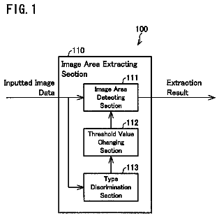
FIG. 1 is a block diagram illustrating an electrical configuration of a multifunction device including a CPU and an internal memory (RAM);
FIG. 2A is a view explaining how reference frame images are determined from a motion image file;
FIG. 2B is a view explaining how a representative frame image is selected in an extraction target range;
FIG. 3A is a view conceptually illustrating an input image information storage area of the RAM;
FIG. 3B is a view conceptually illustrating a motion image information storage area of the RAM;
FIG. 4A is a view conceptually illustrating a reference frame image information storage area of the RAM;
FIG. 4B is a view conceptually illustrating an extracted frame image information storage area of the RAM;
FIG. 5A is a view conceptually illustrating a layout image in which a plurality of frame images is laid out;
FIG. 5B is a view conceptually illustrating a frame difference information storage area of the RAM;
FIG. 6 is a flowchart of a media image printing process executed by the CPU of the multifunction device;
FIG. 7 is a flowchart of a print image selection process executed during the media image printing process of FIG. 6;
FIG. 8 is a flowchart of an output image generation process executed during the print image selection process of FIG. 7;
FIG. 9 is a flowchart of a representative frames selection process executed during the output image generation process of FIG. 8; and
FIG. 10 is a flowchart of a histogram generation process.
Detailed description
First, a general configuration of a multifunction device 10 (hereinafter referred to as "MFD 10") according to an embodiment of the present invention will be described with reference to FIG. 1.
The MFD 10 is provided with various functions, including a printer function, a scanner function, and a color copier function. As shown in FIG. 1, the MFD 10 is provided with a CPU 11, a ROM 12, an internal memory (RAM) 13, a scanning unit 14, a printing unit 15, an LCD unit 16, an input unit 17 and a media card slot 18 that are interconnected with one another by signal lines.
The CPU 11 performs all computations for the MFD 10. The ROM 12 is prestored with programs that the CPU 11 executes in order to implement processes (shown in FIGS. 6 to 9) described later. The RAM 13 temporarily stores results of computations performed by the CPU 11, inputted data, and the like. Details of the RAM 13 will be described later.
The printing unit 15 prints image data to which a print command has been issued. The printing unit 15 can print images in color using toner or ink of four colors: cyan, magenta, yellow and black.
The LCD unit 16 displays images (including images of character strings for messages) on a compact color liquid crystal display.
The input unit 17 has various operating keys that a user can press, and inputs data based on the pressed keys. More specifically, the input unit 17 includes an Up key, a Down key, a Left key, and a Right key for moving a cursor up, down, left, and right; and an OK key for accepting a selection (all keys are not shown).
The media card slot 18 receives a media card inserted thereinto, such as an SD card and a CompactFlash card (portable, non-volatile storage media). The MFD 10 also has a direct print function for directly reading image files from a media card inserted in the media card slot 18 and printing images represented by the image files.
The image files discussed herein include both still image files representing still images, and motion image files representing motion images and configured of a plurality of frame images. When the image file to be printed is a still image file, the MFD 10 generates the still image represented by the still image file on a single page. When the image file to be printed is a motion image file, the MFD 10 extracts a prescribed number (nine in the present embodiment) of frame images from the plurality of frame images constituting the motion image represented by the motion image file, and generates and prints an image having the extracted frame images laid out on a single page in an chronological order (to be referred to as a "layout image"; see FIG. 5A).
More specifically, as shown in FIG. 2A, the MFD 10 of the present embodiment first identifies nine frame images, including the first image (the first frame), the last image (the last frame), and seven images (seven frames) distributed equally therebetween, by dividing the total number of frames in the motion image file in eight equal intervals. The seven images may be obtained by dividing the total number of frames into eight approximately equal intervals if the total number of frames cannot be divided into exactly the same amounts of eight divisions. The extracted nine frame images are referred to as reference frame images REF(0)-REF
(serving as reference points). In other words, nine frame images that are positioned chronologically at a substantially equi-interval in a motion image file are selected as the reference frame images REF(0)-REF
in the present embodiment.
The MFD 10 further specifies, for each of the nine reference frame images REF(0)-REF
a range of frame images called "extraction target ranges ETR(0)-ETR(8)." Each extraction target range ETR(N) (where N=0-8) includes: a corresponding reference frame image REF(N); and a plurality of successive frame images that are chronologically continuous with the corresponding reference frame image REF(N) (to be referred to as "neighboring frame images"). The extraction target ranges are determined such that any two adjacent extraction target ranges ETR(N-1) and ETR(N) do not share any frame image in common with each other. In other words, any two adjacent extraction target ranges do not overlap with each other. Note that, as for the first extraction target range ETR(0), only those frame images that are positioned chronologically after the reference frame image REF
and that are continuous with the reference frame image REF
are selected as the neighboring frame images; as for the last extraction target range ETR(8), only those frame images that are positioned chronologically before the reference frame image REF
and that are continuous with the reference frame image REF
are selected as the neighboring frame images; and as for the remaining extraction target ranges ETR(1)-ETR(7), both of those frame images that are positioned chronologically before the respective reference frame images REF(1)-REF
and continuous with the reference frame images REF(1)-REF
and those frame images that are positioned chronologically after the respective reference frame images REF(1)-REF
and continuous with the reference frame images REF(1)-REF
are selected as the neighboring frame images.
From each extraction target range ETR(N) (where N=0-8), a single frame image is selected as a representative frame image REP(N) (where N=0-8), which is then actually laid out in a layout image (see FIG. 5A). More specifically, as shown in FIG. 2B, the MFD 10 calculates, for each extraction target range ETR(N) except for the first extraction target range ETR(0), a difference from the representative frame image REP(N-1) that has already been selected from an extraction target range ETR(N-1) which is positioned chronologically immediately before the extraction target range ETR(N) currently being processed. A frame image whose difference is the largest among all the frame images existing in the extraction target range ETR(N) is determined as a representative frame image REP(N) of the subject extraction target range ETR(N). In other words, as the representative frame image REP(N) of an extreaction target range ETR(N) (where N=1-8), the MFD 10 selects one frame image which has the largest difference from the representative frame image selected from the extraction target range ETR(N-1) among all the frame images in the extraction target range ETR(N). For the first extraction target range ETR
since there is no representative frame image REP(N-1) to be compared with, the first reference frame image REF
in the extraction target range ETR
(i.e., the first frame image) is determined as the representative frame image REP(0).
The MFD 10 displays a preview screen (not shown) on the LCD unit 16, enabling the user to select an image file to be printed from among the plurality of image files stored on the media card, and prints an image represented by the selected image file.
Next, storage areas of the RAM 13 will be described with reference to FIGS. 1 and 3A through 5B.
As shown in FIG. 1, the RAM 13 is provided with various storage areas for storing different types of data. The storage areas include an input image information storage area 31, a motion image information storage area 32, a reference frame image information storage area 33, a representative frame image information storage area 34, a frame difference information storage area 35, an output image data storage area 36, a preview image data storage area 37, a frame image data storage area 38, a print data storage area 39 and a temporary variable storage area 40.
The input image information storage area 31 serves to store information on image files stored on a media card inserted in the media cart slot 18. More specifically, as shown in FIG. 3A, the input image information storage area 31 is divided into an input image ID storage area 51, an input image filename storage area 52, and an input image file size storage area 53.
The input image ID storage area 51 serves to store IDs for image files stored on the media card. The IDs are assigned sequentially beginning from 0 based on the number of image files stored on the media card (hereinafter referred to as "input image IDs"). The input image IDs are assigned to the image files that have been read from the media card in such an order that the files have been read from the media card.
The input image filename storage area 52 serves to store filenames of the image files. Specifically, the input image filename storage area 52 is a 256-byte region, with each byte's worth of region being capable of storing data for one character or data for no character. The input image file size storage area 53 serves to store numerical values (values in units of kilobytes in this example) indicating the file sizes of the image files.
The motion image information storage area 32 serves to temporarily store information read from the media card for a motion image file being processed. Specifically, as shown in FIG. 3B, the motion image information storage area 32 is provided with a format type storage area 61, a codec type storage area 62, a horizontal size storage area 63, a vertical size storage area 64 and a total frame number storage area 65.
The format type storage area 61 stores data of a type of file format for the motion image file being processed. In the present embodiment, the format type storage area 61 may store one of the values 0, 1 and 2 that have been preassigned to one of three file formats: 0 for AVI format, 1 for MOV format and 2 for MPEG format.
The codec type storage area 62 stores data of a type of codec for the motion image file being processed. In the present embodiment, the codec type storage area 62 may store one of the values 0, 1 and 2 that have been preassigned to one of three types of codecs: 0 for MotionJPEG codec, 1 for MPEG1 codec and 2 for DivX codec.
The horizontal size storage area 63 stores numerical data indicating a number of pixels in a horizontal direction in each frame image constituting the motion image file (frame image) being processed.
The vertical size storage area 64 stores numerical data indicating a number of pixels in a vertical direction in each frame image constituting the motion image file (frame image) being processed.
The total frame number storage area 65 stores numerical data indicating a total number of frame images (number of frames) constituting the motion image file being processed.
The reference frame image information storage area 33 serves to store information on the reference frame images REF(0)-REF
Specifically, as shown in FIG. 4A, the reference frame image information storage area 33 is provided with a reference frame information control no. storage area 71, a reference frame no. storage area 72, an ETR starting frame no. storage area 73 and an ETR ending frame no. storage area 74.
The reference frame information control no. storage area 71 prestores one of the numbers 0 through 8 for controlling information on each of the nine reference frame images REF(0)-REF(8)(control no. (N), where N=0-8).
The reference frame no. storage area 72 serves to store numerical data indicative of where each reference frame image REF(N) is located within the motion image file, that is, frame no. of each, reference frame image REF(N), where N=0-8. The first frame of the motion image file is assigned with the frame no. of 0.
The ETR starting frame no. storage area 73 serves to store, for each control no. (N) (i.e., for each extraction target range ETR(N)), a frame no. that is the smallest among frame nos. of frame images existing in the extraction target range ETR(N) (to be referred to as "ETR starting frame no.").
The ETR ending frame no. storage area 74 serves to store, for each control no. (N) (i.e., for each extraction target range ETR(N)), a frame no. that is the largest among frame nos. of frame images existing in the extraction target range (to be referred to as "ETR ending frame no.").
The representative frame image information storage area 34 serves to store information on all the nine representative frame images REP(0)-REP(8). Specifically, as shown in FIG. 4B, the representative frame image information storage area 34 is provided with a representative frame information control ID storage area 81 and a representative frame no. storage area 82.
The representative frame information control ID storage area 81 prestores one of the numbers 0 through 8 for controlling information on each of the nine representative frame images REP(0)-REP
(control no. (N)). These numbers (control nos. (N) of 0-8) respectively correspond to numbers (0)-
preassinged to respective layout positions in the layout image shown in FIG. 5A.
The representative frame no. storage area 82 stores numerical data identifying where the representative frame images REP(0)-REP
are positioned within the motion image file (i.e., frame nos. of the representative frame images REP(0)-REP(8)).
The frame difference information storage area 35 serves to store a difference between a frame image in an extraction target range ETR(N) (N.sup.th extraction target range) and a representative frame image REP(N-1) that has already been selected from an extraction target range ETR(N-1) ((N-1).sup.th extraction target range or "previous extraction target range ETR(N-1)" that is positioned chronologically adjacent to and prior to the extraction target range ETR(N)). More specifically, as shown in FIG. 5B, the frame difference information storage area 35 is provided with a possible ETR frame number storage area 91, a frame difference storage area 92 and a corresponding frame no. storage area 93.
The possible ETR frame number storage area 91 serves to store numeral data indicating how many frame images will possibly be included in one extraction target range ETR(N) being processed (to be referred to as "possible ETR frame number"). As will be described later, how many frame images are indeed included in the extraction target range will be determined based on this possible ETR frame number, but may or may not be equal to the possible ETR frame number.
The frame difference storage area 92 serves to temporarily store a sum of differences in an absolute value between a frame image in the extraction target range ETR(N) and the representative frame image REP(N-1) selected from the previous extraction target range ETR(N-1) (to be referred to as "previous representative frame image REP(N-1)").
The corresponding frame no. storage area 93 serves to temporarily store numerical data indicating where a frame image, whose difference from the previous representative frame image REP(N-1) is stored in the frame difference storage area 92, is positioned within the motion image file (frame no.).
The output image data storage area 36 serves to temporarily store output image data (decoded image data representing a print image). For a motion image file, the output image is a layout image in which nine representative frame images REP(0)-REP
extracted from the motion image file are sequentially laid out at corresponding layout positions on a single page (see FIG. 5A). For a still image file, the output image is one still image, which is represented by the still image file, laid out on a single page.
The preview image data storage area 37 serves to temporarily store a preview image generated by converting (enlarging or reducing) the output image data stored in the output image data storage area 36 into a predetermined preview image size.
The frame image data storage, area 38 serves to temporarily store frame image data extracted from a motion image file being processed. Depending on the type of the motion image file, the frame image data is stored in a compressed state and in a format peculiar to the motion image file (JPEG format or MPEG format, for example).
The print data storage area 39 serves to temporarily store: intermediate process data on which a printing process is executed to generate print data (rasterized data); and the generated print data (rasterized data).
The temporary variable storage area 40 serves to temporarily store counters, such as a preview ID counter, a representative frame counter, a reference frame counter, a difference frame counter and a difference counter. These counters are used during various processes executed by the CPU 11, as will be described later.
Next, processes according to the present embodiment executed by the CPU 11 of the MFD 10 will be described in detail with reference to FIGS. 6 through 9.
The CPU 11 of the MFP 10 performs a media image printing process shown in FIG. 6. The media image printing process includes a print image selecting process (FIG. 7) during which an output image generating process (FIG. 8) is executed. The output image generating process further includes a representative frames selecting process (FIG. 9).
The CPU 11 executes the media image printing process of FIG. 6 when the user performs an operation on the input unit 17 to select a `media image printing mode` while a media card storing image files is inserted in the media card slot 18.
The media image printing process executed by the CPU 11 will be described while referring to a flowchart of FIG. 6.
In S101 at the beginning of this media image printing process, the CPU 11 executes a media information extraction process. Specifically, the CPU 11 reads information (a filename and a file size) for each image file stored in the media card, and stores the read information, sequentially in association with an input image ID indicative of the order that the image file has been read, in the input image filename storage area 52 and the input image file size storage area 53 of the input image information storage area 31. The input image IDs beginning from 0 are respectively stored in the input image ID storage area 51.
In S102 the CPU 11 executes the print image selecting process. During the print image selecting process, the CPU 11 displays at least one preview image on the LCD unit 16 to enable the user to capture how the image files stored on the media card will look like when actually printed, and prompts the user to select which image file should be actually printed.
The print image selecting process of S102 will be described with reference to a flowchart in FIG. 7.
In S201 at the beginning of the print image selecting process, the CPU 11 determines one image file to be displayed on the LCD unit 16 from among the image files stored in the media card. More specifically, the preview ID counter prestored in the temporary variable storage area 40 is given an initial value of 0. The CPU 11 determines the image file, whose input image ID (stored in the input image ID storage area 51) corresponds to the value of the preview ID counter, as a target image file whose preview image is to be displayed on the LCD unit 16. The preview image shown on the LCD unit 16 can be switched to another preview image of another image file in accordance with the user's operations of the Up, Down, Left and Right keys on the input unit 17, and one image file whose preview image is being displayed when the OK key is pressed is determined as a target image file to be printed.
In S202 the CPU 11 executes the output image generating process. During the output image generating process, the CPU 11 generates output image data (decoded print image data) for the image file determined in S201, and stores the output image data in the output image data storage area 36. The output image data is indicative of a layout image data shown in FIG. 5A if the selected image file is a motion image file. Whereas, if the selected image file is a still image file, the output image data is a still image represented by the still image file on a single page.
The output image generating process of S202 will be described with reference to a flowchart in FIG. 8.
In S301 at the beginning of the output image generating process, the CPU 11 reads (retrieves) the input image ID of the target image file whose preview image should be displayed on the LCD unit 16. More specifically, the CPU 11 refers to an input image ID that is equal to the current value of the preview ID counter and reads out the input image ID.
In S302 the CPU 11 then determines whether the type of the target image file determined in S301 is classified as a still image file or a motion image file by referencing header data in the target image file. Specifically, the CPU 11 refers to the filename stored in the input image filename storage area 52 in association with the input image ID of the target image file in the input image information storage area 31. By using the filename, the CPU 11 directly accesses the target image file stored on the media card and refers to the header data therein.
If the CPU 11 determines in S302 that the image file is a motion image file, in S303 the CPU 11 executes a process to extract motion image parameters from the motion image file. In this process, the CPU 11 acquires format type data, codec type data, horizontal size data, vertical size data and total frame number data for the motion image file. The CPU 11 stores these data respectively in the format type storage area 61, codec type storage area 62, horizontal size storage area 63, vertical size storage area 64 and the total frame number storage area 65 of the motion image information storage area 32 (see FIG. 3B). If data for a different motion image file has already been stored in the motion image information storage area 32 at this time, the CPU 11 first deletes the existing data before storing the data for the motion image file currently being processed (overwrites the existing data).
In S304 the CPU 11 executes the representative frames selecting process. During the representative frames selecting process, the CPU 11 selects nine representative frame images REP(0)-REP
from among the frame images in the motion image file. The nine representative frame images REP(0)-REP
are assigned with control nos. (N) beginning from 0 to 8, and the frame nos. of the respective representative frame images REP(0)-REP
are stored in the representative frame no. storage area 82 of the representative frame image information storage area 34 in association with the control nos. (see FIG. 4B). Details of the extracted frame selecting process will be described later with reference to FIG. 9.
The CPU 11 executes (repeats) processing of S305-S309 sequentially to layout the nine representative frame images REP(0)-REP
selected in S304 onto a layout image.
Specifically, before the loop of S305-S309 is executed for the first time, the representative frame counter prestored in the temporary variable storage area 40 is given an initial value of 0. The CPU 11 executes the processing of S305-S309 sequentially on the representative frame image REP(N) whose control no. (N) is in coincidence with the current value (N) of the representative frame counter. Once the processing of S309 ends (S309: NO), the CPU 11 increments the value of the representative frame counter by one
to (N+1) and returns to S305 to execute the processing of S305-S309 on the next one of the remaining representative frame images REP(N+1).
More specifically, in S305 the CPU 11 executes a process to extract, from the motion image file, frame image data whose frame no. is the same as the frame no. of the representative frame image stored in the representative frame no. storage area 82. That is, the CPU 11 extracts frame image data for the representative frame image REP(N) whose control no. (N) is equal to the current value (N) of the representative frame counter.
In S306 the CPU 11 stores the frame image data extracted in S305 (in a compressed state) in the frame image data storage area 38.
In S307 the CPU 11 performs an expansion (decoding) process on the frame image data stored in the frame image data storage area 38 and converts the frame image data into a format in which pixel calculations are possible (such as image data expressing RGB values for each pixel as numerical values from 0 to 255).
In S308 the CPU 11 lays out and stores the decoded frame image data in the output image data storage area 36 at a layout position whose layout position no. corresponds to the current value (N) of the representative frame counter.
In S309 the CPU 11 determines whether all the nine representative frame images REP(0)-REP
(having control nos. of 0-8) have been laid out in the output image data storage area 36. Specifically, the CPU 11 determines that all the representative frame images have been laid out in the output image data storage area 36 when the value of the representative frame counter reaches 8.
When determining that there still remains a representative frame image to be laid out in the output image data storage area 36 (S309: NO), the CPU 11 increments the representative frame counter by one
and returns to S305 for performing the processing of S305-S309 on data for the next representative frame image.
When all the data of the representative frame images is determined to have been laid out in the output image data storage area 36 (S309: YES), the CPU 11 ends the output image generating process. At this time, the image data stored in the output image data storage area 36 (i.e., layout image) is the output image data for the motion image file.
On the other hand, if the CPU 11 determines in S302 that the target image file is a still image file, in S310 the CPU 11 performs an expansion (decoding) process on the still image file to convert the image data in the still image file to a format in which pixel calculations are possible.
In S311 the CPU 11 stores the image data expanded in S310 in the output image data storage area 36, and subsequently ends the current output image generating process. In other words, for a still image file, unlike a motion image file, a single still image is laid out in the output image data storage area 36. At this time, the image data stored in the output image data storage area 36 (pixel data representing a still image) is the output image data for the still image file.
Upon completion of the output image generating process, the CPU 11 proceeds to S203 of the print image selecting process (FIG. 7).
In S203 the CPU 11 enlarges or reduces the output image data into a predetermined size of the preview image (a fixed size of 160.times.120 pixels in the present embodiment) using the well-known nearest-neighbor method, and stores the enlarged/reduced data (preview image data) in the preview image data storage area 37.
In S204 the CPU 11 displays, on the input unit 17, an image (preview image) represented by the preview image data stored in the preview image data storage area 37.
In S205 the CPU 11 accepts input from the input unit 17 in accordance with the user's operation of the keys. In S206 the CPU 11 determines whether the pressed key is the OK key or another key, such as the Up key, Down key, Left key or Right key.
When the pressed key is a key other than the OK key, the CPU 11 proceeds to S207 where the value of the preview ID counter is updated.
More specifically, when the pressed key was the Down key or Right key, in S207 the CPU 11 increments the preview ID counter by one
in order to switch the preview image of the image file currently being displayed to another preview image of an image file whose input image ID is greater by one
than that of the image file whose preview image is currently being displayed. On the other hand, if either the Up key or Left key was pressed, in S207 the CPU 11 decrements the preview ID counter by one
in order to switch the preview image of the image file currently being displayed to another preview image of an image file whose input image ID is smaller by one
than that of the image file whose preview image is currently being displayed. In this way, the preview image currently being displayed on the LCD unit 16 is changed into another preview image representing another image file. The CPU 11 then returns to S201.
However, if the value of the preview ID counter is to exceed "the number of the image files stored on the media card -1" as a result of the above increment or decrement, the CPU 11 maintains the value of the preview ID counter without performing any calculation. At this time, the preview image shown on the LCD unit 16 does not change. Here, the CPU 11 may return to S205 instead of S201.
If the CPU 11' determines the OK key was pressed in S206, which means that the preview image currently being displayed on the LCD unit 16 is selected as the image file to be printed (print target), the CPU 11 terminates the print image selecting process of S102 and proceeds to the S103 of the media image printing process (FIG. 6).
In S103, the CPU 11 executes an image printing process to print the output image for the image file selected in S102. In the image printing process, the CPU 11 copies, line by line, the output image data that is now stored in the output image data storage area 36 to the print data storage area 39, executes color conversion (from RGB to CMYK) and binary conversion on the copied output image data, and outputs the converted output data to the printing unit 15. The printing unit 15 then performs printing based on the binary data. The CPU 11 subsequently terminates the media image printing process.
Next, the representative frames selecting process of S304 will be described with reference to a flowchart in FIG. 9. During this process, nine representative frame images are selected from among the frame images in the target motion image file to be actually laid out in the layout image of the motion image represented by the motion image file.
In S401 at the beginning of the representative frames selecting process, the CPU 11 calculates how may frame images should be included in each extraction target range ETR(N) in the target motion image file (possible ETR frame number). In the present embodiment, the possible ETR frame number is set to be equal to a sum of 1 (number of the reference frame image) and a value of FPS (Frames Per Second) for the target motion image file. The FPS indicates how many number of frame images are played back per one second in the motion image file. In other words, the possible ETR frame number is set such that the number of neighboring frame images existing in each extraction target range (i.e., the number of frame images belonging to the extraction target range ETR(N) excluding the reference frame image REF(N)) is identical to the number of frame images played back per one second (FPS).
In S402 the CPU 11 stores the possible ETR frame number (i.e., FPS+1) calculated in S401 in the possible ETR frame number storage area 91 of the frame difference information storage area 35 (see FIG. 5B in which the value of 31 is stored as the possible ETR frame number as an example).
In S403 the CPU 11 calculates frame nos. of the nine reference frame images REF(0)-REF
(to be referred to as "reference frame no."). In the present embodiment, the nine reference frame images REF(0)-REF
are selected to include: the first frame image, the last frame image and seven frame images distributed equally therebetween, the seven frame images being derived by dividing the total number of frames in the motion image file in eight equal intervals. More specifically, frame images that are positioned at every such a number of frame images in the motion image file are selected as the reference frame images REF(0)-REF(8), the number being equal to a value that is obtained by dividing "the total number of frame images -1" by "the number of frame images to be extracted -1 (9-1=8 in the present embodiment)." In case that the value obtained by dividing "the total number of frame images -1" by "the number of frame images to be extracted -1" is not an integer, an integer close to the derived value, (for example, an integer that is obtained by rounding down the derived value after the decimal point) may be set as the number for determining the reference frame images.
In S404 the CPU 11 stores the reference frame nos. calculated in S403 in the reference frame no. storage area 72 of the reference frame image information storage area 33 (FIG. 4A). Specifically, the reference frame nos. are stored sequentially in correspondence with the control nos. (N) (N=0-8) of the reference frame information control no. storage area 71 (FIG. 4A) such that the smaller reference frame nos. are stored in sub-regions of the reference frame no. storage area 72 assigned with the smaller control nos. (N).
In S405 the CPU 11 derives, for each of the nine reference frame images REF(0)-REF(8), the ETR starting frame no. (smallest frame no. in the corresponding extraction target range) and the ETR ending frame no. (greatest frame no. in the corresponding extraction target range), by executing the following procedures [1] and [2].
[1] Calculation of the ETR Starting Frame No.
The description continues in the full USPTO document.
 Lapsed, fee not paid5 drawings