Lapsed, fee not paid6 drawings
Cameras, Displays & Optics · US 8,633,446 B2
X-ray detector and X-ray image detecting method
An X-ray detector and a method of detecting an X-ray image.
US 8,633,644 B2 · Assignee: Sharp Kabushiki Kaisha · Inventors: Yamamoto; Emi et al.
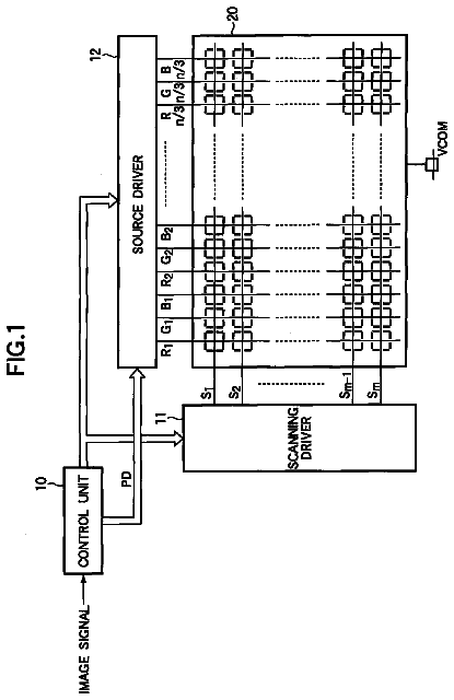
Sheet 1 of 5 from the published document. All sheets in the USPTO PDF
The present invention provides a thin-film formed substrate, an organic electroluminescent display device, a color filter substrate, and a method of producing a thin-film formed substrate. The thin-film formed substrate according to the present invention is a thin-film formed substrate provided with a substrate and a thin film formed on the substrate, the substrate comprising a first bank forming a depression on the substrate, and a second bank formed on the first bank, wherein a partitioned region surrounded by the second bank has a plurality of the depressions arranged therein, and the thin film is arranged in each of the depressions.
Film production technologies are frequently used in production of displays such as formation of semiconductive layers. Particularly the film production technology using an ink jet device (ink jet method) is employed in production of organic EL layers for organic EL elements, color filter layers for color filter substrates, and functional thin films such as pattern wirings for metal wiring substrates. The ink jet method makes it possible to easily adjust the thickness of thin films and easily respond to enlargement of the area compared to solid phase methods such as deposition. Further, the ink jet method provides high material efficiency, and thus makes it possible to reduce the cost. Generally in the ink jet method, a functional fluid containing a functional material (thin film material) and a solvent is applied and then the solvent is removed to leave a functional thin film. If the sol
1 of 5 drawing sheets so far from the published document, cropped to the drawing. Every sheet is in the USPTO PDF.
What the patent claimed, word for word. All of it is now free to use.
This application is the U.S. national phase of International Application No. PCT/JP2009/058852, filed 12 May 2009, which designated the U.S. and claims priority to Japanese Patent Application No. 2008-240881, filed 19 Sep. 2008, the entire contents of each of which are hereby incorporated by reference.
The present invention relates to a thin-film formed substrate, an organic electroluminescent (hereinafter also referred to as organic EL) display device, a color filter substrate, and a method of producing a thin-film formed substrate. More specifically, the present invention relates to a thin-film formed substrate, an organic EL display device, a color filter substrate, and a method of producing a thin-film formed substrate which enable suitable use of a coater such as an ink jet device in production.
Film production technologies are frequently used in production of displays such as formation of semiconductive layers. Particularly the film production technology using an ink jet device (ink jet method) is employed in production of organic EL layers for organic EL elements, color filter layers for color filter substrates, and functional thin films such as pattern wirings for metal wiring substrates. The ink jet method makes it possible to easily adjust the thickness of thin films and easily respond to enlargement of the area compared to solid phase methods such as deposition. Further, the ink jet method provides high material efficiency, and thus makes it possible to reduce the cost.
Generally in the ink jet method, a functional fluid containing a functional material (thin film material) and a solvent is applied and then the solvent is removed to leave a functional thin film. If the solvent volatilizes at the head portion and thereby a functional material or the like is precipitated during ejection of the printing liquid droplets, ejection defects may occur such as that the droplets maybe ejected onto different positions or the amounts of ejected droplets may be different. Further, depending on the differences in the ejection accuracy or the ejection amount of the nozzles of the ink jet device, functional thin films having desired film thicknesses may not be achieved or the film thicknesses of the functional thin films may be different.
The ink jet method thus usually employs a process of applying a functional fluid to regions partitioned by portions called banks. For example, Patent Document 1, discloses a technology of filling a functional fluid in the regions partitioned by banks and forming patterned wirings. This technology requires the banks to be formed corresponding to the wiring patterns, and thus still has room for improvement in that it is difficult to form, with this technology, complicated wiring patterns or high resolution devices. Meanwhile, Patent Documents 2, and 3, each disclose a technology of stacking lyophilic bank and a lyophobic bank. As for this technology, there is room for improvement in that when a surface treatment is performed on the bank stacked on the upper side, the effect of the bank arranged thereunder is negated, and thus sufficient effects cannot be provided. Patent Document 4, discloses an organic EL display device in which an organic EL layer is formed in a region partitioned by stacked lyophilic first bank and a lyophobic second bank. In this technology, there is room for improvement in that an electron injection transport layer cannot be completely covered by a middle layer and a light-emitting layer, which are to be applied on the electron injection transport layer, because the electron injection transport layer is attached on the wall surface of the banks or on the banks, and the incomplete covering causes a direct contact between the electron injection transport layer and the cathode, whereby the functions of the organic EL layer decrease. [Patent Document 1] Japanese Kokai Publication No. 2007-95729 [Patent Document 2] Japanese Kokai Publication No. 2007-280866 [Patent Document 3] Japanese Kokai Publication No. 2008-4376 [Patent Document 4] Japanese Kokai Publication No. 2005-326799
Hereinafter, the problems in conventional substrates having a thin film will be described with an example of an organic EL element.
An organic EL element has a structure in which an organic EL layer including at least a light-emitting layer is sandwiched by an anode and a cathode, and is arranged in a pixel region surrounded by a bank. Further, an organic EL element usually has organic layers such as an electron injection layer, a carrier transport layer (an electron transport layer, a hole transport layer), and a hole injection layer as well as a light-emitting layer. A carrier transport layer is usually designed to have lower resistance and a higher conductivity than a light-emitting layer in order to allow a sufficient electric field to be applied to the light-emitting layer. Further, in order to prevent carriers from passing through the light-emitting layer without contributing to light emission, a carrier blocking layer, which is a functional material layer for capturing the carriers within the light-emitting layer, may be formed between the carrier transport layer and the light-emitting layer. Such a carrier blocking layer usually has low conductivity, and therefore has a much smaller thickness than the light-emitting layer in many cases. Since an organic EL element is formed by laminating thin films (organic EL layers) in the above way, it has been particularly difficult for such an organic EL element to have uniformly controlled film thicknesses as compared to color filter substrates and wiring substrates.
Now, a case will be described in which a hole transport layer and a light-emitting layer are sequentially laminated by applying functional fluids to each pixel region surrounded by a bank by the ink jet method. Here, anodes are already formed in the pixel regions. First, a functional fluid containing a hole injection material and a solvent is ejected on each anode and then the solvent is removed by drying and heating so that a hole transport layer is formed on the anode. Subsequently, a functional fluid containing a light-emitting material and a solvent is ejected onto the hole transport layer. At this time, the functional fluid may not be sufficiently maintained within the region surrounded by the bank depending on the shape of the bank and, as a result, the functional fluid may not completely cover the hole transport layer and the anode. In this case, a part of the anode and the hole transport layer turns out to be exposed. If a cathode is formed on the light-emitting layer in this state by a method such as a vacuum deposition, the cathode comes in contact with the hole transport layer and the anode directly without the light-emitting layer interposed therebetween, at the portions where the hole transport layer and the anode are exposed. At those contact portions, carriers cannot contribute to light emission in the case that light is emitted by application of electric current to the organic EL element, and thereby the electric current utilization efficiency decreases. The decrease causes problems such as a decrease in brightness, generation of heat, and an increase in power consumption, which lead to major problems in the power efficiency or the element life. The hole transport layer and the anode are therefore preferably completely covered by the light-emitting layer. The above problems similarly arise in a structure in which an electron transport layer is arranged between the cathode and the light-emitting layer, when there is contact, without the light-emitting layer interposed, between the anode and the cathode, between the hole transport layer and the electron transport layer, between the hole transport layer and the cathode, or between the electron transport layer and the anode.
In a structure in which each of the pixels is enclosed (partitioned) by the bank parts, a functional fluid is to be ejected in the respective pixels and maintained in the respective pixels. Here, since nozzles may eject droplets in different amounts because of the different nozzle sizes generated in the production, and thereby the amount of a functional fluid to be applied can be different from pixel to pixel. Also, when the position onto which a functional fluid droplet is ejected happens to be displaced and the functional fluid accordingly enters an adjacent pixel, the amounts of the functional fluid can be different in the respective pixels. As a result, the organic EL layers can have different thicknesses for the respective pixels, and the difference appears as display unevenness.
Those problems cannot be solved even by the technologies of Patent Documents 2, to 4.
The present invention has been made in view of the above state of the art, and aims to provide a thin-film formed substrate which can easily achieve improvement in thin-film flatness and a yield rate; an organic electroluminescent display device; a color filter substrate; and a method of producing a thin-film formed substrate.
Means for Solving the Problems
The present inventions have made various studied on thin-film formed substrates which can easily achieve improvement in thin-film evenness and a yield rate without an additional complicated production process. As a result, the inventors have focused on use of two kinds of banks. More specifically, a first bank forming depressions is arranged on the substrate and then a second bank is arranged on the first bank in such a manner as to surround the depressions. This arrangement has been found to enable application of a functional fluid in a region (partitioned region) surrounded by the second bank to form a flat thin film within each depression. Further, the arrangement can increase the margins of the alignment accuracy and the droplet placement accuracy of the thin film formation device and thus improve the yield of thin-film formed substrates. In this way, the above problems have been solved admirably and thereby the present invention has been completed.
That is, one aspect of the present invention is a thin-film formed substrate provided with a substrate and a thin film formed on the substrate, the thin-film formed substrate comprising a first bank forming a depression on the substrate, and a second bank formed on the first bank, wherein a partitioned region surrounded by the second bank has a plurality of the depressions arranged therein, and the thin film is arranged in each of the depressions. On the thin-film formed substrate according to the present invention, one first bank may form any number of depressions; that is, a first bank may form multiple depressions or a single depression. In the case that one first bank forms a single depression, multiple first banks may be provided.
When a functional fluid is applied to a region (partitioned region) surrounded by the second bank on the thin-film formed substrate according to the present invention, the functional fluid spreads along side faces of the second bank in such a manner as to cover the depressions. As a result, the fluid level of the functional fluid in the respective depressions can be suitably equilibrated. Also, since the first bank maintains (pins) the functional fluid within the depressions, the functional fluid is enclosed within the depressions in a process of removing the solvent. In the above manner, a flat thin film can be formed at a desired position (depression).
The thin-film formed substrate according to the present invention can also increase the margins of the alignment accuracy and the droplet placement accuracy of a thin-film formation device in the case of including the first bank and the second bank in a stacked manner as compared to the case of including the first bank only. Thereby, defects in a thin-film formation process (for example, thickness variation of thin films) can be suppressed, and the yield of thin-film formed substrates can be improved.
A thin film herein refers to a film which has a thickness suitable for a component such as an organic EL layer of an organic EL element and a color filter of a color filter substrate. More specifically, the thin film may have a thickness of 0.01, to 3 .mu.m. First and second banks herein each refer to a partition wall placed in a frame-like arrangement (a frame-like object).
The structure of the thin-film formed substrate according to the present invention is not particularly limited as long as the thin-film formed substrate includes the above components, and may or may not include other components.
Preferable embodiments of the thin-film formed substrate according to the present invention are described in detail below. Note that the various embodiments below may be appropriately combined.
The partitioned region preferably has a linear planar shape. Such a shape allows a functional fluid applied to a partitioned region to spread along the side faces of the second bank more easily due to the capillary effect. As a result, the fluid level of the functional fluid in the respective depressions can be suitably equilibrated.
In the case that the entire second bank is lyophobic to a functional fluid, it may be difficult for the functional fluid to spread along the side faces of the second bank. In contrast, in the case that the entire second bank is lyophilic to a functional fluid, the functional fluid may flow over the top face of the second bank to flow into a region where no functional fluid is required. Accordingly, the second bank is preferably lyophobic to a functional fluid on a top face, and the second bank is preferably lyophilic to a functional fluid on a side face. Such a structure can be achieved for example by performing a lyophobicity providing process on the second bank formed from a lyophilic material. However, in the case that a lyophobicity providing process is performed on the second bank having a forward-tapered shape, the side faces of the second bank may also be lyophobic. As a result, it may be difficult for a functional fluid to spread along the side faces of the second bank. Hence, the second bank preferably has a reverse-tapered shape. The reverse-tapered shape allows the side faces of the second bank to go into the shadow of the top face of the second bank, and thus reduces the influence of the lyophobicity providing process on the side faces of the second bank. As a result, the second bank can easily have lyophobic top face and lyophilic side faces.
The "top" herein refers to a position farther from the substrate, and the "bottom" herein refers to a position closer to the substrate. Further, the "reverse-tapered shape" herein refers to a shape with an angle of a side face to the substrate face (i.e., taper angle) of 90.degree. or larger, and the "forward-tapered shape" herein refers to a shape with an angle of a side face to the substrate face of smaller than 90.degree..
One of the conditions for decreasing the influence of the lyophobicity providing process on the side faces of the second bank is that the side faces of the second bank do not project from the top face of the second bank in a plan view. That is, it is preferable that the partitioned region have a linear planar shape, and a length L1 of a bottom face of the partitioned region, in a cross-sectional view of the substrate in a short-side direction of the partitioned region, and a length L2 of a top face of the partitioned region satisfy the relation L1.gtoreq.L2, and more preferably the relation L1>L2.
If the first bank has a reverse-tapered shape, it may be possible that a functional fluid collects between the substrate and the side faces of the first bank and cannot fully spread within the partitioned region. In such a state, it may be difficult to produce a flat thin film within a depression. Accordingly, the first bank preferably has a forward-tapered shape.
The first bank preferably has a forward-tapered shape, and the second bank preferably has a reverse-tapered shape. Thereby, a functional fluid can be suppressed from collecting between the substrate and the side faces of the first bank, and the influence of the lyophobicity providing process on the side faces of the second bank can be decreased.
The first bank is preferably provided with fluorine on an upper face where the second bank is not arranged. When being provided with fluorine, the first bank can be lyophobic to a functional fluid on the upper face where the second bank is not arranged. As a result, the functional fluid can be more surely maintained (pinned) in a depression, and a flat thin film can be more surely produced. Here, the upper face of the first bank encompasses not only the top face of the first bank but also the side faces of the first bank.
The second bank is preferably provided with fluorine on a top face. When being provided with fluorine, the second bank can be lyophobic to a functional fluid on the top face. As a result, the functional fluid can be more surely enclosed within a partitioned region, and can be more surely prevented from flowing over the top face of the second bank into a region where no functional fluid is required.
The first bank is preferably provided with fluorine on an upper face where the second bank is not arranged, and the second bank is preferably provided with fluorine on a top face. When being provided with fluorine, the first bank can be lyophobic to a functional fluid on the upper face where the second bank is not arranged, and the second bank can be lyophobic to a functional fluid on the upper face. As a result, a flat thin film can be more surely produced within a depression, and the functional fluid can be more surely prevented from flowing over the top face of the second bank into a region where no functional fluid is required. Such a structure, in which the first bank is provided with fluorine on the upper face where the second bank is not arranged and the second bank is provided with fluorine on the top face, can be produced for example by performing, at one time, a fluorine plasma process on the upper face of the first bank where the second bank is not arranged and on the top face of the second bank. Accordingly, the production process can be simplified.
The method of achieving the structure, in which the upper face of the first bank where the second bank is not arranged and/or the top face of the second bank is/are provided with fluorine, may be, alternatively to the above fluorine plasma process, a method of coating the face(s) with a film that contains fluorine.
A distance h1 from the surface of the substrate to a top face of the second bank preferably satisfies the relation h1>65, .mu.m. Such a structure prevents generation of a void portion where no thin film exists on the substrate inside partitioned regions.
If an end of the bottom face of a depression is not 15 .mu.m or farther away from an end of the bottom face of a partitioned region in a plan view, a part of the functional fluid maintained within a depression may be attached to a side face of the second bank, and thereby the uniformity of the thicknesses of the thin films formed within the depressions may be decreased. Accordingly, an end of a bottom face of each depression is preferably 15, .mu.m or farther away from an end of a bottom face of the partitioned region.
It is preferable that the partitioned region have a linear planar shape, the thin-film formed substrate have a first object formed on the first bank, and the first object be in contact with the second bank, and have a planar shape projecting from the second bank toward between the depressions arranged in the partitioned region. This structure enables to prevent excess flow of a functional fluid due to the capillary effect. Further, since the second bank has a similar (analogous) structure to the first bank, the drying speeds of the functional fluid can be made uniform within a partitioned region. With the above structure, it is possible to produce flatter thin films in the depressions.
The first object may be produced from a different material from the second bank, but still is preferably produced from the same material as the second bank. In this case, the first object and the second bank can be formed in the same process, and thus the production process can be simplified. Alternatively, the first object and the second bank may be integrally formed. That is, the second bank may have a projection which functions as the first object.
It is preferable that the partitioned region have a linear planar shape, the thin-film formed substrate have a second object formed on the first bank, and the second object be arranged between the depressions arranged in the partitioned region, and be not in contact with the second bank. The same effect as in the case with the first object can also be achieved in this case.
The second object may be produced from a different material from the second bank, but still is preferably produced from the same material as the second bank. In this case, the second object and the second bank can be formed in the same process, and thus the production process can be simplified.
Another aspect of the present invention is a method of producing the thin-film formed substrate of the present invention, the method comprising: a first bank formation process of forming the first bank on the substrate; a second bank formation process of forming the second bank on the first bank; and an application process of applying a functional fluid containing a thin film material to the partitioned region.
In accordance with the method of producing the thin-film formed substrate of the present invention, when a functional fluid is applied to a partitioned region, the functional fluid spreads along the side faces of the second bank in such a manner as to cover the depressions. As a result, fluid level of the functional fluid in the respective depressions can be suitably equilibrated. Further, since the first bank maintains (pins) the functional fluid within each depression, the functional fluid is enclosed within the depression in a process of removing the solvent. In the above manner, a flat thin film can be formed at a desired position (depression).
The method of producing the thin-film formed substrate of the present invention can also increase the margins of the alignment accuracy and the droplet placement accuracy of a coater in the case of including the first bank and the second bank in a stacked manner as compared to the case of including the first bank only. Thereby, defects in a thin-film formation process (for example, thickness variation of thin films) can be suppressed, and the yield of thin-film formed substrates can be improved.
The method of producing the thin-film formed substrate of the present invention is not particularly limited by other processes as long as including the above process.
A preferable method of producing the thin-film formed substrate of the present invention is explained in detail below. Note that the various embodiments below may be appropriately combined.
The first bank is preferably lyophobic to a functional fluid on an upper face where the second bank is not arranged. This makes it possible to more surely maintain (pin) a functional fluid within a depression, and thus to more surely produce a flat thin film within the depression.
The second bank is preferably lyophobic to a functional fluid on a top face. As a result, a functional fluid can be more surely maintained within a partitioned region, and can be more surely prevented from flowing over the top face of the second bank into a region where no functional fluid is required.
The first bank is preferably lyophobic to a functional fluid on an upper face where the second bank is not arranged, and the second bank is preferably lyophobic to a functional fluid on a top face. As a result, a flat thin film can be more surely produced within a depression, and the functional fluid can be more surely prevented from flowing over the top face of the second bank into a region where no functional fluid is required. Such a structure, in which the first bank is lyophobic on the upper face where the second bank is not arranged and the second bank is lyophobic on the top face, can be produced by performing, at one time, a lyophobicity providing process on the upper face of the first bank where the second bank is not arranged and on the top face of the second bank. Accordingly, the production process can be simplified.
The second bank is preferably lyophilic to a functional fluid on a side face. With this structure, the functional fluid spreads along the side faces of the second bank more easily, and thus a flatter thin film can be produced.
The functional fluid applied to a partitioned region spreads within the partitioned region along the side faces of the second bank that face each other, and the fluid surface of the functional fluid reaches the ends of the top face of the second bank. At this time, the fluid surface of the applied functional fluid is lower at a position farther from the second bank. If the fluid surfaces of the functional fluid flowing along the opposite side faces of the second bank respectively reach the surface of the substrate without coming into contact with each other, a void portion is generated in which no functional fluid exists on the substrate within the partitioned region, and thereby no thin film will be formed in the void portion. Therefore, in order to surely prevent generation of such a void portion, the second bank may be designed to have an appropriate height that does not generate a void portion.
Now, the condition for not generating a void portion, in which no functional fluid exists on the substrate in a region sandwiched by the second bank parts, will be described with reference to a drawing. FIG. 6 is a cross-sectional view schematically illustrating the state where the functional fluid is applied in the region sandwiched by the second bank parts. Note that the first bank is not illustrated in FIG. 6. As illustrated in FIG. 6, h1 represents a distance from the surface of a substrate 110 to the top face of a second bank 112; .alpha. represents a taper angle of the second bank 112 to the substrate 110 (an angle of gradient of a side face of the second bank 112 in a cross section); .theta. represents an angle of contact of a functional fluid 130 to a side face of the second bank 112; .epsilon. represents a crossing point of lines drawn at an angle of .theta. from the ends of the top face of the second bank 112; y represents a distance from an end of the top face of the second bank 112 to .epsilon. in a plan view; d represents a length of the bottom face between the opposite parts of the second bank 112 (the length of the bottom face in the partitioned region); h2 represents a height difference between the top face of the second bank 112 and .epsilon.; and x represents a height difference between .epsilon. and the substrate 110. With those representations, the second bank 112 may be designed to always have a height that satisfies the relation x>0. The condition for satisfying the relation x>0, can be led by the following formulas
to (3).
.times..times..times..times..alpha..times..times..function..alpha..theta.- .times..times..times..times..alpha..times..function..alpha..theta..times..- times..times..times..times..times..times..times..times..times..alpha..time- s..function..alpha..theta.> ##EQU00001##
The condition led by the formulas
to
is shown by the following formula (4). Therefore, in order to satisfy the relation x>0,, the second bank may be designed to have a height that satisfies the following formula (4). That is, it is preferable that the partitioned region have a linear planar shape, and the application process comprise applying a functional fluid such that the distance h1 from the surface of the substrate to a top face of the second bank satisfy the following formula (4), when the substrate is observed in a cross section in a short-side direction of the partitioned region in a portion that passes through any of the depressions arranged in the partitioned region, wherein d represents a length of the bottom face of the partitioned region, .alpha. represents a taper angle of the second bank to the substrate, and .theta. represents an angle of contact of the functional fluid to a side face of the second bank.
>.function..alpha..theta..function..alpha..times..function..alpha..the- ta. ##EQU00002##
In the above formula (4), a relation h1>65, .mu.m is preferably satisfied. Since the suitable value of d is different according to the application of the thin-film formed substrate, the formula
may not be satisfied depending on the value of d. For example, in the case that the thin-film formed substrate of the present invention is used for a display, the pixel size is determined according to the required fineness, and thereby the range for d can be specified. When the values of .alpha. and .theta. are constant, a change in the value of d leads to a change in the right side of the formula (4). For this reason, the formula
may not be satisfied depending on the value of d. In contrast, the formula
can be surely satisfied with the range of d of 50 to 100, .mu.m when the relation h1>65, .mu.m is satisfied. When .theta. and .alpha. are set to be easily achieved values (.theta. is 45.degree. or larger, .alpha. is 70.degree. to 120.degree.) in the case that the second bank is formed from a common material by a common method, the value of the right side of the formula
will not exceed 65, .mu.m even if d is changed within the range of 50, to 100, .mu.m. Therefore, the formula
can be satisfied in the range of d of 50, to 100, .mu.m when the relation h1>65, .mu.m is satisfied. In the formula (4), the larger the value of .theta., the smaller the value of the right side of the formula. Here, the value of d may be 50, .mu.m or less. Still, in terms of securement of the application margin in the case of using the ink jet method or the like, the relation d>50, .mu.m is preferably satisfied.
If the relations 0.degree.<.alpha.-.theta.<90.degree. and .alpha.>90.degree. are satisfied, the term cot(.alpha.)tan(.alpha.-.theta.) will be a negative value which is very small as compared to the term tan(.alpha.-.theta.). Thereby, the denominator of the right side of the formula
will be a positive value of approximately 1. The above h1 therefore can be represented simply by the following formula (5). That is, if the relations 0.degree.<.alpha.-.theta.<90.degree. and .alpha.>90.degree. are satisfied in the formula (4), the above h1 preferably satisfies the following formula (5).
.times..times.>.function..alpha..theta. ##EQU00003##
If the relation .alpha.=90.degree. is satisfied, then the term cot(90.degree.) may be regarded as 0, and the relation of the following formula
may satisfied.
.function..times..degree..theta..function..times..degree..theta..function- ..times..degree..theta..function..theta..function..theta..function..theta. ##EQU00004##
Therefore, the above h1 can be simply represented by the following formula (7). That is, when .alpha.=90.degree. in the above formula (4), the above h1 preferably satisfies the following formula (7).
.times..times.>.function..theta. ##EQU00005##
Another aspect of the present invention is an organic EL display device comprising the thin-film formed substrate of the present invention or a thin-film formed substrate produced by the production method of the present invention, wherein the organic EL display device has a first electrode and a second electrode which sandwich the thin film, and the thin film is an organic EL layer. With this structure, since a flat organic EL layer can be produced in a depression, an organic EL display device with little display unevenness can be produced. Further, since the coatability of the organic EL layer can be improved, generation of the leakage current resulting from the short circuit of the first and second electrodes can be suppressed.
Yet another aspect of the present invention is also a color filter substrate comprising the thin-film formed substrate of the present invention or a thin-film formed substrate produced by the production method of the present invention, wherein the thin film is a color filter. With this structure, a color filter substrate having a flat color filter can be produced. Further, use of the color filter substrate of the present invention for a liquid crystal display device enables production of a liquid crystal display device with little display unevenness. In this way, the color filter substrate of the present invention can be suitably used especially for a liquid crystal display device.
Effect of the Invention
The thin-film formed substrate, the organic EL display device, the color filter substrate, and the method of producing a thin-film formed substrate of the present invention enable production of a thin-film formed substrate which can easily achieve improvement in thin-film flatness and a yield rate; an organic electroluminescent display device; a color filter substrate; and a method of producing a thin-film formed substrate.
FIG. 1 is a plan view schematically illustrating an organic EL display device of Example 1.
FIG. 2 is a cross-sectional view schematically illustrating the organic EL display device on an X1-Y1 line in FIG. 1 before formation of organic EL layers.
FIG. 3 is a cross-sectional view schematically illustrating the organic EL display device on an X2-Y2 line in FIG. 1 before formation of the organic EL layers.
FIG. 4 is a plan view schematically illustrating an organic EL display device of Example 4.
FIG. 5 is a plan view schematically illustrating an organic EL display device of Example 5.
FIG. 6 is a cross-sectional view schematically illustrating the state where a functional fluid is applied in a region sandwiched by second bank parts.
FIG. 7 is a cross-sectional view schematically illustrating the organic EL display device on the X1-Y1 line in FIG. 1 after formation of the organic EL layers and a cathode.
FIG. 8 is a cross-sectional view schematically illustrating the organic EL display device on the X2-Y2 line in FIG. 1 after formation of the organic EL layers and the cathode.
FIG. 9 is a plan view schematically illustrating arrangement of the anodes and depressions in the organic EL display device of Example 1.
The present invention is described in more detail based on the following Examples with reference to the drawings. The present invention is not limited to these Examples.
(Example 1)
FIG. 1 is a plan view schematically illustrating an organic EL display device of Example 1. FIG. 2 is a cross-sectional view schematically illustrating the organic EL display device on an X1-Y1 line in FIG. 1 before formation of organic EL layers. FIG. 3 is a cross-sectional view schematically illustrating the organic EL display device on an X2-Y2 line in FIG. 1 before formation of the organic EL layers. FIG. 7 is a cross-sectional view schematically illustrating the organic EL display device on the X1-Y1 line in FIG. 1 after formation of the organic EL layers and a cathode. FIG. 8 is a cross-sectional view schematically illustrating the organic EL display device on the X2-Y2 line in FIG. 1 after formation of the organic EL layers and the cathode. FIG. 9 is a plan view schematically illustrating arrangement of the anodes and depressions in the organic EL display device of Example 1. As illustrated in FIGS. 1 to 3 and 7 to 9, the organic EL display device of Example 1, is provided with thin-film transistors (TFTs), anodes 20, a first bank 11, and a second bank 12, on a substrate 10. The TFTs are arranged in a matrix form. Each TFT has one anode 20. The first bank 11 is arranged in such a manner as to cover the anodes 20. Each region (depression 13) surrounded by the first bank 11 has a recess formed by the first bank 11 and one of the anodes 20. The first bank 11 forms (defines) multiple depressions 13, and the depressions 13 are arranged for the respective anodes 20. Each depression 13 has an elliptical planar shape. The second bank 12 is arranged on the first bank 11, and the depressions 13 are arranged in the long-side direction of the depressions 13 in each region (partitioned region 16) surrounded by the second bank 12. Each partitioned region 16 has a linear planar shape. The second bank 12 forms (defines) the partitioned regions 16, and the partitioned regions 16 are arranged in stripes (side-by-side). In other words, the second bank 12 has a stripe planar shape with the both ends the stripes closed. On each anode 20, a hole transport layer 21, a light-emitting layer 22, and a cathode 23 are laminated in the stated order from the substrate 10 side. The anodes 20, hole transport layers 21, light-emitting layers 22, and cathodes 23 constitute respective organic EL elements. That is, the organic EL display device of Example 1, has the organic EL elements arranged for the respective depressions 13, and each region (depression 13) having one organic EL element arranged therein functions as one pixel region.
Hereinafter, a method of producing the organic EL display device of Example 1, will be described.
First, the substrate 10 was prepared. A transparent substrate having light transmittance and optical conductivity can be suitably used as the substrate 10, and a glass substrate was used in the present Example. The glass substrate may be one produced from alkali free glass or a glass material such as a silica-based glass material, a multi-component glass material, a rare earth element doped silica-based glass material, and a rare earth element doped multi-component glass material, as well as one produced from commonly used soda glass.
Next, the TFTs were arranged in a matrix form on the substrate 10 by a common method. A semiconductor layer of each TFT may be, for example, an amorphous silicon film or a polycrystalline silicon film. Next, an interlayer insulation film having a function of a flattering layer was formed on the TFTs, and then a 100-nm thick ITO (Indium Tin Oxide) film was formed on the interlayer insulation film by spattering. Thereafter, the ITO film was patterned by photolithography with an aqueous ferric chloride solution as an etching solution, so that the anodes 20 were partitioned to correspond to the respective pixel regions. As illustrated in FIG. 9, each anode 20 has a size of 230, .mu.m (in the long-side direction) and 70, .mu.m (in the short-side direction). Further, the anodes 20 were arranged at intervals of 10, .mu.m. That is, the pixel pitch was 240, .mu.m in the long-side direction and 80, .mu.m in the short-side direction. The interlayer insulation film separates the anodes 20 from the TFTs, and allows, through contact holes made therein, the anodes 20 and the TFTs to be electrically connected. The material of the anodes 20 may be IZO (Indium Zinc Oxide), ZnO, SnO.sub.2, In.sub.2O.sub.3, or the like, as well as ITO. Each anode 20 preferably has a thickness of 50, to 500, nm, and more preferably 40, to 300 nm. A thickness of each anode 20 of larger than 500, nm may decrease the transmittance and thereby may lead to disadvantages in light emission from the anode 20 side in a bottom-emission organic EL display device, may cause coming off of the anodes 20, or the like. In contrast, a thickness of each anode 20 of smaller than 50, nm may not provide sufficient effects as an electrode.
The description continues in the full USPTO document.
About 6,576 words. The USPTO PDF has it with every drawing.
Fees are due 3.5, 7.5 and 11.5 years after grant. This patent expired on January 21, 2026, so the fee marked "not paid" was the one that went unpaid.
THIN-FILM FORMED SUBSTRATE, ORGANIC ELECTROLUMINESCENCE DISPLAY DEVICE, COLOR FILTER SUBSTRATE, AND METHOD OF PRODUCING THIN-FILM FORMED SUBSTRATE
Filed May 2009 · published Aug 2011Thin-film formed substrate, organic electroluminescence display device, color filter substrate, and method of producing thin-film formed substrate
Filed May 2009 · granted Jan 2014Earlier publications, parents and continuations. None of them can still be enforced, or this patent would not be listed.
Prior art cited by the examiner or applicant. Useful when you check your own idea for novelty.
Everything on this page comes from the documents linked above.