 Lapsed, fee not paid3 drawings
Telecom & Networks · US 8,630,977 B2
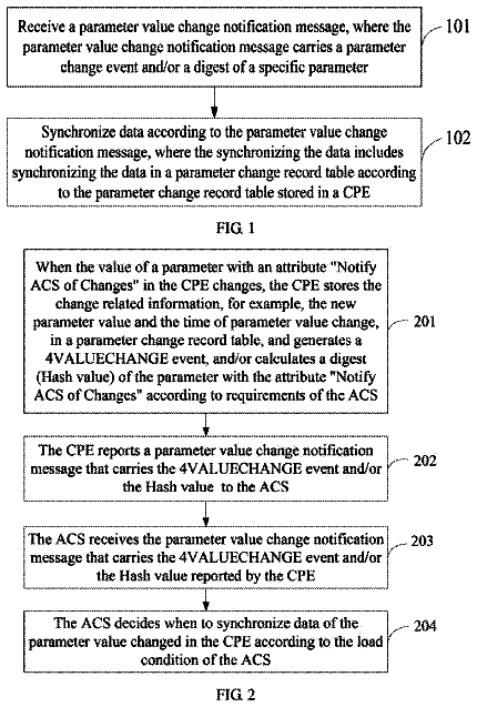
Method, apparatus, and system for data synchronization
A method, an apparatus, and a system for data synchronization are disclosed.
US 8,631,100 B2 · Assignee: Juniper Networks, Inc. · Inventors: Gandhewar; Sunil et al.
Sheet 1 of 7 from the published document. All sheets in the USPTO PDF
In general, techniques are described for automatic assignment of hardware addresses within computer networks. As one example, a network device comprising a physical network interface and a control unit may implement these techniques. The network interface receives a first message from a client device requesting a layer three (L3) network address. The first message also includes a layer two (L2) hardware address currently assigned to a network interface of the client device. The control unit selects a replacement L2 hardware address for use by the network interface of the client device as a replacement for the L2 hardware address included in the first message and generates a second message having a field that specifies the replacement L2 hardware address. The network interface outputs the second message to the client device so as to automatically assign the replacement L2 hardware address for use by the network interface of the client device.
A computer network is a collection of interconnected computing devices that exchange data and share resources. In a packet-based network, such as the Internet, the computing devices communicate data by dividing the data into small blocks called packets. The packets are individually routed across the network from a source device to a destination device. The destination device extracts the data from the packets and assembles the data into its original form. Dividing the data into packets enables the source device to resend only those individual packets that may be lost during transmission. To route the packets through the computer network, each network device may be assigned an address that uniquely identifies each of the requesting network devices. Each packet may then include a source address uniquely identifying the network device that originated the packet and a destination address uni
All 7 drawing sheets from the published document, cropped to the drawing.
What the patent claimed, word for word. All of it is now free to use.
The invention relates to computer networks and, more particularly, allocating hardware addresses for use by network devices within computer networks.
A computer network is a collection of interconnected computing devices that exchange data and share resources. In a packet-based network, such as the Internet, the computing devices communicate data by dividing the data into small blocks called packets. The packets are individually routed across the network from a source device to a destination device. The destination device extracts the data from the packets and assembles the data into its original form. Dividing the data into packets enables the source device to resend only those individual packets that may be lost during transmission.
To route the packets through the computer network, each network device may be assigned an address that uniquely identifies each of the requesting network devices. Each packet may then include a source address uniquely identifying the network device that originated the packet and a destination address uniquely identifying the network device to which the packet is destined. Intermediate devices, referred to as routers, may route the packets to the destination device based on the destination address included within the packet.
Before attempting to access the network, each network device may request configuration information that includes an Internet Protocol (IP) address in accordance with a Dynamic Host Configuration Protocol (DHCP). For example, a subscriber device (e.g., a cable modem, a digital television setup box, a Digital Subscriber Line (DSL) modem) may request a layer three IP network address by issuing a DHCP request. The DHCP request issued by the subscriber device may specify a hardware address, e.g. MAC address, of a network interface of the requesting network device. This hardware address is typically configured within a network interface card at the time of manufacture and is commonly used within the computer network to uniquely identify the requesting device. A DHCP server or other system that maintains an IP address space for the network may receive this request, reserve an IP address with the IP address space and assign the IP address to the requesting network device. The DHCP server then formulates a response in the form of layer two (L2) message and forwards the response back to the network device so as to assign the reserved IP address to the requesting network device. To forward this response back to the network device, the DHCP server formulates the L2 message with the hardware address specified in the DHCP request as the destination address.
In general, techniques are described for automatically assigning hardware addresses within computer networks in a manner that ensures the hardware addresses are unique within the computer network. For example, although manufacturers of the network interface cards and network devices attempt to utilize hardware addresses that are globally unique, in some cases conflicts may occur once the devices are deployed within customer networks. For example, each manufacturer may maintain different addresses spaces from which to select hardware addresses, but may re-use hardware addresses over time, resulting in instances where two or more different physical network interfaces are manufactured with the same hardware address. If these network devices are ultimately deployed in the same sub-network or a network that requires its network devices to be uniquely identifiable, communications using those addresses result in conflicts that may be unresolvable.
To illustrate, consider that the DHCP response described above relies on the hardware address from the DHCP request to identify which of the network devices should receive the DHCP response. If two or more network devices are each assigned the same hardware address, the intermediate devices positioned between the DHCP server and these network devices or the DHCP server itself cannot determine to which of these network devices to forward the DHCP response. In this respect, protocols that rely on hardware addresses to uniquely identify network devices, such as DHCP, may be unable to properly resolve to which network device a given communication or message is to be sent. In the case of DCHP, this inability to uniquely identify a network device may prevent assignment of an IP address to this network device, which may effectively prevent the network device from being able to access a public network, such as the Internet.
The techniques described herein may utilize the dynamic host configuration protocol (DHCP) to perform the automatic reassignment of hardware addresses after a network device is deployed within a network. In particular, the techniques described herein may be used to extend DHCP to include a define DHCP option referred to herein as a "New Hardware Address" option that specifies a new hardware address for use in reprogramming the existing hardware address pre-programmed into the network interface by the manufacture of the network interface. In this way, the techniques may enable a DHCP server to provide a new hardware address in a DHCP response communication for use by a requesting network device, or so-called "client" in the context of DHCP. If the requesting network device supports the techniques describe in this disclosure, the requesting network device or client may automatically reprogram its network interface to replace the existing pre-programmed hardware address with the new hardware address provided via the "New Hardware Address" DHCP option. In this manner, the techniques enable automatic assignment of hardware addresses to prevent hardware address conflicts within a computer network.
The techniques may provide one or more benefits. For example, the techniques may reduce administrative oversight as the assignment of hardware addresses to prevent hardware address conflicts occurs automatically. That is, the administrator of any given computer network may configure the DHCP server to perform the automatic assignment of hardware addresses in accordance with the techniques of this disclosure, whereupon the DHCP server may proceed to implement these techniques without requiring any human or administrative intervention. Rather than require administrators to manually interface with each network device within a given uniquely addressable computer network and execute software or other commands to reprogram a hardware address of each network interface, the techniques may automatically determine when to assign a new hardware address, e.g., upon detecting a hardware address conflict, and then assign the new hardware address to overcome this hardware address conflict. Moreover, the administrator need not ensure that clients having network interfaces programmed with the same hardware address are assigned to different uniquely addressable computer networks, e.g., sub-networks, but can rely on the techniques to ensure that hardware address conflicts do not occur within these uniquely addressable computer networks. The techniques may therefore reduce overhead associated with planning and maintaining computer networks as well as complications associated with connecting clients to the public network.
In one embodiment, a method comprises receiving, with a network device of a network, a first message from a client device of the network, wherein the first message requests that a layer three (L3) network address be reserved for use by the client device, and wherein the first message also includes a layer two (L2) hardware address currently assigned to a physical network interface of the client device and selecting, with the network device, a replacement L2 hardware address for use by the network interface of the client device as a replacement for the L2 hardware address included in the first message. The method also comprises generating, with the network device, a second message having a field that specifies the replacement L2 hardware address, and outputting, with the network device, the second message to the client device in response to the first message so as to automatically assign the replacement L2 hardware address for use by the network interface of the client device.
In another embodiment, a network device comprises a physical network interface that receives a first message from a client device of a network, wherein the first message requests that a layer three (L3) network address be reserved for use by the client device, and wherein the first message also includes a layer two (L2) hardware address currently assigned to the network interface of the client device and a control unit that selects a replacement L2 hardware address for use by the network interface of the client device as a replacement for the L2 hardware address included in the first message and generates a second message having a field that specifies the replacement L2 hardware address. The network interface outputs the second message to the client device in response to the first message so as to automatically assign the replacement L2 hardware address for use by the network interface of the client device.
In another embodiment, a non-transitory computer-readable storage medium comprises instructions that cause a processor of a network device to receive a first message from a first client device of the network, wherein the first message requests that a layer three (L3) network address be reserved for use by the client device, and wherein the first message also includes a layer two (L2) hardware address associated with an network interface of the client device, select a replacement L2 hardware address for use by the network interface of the client device as a replacement for the L2 hardware address included in the first message, generate a second message having a field that specifies the replacement L2 hardware address and output the second message to the client device in response to the first message so as to automatically assign the replacement L2 hardware address for use by the network interface of the client device.
In another embodiment, a method comprises generating, with a client device located in a sub-network (subnet) of a network, a first message requesting that a layer three (L3) network address be reserved for use by the client device in the network, wherein the first message also includes a layer two (L2) hardware address associated with an network interface of the client device and outputting, with the client device, the first message to a network device responsible for allocating leases for L3 network addresses to client devices. The method also comprises receiving, with the client device, a second message having a field that specifies a replacement L2 hardware address for use in the network as a replacement for the L2 hardware address included in the first message and automatically replacing, with the client device, the L2 hardware address associated with the network interface of the client device with the replacement L2 hardware address specified in the second message.
In another embodiment, a client device comprises a physical network interface and a control unit that generates a first message requesting that a layer three (L3) network address be reserved for use by the client device in the network, wherein the control unit generates the first message to specify a layer two (L2) hardware address currently assigned to the physical network interface of the client device. The network interface outputs the first message to a network device responsible for allocating leases for L3 network addresses to client devices and receives a second message having a field that specifies a replacement L2 hardware address for use in the network as a replacement for the L2 hardware address included in the first message. The control unit outputs one or more signals to the physical network interface to automatically replace the L2 hardware address currently assigned to the network interface with the replacement L2 hardware address specified in the second message.
In another embodiment, a non-transitory computer-readable storage medium comprises instructions that cause a processor of a client device to generate a first message requesting that a layer three (L3) network address be reserved for use by the client device in a network, wherein the first message also includes a layer two (L2) hardware address associated with a network interface of the client device, output the first message to a network device responsible for allocating leases for L3 network addresses to client devices, receive a second message having a field that specifies a replacement L2 hardware address for use in the network as a replacement for the L2 hardware address included in the first message and automatically replace the L2 hardware address associated with the network interface of the client device with the replacement L2 hardware address specified in the second message.
In another embodiment, network system comprising a client device located in a sub-network (subnet) of a network and a dynamic host configuration protocol (DHCP) server located in the network that is responsible for allocating leases for L3 network addresses to client devices. The client device includes a first physical network interface and a first control unit that generates a first message requesting that a layer three (L3) network address be reserved for use by the client device in the network, wherein the first message also includes a layer two (L2) hardware address associated with the first network interface of the client device. The first network interface outputs the first message to the DHCP server. The DHCP server includes a second physical network interface that receives the first message from the client device and a second control unit that selects a replacement L2 hardware address for use by the first network interface of the client device as a replacement for the L2 hardware address included in the first message and generates a second message having a field that specifies the replacement L2 hardware address. The second network interface outputs the second message to the client device. The first network interface of the client device receives the second message. The first control unit automatically replaces the L2 hardware address associated with the first network interface of the client device with the replacement L2 hardware address specified in the second message.
In another embodiment, a method comprises generating, with a client device located in a sub-network (subnet) of a network, a first message requesting that a layer three (L3) network address be reserved for use by the client device in the network, wherein the first message also includes a layer two (L2) hardware address associated with an network interface of the client device, outputting, with the client device, the first message to a network device responsible for allocating leases for L3 network addresses to client devices, receiving, with the client device, a second message having a field that specifies a replacement L2 hardware address for use in the network as a replacement for the L2 hardware address included in the first message and indicating, with the client device, to a user of the client device that the user needs to change the L2 hardware address to the replacement L2 hardware address.
The details of one or more embodiments of the techniques are set forth in the accompanying drawings and the description below. Other features, objects, and advantages of the techniques will be apparent from the description and drawings, and from the claims.
FIG. 1 is a block diagram illustrating an exemplary network system in which a network device represented by dynamic host configuration protocol (DHCP) server implements the automatic hardware address assignment techniques described in this disclosure.
FIG. 2 is a block diagram illustrating the DHCP client device and the DHCP server in more detail.
FIGS. 3A-3B are flowcharts illustrating example operation of DHCP client device and a DHCP server in implementing various aspects of the techniques described in this disclosure.
FIGS. 4A-4B are flowcharts illustrating another example operation of DHCP client device and a DHCP server in implementing various aspects of the techniques described in this disclosure.
FIG. 5 is an illustration showing an exemplary format for a DHCP message specifying a new indicator field and a new hardware address option field in accordance with the techniques described in this disclosure.
FIG. 1 is a block diagram illustrating an exemplary network system 10 in which a network device represented by dynamic host configuration protocol (DHCP) server 16 implements the automatic hardware address assignment techniques described in this disclosure. In the example of FIG. 1, device 16 is shown as a Dynamic Host Configuration Protocol (DHCP) server 16, however, the automatic hardware address techniques may be implemented by any network device, such as a router, a switch, a hub, a computer or any other device capable of receiving and communicating messages for the reservation of resources within a network system, such as network system 10. Moreover, while described with respect to a particular protocol for reserving resource, e.g., DHCP, the techniques may apply to any network address allocation protocol by which a network device may request and reserve network addresses for operating within network system 10.
As shown further in the example of FIG. 1, network system 10 includes a network 14 and a DHCP relay device 12, where DHCP relay device 12 and a DHCP server 16 couple to network 14 via respective network links 18A, 18B. Network 14 may represent any publically accessible computer network, such as the Internet. Network 14 may include a wide variety of interconnected computing devices or nodes, such as web servers, print servers, application servers, data servers, workstations, desktop computers, laptop computers, cellular or other mobile devices, Personal Digital Assistants (PDAs), and any other device cable of connecting to a computer network via a wireless and/or wired connection. Typically, these devices communicate with one another via a packet-based protocol, such as an Internet Protocol (IP)/Transmission Control Protocol (TCP). As a result, network 14 may represent or be referred to as a "packet-based" or an "IP packet-based" computer network.
DHCP server 16 may represent a network device that allocates layer three network addresses (e.g., IP network addresses) for network system 10. In particular, DHCP server 16 may maintain access to an address pool, such as an Internet Protocol (IP) address pool. DHCP server 16 may also maintain access to other resources, such as configuration files that provide pertinent configuration information. DHCP server 16 may reserve an IP address within the IP address pool for use by one or more DHCP clients, such as DHCP client devices 20A, 20B ("DHCP client devices 20"), in accordance with DHCP, as described in more detail below.
Network system 10 may further include DHCP client devices 20A, 20B ("DHCP client devices 20"), each of which couple to DHCP relay device 12 via one or more connections (not shown) included within sub-network 22 ("subnet 22"). DHCP client devices 20 may each represent a subscriber device, such as one or more of a Set-Top Box (STB), a personal computer, a laptop computer, a modem, a workstation, a personal digital assistant (PDA), a cellular phone or other mobile device (e.g., a so-called "smart phone") or any other device capable of accessing a network, such as network 14. These devices 20 may be "DHCP clients" in that these devices implement DHCP to request, as a client to the DHCP server or host device 16, L3 network addresses (e.g., IP addresses) and other resources maintained by DHCP server 16 useful or required for operating within network system 10.
Subnet 22 may represent a portion of a larger network, which is not shown in FIG. 1 for ease of illustration purposes, hence the name "subnet." The larger network may be generally referred to as an access network in that this network enables client devices to access network 14. As subnet 22 comprises a portion of this access network and similarly facilitates access of network 14 by client devices 20, subnet 22 may similarly be referred to as an access network. Generally, access networks implement IP, and with respect to IP, subnets or IP subnets, such as subnet 22, may be identified by an IP address prefix.
An IP subnet may represent a "network area" in that the IP subnet may be identified by a contiguous set of IP addresses or an IP prefix that defines a distinct area within an IP address space of the larger access network. The IPv4 address space comprises 2.sup.32 distinct IP addresses, as each IP address may correspond to a 32-bit binary number. Typically, an IP address is presented in four eight bit binary numbers (or, in other words, four bytes) with each eight bit binary number or byte separated by a period (.), which is a notation referred to as a quad-dotted decimal representation. For example, one IP address may be presented as 10.0.0.1. However, as a byte may represent a number as large as 2.sup.8-1 or 255.sub.10, each byte may represent a range of numbers from 0 to 255 in decimal, such that each IP address may vary from 0.0.0.0 to 255.255.255.255 again in quad-dotted decimal representation or notation.
An IP prefix identifies a subset of addresses with the IP address space and those addresses may be assigned to devices within a particular area within the larger access network. An IP prefix usually identifies a contiguous set of IP addresses within the IP address space. For example, an IP prefix may identify a contiguous set of IP addresses from 10.0.0.1 to 10.0.0.255. This IP prefix may be represented by a routing prefix or 10.0.0 followed by a subnet mask identifier (which in this instance may be represented as 24.sub.10 to indicate that the first 24 bits should be 1's within the subnet mask, e.g., 255.255.255.0 in quad-dotted decimal notation), where the prefix and scope identifier may be separated by a slash (/). The IP prefix may therefore be presented as 10.0.0.0/24 suggesting that only the first 24 bits of the 32-bit IP address are necessary to reach the IP subnet (or area) corresponding to the IP prefix. In this instance, the IP prefix may define a routing prefix and may represent a summarized version of the contiguous set of IP addresses.
According to DHCP, each subnet, such as subnet 22, requires either a DHCP server, such as DHCP server 16, or a DHCP relay device, such as DHCP relay device 12, by which to reserve and assign IP addresses to network devices, such as DHCP client devices 20, operating within the respective subnet. As DHCP servers may maintain network resources for a large number of DHCP clients, often, for small subnets, network administrators will utilize one or more DHCP servers or server clusters to service a number of subnets. To do so, the network administrators may maintain one DHCP server, such as DHCP server 16, in a central location and then configure multiple DHCP relay devices, one or more for each subnet, to relay DHCP messages from DHCP clients located within the respective one of the subnets to the single DHCP server or server cluster. While network system 10 shown in the example of FIG. 1 is configured according to this second alternative where the DHCP relay device relays messages between the subnet and the DHCP server, the techniques may apply equally in network systems 10 that include client devices and DHCP servers located in the same subnet.
Typically, in these instances, a router or other network device already present within each subnet may provide this DHCP relay service as an optional service that the network administrators may enable in this context. In this respect, DHCP relay device 12 may represent a router or some other similar network device, such as a switch or a hub that provides this DHCP relay service as an optional service. Alternatively, DHCP relay device 12 may represent a dedicated relay device and may comprise any device capable of relaying DHCP messages in the manner described below in more detail. Thus, DHCP relay device 12 may represent any intermediate network device positioned between DHCP client devices 20 and DHCP server 16 that implements DHCP to relay DHCP messages between DHCP clients 20 and DHCP server 16.
Generally, upon booting up or otherwise powering up and initializing its various components, DHCP client devices 20 attempt to secure an IP address for use in accessing network 14. For example, when initialing various hardware components during the power on process, DHCP client device 20A may initialize an interface card, which is not shown in the example of FIG. 1 for ease of illustration purposes. Typically, the interface card stores data defining a layer two (L2) network address, which was statically programmed by a manufacture of the interface card. This L2 hardware address is also referred to commonly as a "hardware address" as this L2 hardware address identifies the hardware, i.e., the interface card in this example. One example of a hardware address is a media access control (MAC) address. Reference to layers throughout this disclosure followed by a number is intended to indicate the corresponding layer in the Open Systems Interconnections (OSI) model.
When initializing this interface card, DHCP client device 20A issues a DHCP message 24A that is commonly referred to as a DHCP discover message. This DHCP discover message 24A initiates the DHCP process by which DHCP client device 20A requests that a layer three (L3) network address, where an IP address is one example of a L3 network address, be reserved for use by DHCP client device 20A. In most instances, the DHCP discover message includes a field that stores the L2 hardware address stored by the interface card, where this L2 hardware address is supposed to uniquely identify this interface card of DHCP client device 20A within at least subnet 22 and, potentially, network 14.
While this L2 hardware address is supposed to uniquely identify the interface card of DHCP client device 20A, the manufacturers of such interface cards and other hardware components that require L2 hardware addresses often reuse hardware or L2 addresses such that two or more interface cards from the same manufactures may, in fact, be assigned the same L2 hardware address. Many protocols, such as DHCP, however assume that the L2 hardware address assigned to each interface card is unique within the subnet. In instances where two or more DHCP client devices each include interface cards or other hardware components that are assigned the same L2 hardware address, network operations may be impacted due to the inability to resolve this L2 hardware address as belonging to a single DHCP client device.
To illustrate, consider an instance where both DHCP client devices 20A, 20B include a single interface card assigned the same L2 hardware address. As noted above, DHCP client device 20A issues a DHCP discover message 24A, which includes a field that stores the L2 hardware address assigned to the interface card of DHCP client device 20A. DHCP relay device 12 relays this message 24A to DHCP server 16, which responds with a DHCP offer message 28A. Again, DHCP relay device 12 relays this message 28A to DHCP client device 20A. DHCP offer message 28A offers DHCP client device 20A a lease reserving a L3 network address for use by DHCP client device 20A. Assuming DHCP client device 20A accepts this lease presented in DHCP offer message 28A, DHCP client device 20A generates and issues a DHCP request message 32A requesting the lease offered in DHCP offer message 28A. DHCP relay device relays this message to DHCP server 16, which responds with a DHCP acknowledgment (ACK) message 34A acknowledging that lease for the L3 network address has been accepted by DHCP client device 20A. Again, DHCP relay device 12 relays this message to DHCP client device 20A. After receiving DHCP ACK message 34A, DHCP client device 20A assigns the leased L3 network address for use by its interface card. More information regarding DHCP in general, and specifically the various messages 26A, 28A, 32A, 34A, can be found in Request for Comments (RFC) 2131, entitled "Dynamic Host Configuration Protocol," dated March 1997, the entire contents of which are incorporated herein as if set forth in its entirety.
At some point in time after DHCP client device 20A has secured its lease for the L3 hardware address, DHCP client device 20B generate and issue a DHCP discover message 24B while powering up or otherwise initializing its single interface card assigned the same L2 hardware address as that of the interface card of DHCP client device 20A. DHCP discover message 24B also includes a field that stores the L2 hardware address assigned to the interface card of DHCP client device 20B. In this instance, this field stores the same L2 hardware address as stored by this field in DHCP discover message 24A. DHCP server 16 receives this discover message 24B and parses this field to extract the L2 hardware address. DHCP server 16 usually stores data defining a table that associates L2 hardware addresses with corresponding L3 network addresses reserved for use by the hardware components identified by the corresponding L2 hardware addresses.
Using the L2 hardware address parsed from DHCP discover message 24B, DHCP server 16 identifies an entry in this table that identifies an association between this L2 hardware address and the L3 network address assigned to DHCP client device 20A. That is, because the interface cards of both DHCP client devices 20 are assigned the same L2 hardware address, DHCP server 16 cannot properly resolve to which one of DHCP client devices 20 the L2 hardware address identifies. DHCP server 16, in this instance, more than likely responds to DHCP discover message 24B with DHCP offer message 28B offering the same lease for the same IP address offered to DHCP client device 20A. Assuming DHCP client device 20B accepts the lease for the L3 network address presented in DHCP offer message 28B via a DHCP request message 32B and DHCP server 16 acknowledges this acceptance via a DHCP ACK message 34B, the interface cards of both DHCP client devices 20 may be using the same L3 network address. This dual use of the same L3 network address presents a number of conflicts in routing L3 packets to the correct one of DHCP client devices 20, as again, it is generally assumed throughout the network that a L3 network address uniquely identifies any given client device within at least subnet 22.
Alternatively, DHCP server 16 may incorrectly assume that DHCP discover message 24B originated from DHCP client 20A. In this instance, DHCP server 16 releases the MAC address and IP address binding associating the IP address assigned to DHCP client 20A with the non-unique MAC address. After releasing this binding, DHCP server 16 then responds with a DHCP offer message offering another IP address for use by the requesting one of DHCP clients 20. In this respect, DHCP server 16 configures subnet 22 such that only one of DHCP clients 20 having the same MAC address is assigned an IP address, resulting in only one of DHCP clients 20 being able to access public network 14. Moreover, DHCP relay device 12 normally unicast DHCP messages, and in this instance, both of DHCP client devices 20 may receive this DHCP offer message. DHCP client 20A, having already accepted its lease for the IP address, may not be able to understand this message considering that it did not originate DHCP discover message 24B. DHCP client 20A may then experience issues as a result of not understanding this message with respect to its current state.
To avoid this issues, network administrators may manually configure network system 10 such that each of DHCP client devices 20 having hardware components assigned the same L2 hardware address reside in different subnets, which may represent a network that requires unique addressability to properly function. However, manually configuring network system 10 in this manner is often tedious, time consuming and prone to error. Moreover, each subnet configured for this purpose also requires its own DHCP relay device similar to DHCP relay device 12, which may increase the cost in setting up and maintaining this network system 10. Furthermore, this solution does not protect against instances where devices move between subnets, which is becoming increasingly common considering the growth of portable computers, such as laptops, so-called smart phones, and slate computers. To illustrate, assume the network administrator configured each of DHCP client devices 20 such that each resides in its own subnet similar to subnet 22. This may effectively prevent addressing conflicts between DHCP client devices 20. However, if DHCP client device 20B is moved such that is accesses network 14 from the subnet in which DHCP client device 20A resides, the addressing conflict described above results.
Another way to avoid these types of addressing issues or conflicts (even in instances where the network administrator has manually configured the network system such that each of these devices reside in separate subnets) is to manually reprogram the hardware components or software that controls the hardware components to use a different L2 hardware address. This manually reprogramming generally requires a network administrator to interface with each DHCP client device and reprogram those devices often using software, which again is tedious, time consuming and prone to error. In large networks having hundreds, thousands, if not tens of thousands of DHCP client devices per subnet, both solutions to overcome these addressing conflicts require substantial time and potentially increase administrative costs in terms of maintaining a consistent addressing strategy.
In accordance with the automatic L2 hardware address assignment techniques described in this disclosure, DHCP server 16 may automatically (which in this instance may indicate that no administrative oversight is required other than to initially provision or configure this automatic hardware address assignment service) assign a L2 hardware address for use by a requesting one of DHCP client devices 20 so as to avoid these addressing conflicts. Considering this assignment of these hardware addresses is automatic, the network administrator need not spend time manually configuring each address conflicted DHCP client devices, such as DHCP client devices 20, to reside within its own subnet, such as subnet 22, or to reprogram L2 hardware addresses stored by the interface cards of these address conflicted DHCP client devices. As a result, the techniques may reduce the amount of time required to provision a new DHCP client device to access network 14, especially considering that the automatic hardware address assignment techniques described in this disclosure may reduce if not eliminate configuration error that often results when manually configuring networks.
To illustrate these automatic hardware address assignment techniques, assume DHCP client device 20A issues DHCP discover message 24A to DCHP server 16. In some instances, DHCP client device 20A may signal whether or not it supports automatic hardware address assignment in DHCP discover message 24A. In these instances, DHCP client device 20A sets a flag or defines another new option referred to as a "Supports Configurable Hardware Address" option or includes a "New Hardware Address" option within a so-called "parameter request list option" in DHCP discover message 24A to signal its support of the automatic hardware address assignment techniques described in this disclosure. DHCP client device 20A generally includes a DHCP client software module (which represents software instructions) that executes within a hardware module, such as a processor. If DHCP client device 20A supports the techniques described in this disclosure, this DHCP client software module may include a hardware address programming module that is capable of dynamically reprogramming either an operating system or some other management software or the interface card itself to replace the manufacturer programmed L2 hardware address (which, again may be referred to as a hardware address) with a L2 hardware address specified by DHCP server 16.
DHCP server 16 receives DHCP discover message 24A and parses this DHCP discover message 24A to extract the indication of whether DHCP client device 20A supports the automatic hardware address assignment techniques described in this disclosure. If this indicator indicates that DHCP client device 20A does not support the techniques described in this disclosure, DHCP server 16 proceeds to respond in a conventional manner so as to provide a lease for at least one network resource, e.g., a L3 network address, to DHCP client device 20A. Alternatively, DHCP server 16 may be administratively configured not to allow such clients. In which case, DHCP server 16 denies such clients by not sending the DHCP offer message. As another alternative, if two ore more clients are determined to be using the same hardware address, DHCP server 16 can either deny this new client or use the above described conventional method depending upon the administrative configuration. However, if this indicator indicates that DHCP client device 20A supports the automatic hardware address assignment techniques described in this disclosure, DHCP server 16 performs one of two variations of the techniques to automatically assign a replacement hardware address for use by DHCP client device 20A.
In the first variation of these techniques, DHCP server 16 always assigns a replacement L2 hardware address regardless of whether the L2 hardware address is provided as a source address in DHCP discover message 24A. DHCP server 16 stores data defining a L2 hardware address pool that generally represents a contiguous set of L2 hardware addresses reserved for use by the network service provider that owns and operates network system 10. DHCP server 16 selects a next available L2 hardware address from the L2 hardware address pool and generates DHCP offer message 28A in such a manner that it includes the selected L2 hardware address as a replacement L2 hardware address. In some instances, this replacement L2 hardware address is specified within DHCP offer message 28A in a new type-length-value (TLV) field that may be referred to as either a "new hardware address field" or a "replacement hardware address field." DHCP server 16 then outputs this DHCP offer message 28A to DHCP client device 20A.
The description continues in the full USPTO document.
About 6,211 words. The USPTO PDF has it with every drawing.
Fees are due 3.5, 7.5 and 11.5 years after grant. This patent expired on January 14, 2026, so the fee marked "not paid" was the one that went unpaid.
AUTOMATIC ASSIGNMENT OF HARDWARE ADDRESSES WITHIN COMPUTER NETWORKS
Filed Jul 2010 · published Jan 2012Automatic assignment of hardware addresses within computer networks
Filed Jul 2010 · granted Jan 2014Earlier publications, parents and continuations. None of them can still be enforced, or this patent would not be listed.
Prior art cited by the examiner or applicant. Useful when you check your own idea for novelty.
Everything on this page comes from the documents linked above.


