Lapsed, fee not paid7 drawings
Telecom & Networks · US 8,630,290 B1
Using a DFA unit for classification list processing
Systems and methods can operate to use a deterministic finite automata module to classify data.
US 8,630,314 B2 · Assignee: Faro Technologies, Inc. · Inventors: York; Frederick John
Sheet 1 of 29 from the published document. All sheets in the USPTO PDF
Apparatus includes at least two devices that communicate with each other, wherein a first one of the at least two devices having an IEEE 1588 precision time protocol interface, the interface including one or more components configured for communications in both a wired manner and a wireless manner with a second one of the at least two devices. The second one of the at least two devices having an IEEE 1588 precision time protocol interface, the interface including one or more components configured for communications in both a wired manner and a wireless manner with the first one of the at least two devices. Wherein one of the at least two devices includes a master clock and the other one of the at least two devices includes a slave clock, wherein the master clock communicates a time to the slave clock and the slave clock is responsive to the communicated time from the master clock to adjust a time of the slave clock if necessary to substantially correspond to the time of the master clock, thereby time synchronizing the at least two devices together.
The invention relates generally to the time synchronization of measurements taken by multiple measurement devices, and more particularly to the time synchronization of measurements taken by multiple metrology devices such as articulated arm coordinate measuring machines, laser trackers, laser scanners, and other types of parts measurement precision metrology devices. For example, one of these metrology devices may belong to a class of instruments that measure the coordinates of each of a number of points on an object or part to be measured by probing the point with an articulated mechanical structure. The probing may be performed with a contacting mechanical probe tip and/or with a non-contacting scanning device (e.g., a laser line probe (LLP)). The position of the probe tip or scanning device relative to the base of the structure (i.e., in a certain coordinate frame of reference) is det
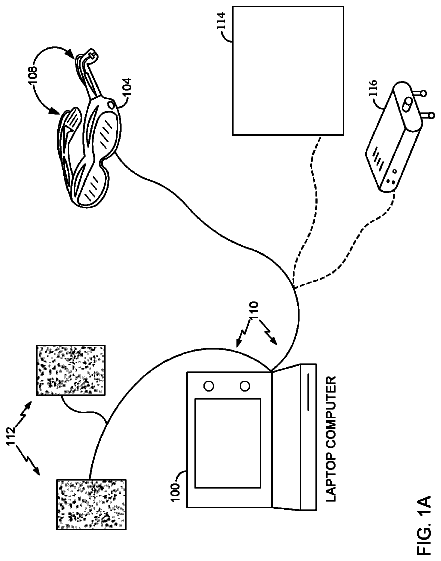
1 of 29 drawing sheets so far from the published document, cropped to the drawing. Every sheet is in the USPTO PDF.
What the patent claimed, word for word. All of it is now free to use.
The invention relates generally to the time synchronization of measurements taken by multiple measurement devices, and more particularly to the time synchronization of measurements taken by multiple metrology devices such as articulated arm coordinate measuring machines, laser trackers, laser scanners, and other types of parts measurement precision metrology devices.
For example, one of these metrology devices may belong to a class of instruments that measure the coordinates of each of a number of points on an object or part to be measured by probing the point with an articulated mechanical structure. The probing may be performed with a contacting mechanical probe tip and/or with a non-contacting scanning device (e.g., a laser line probe (LLP)). The position of the probe tip or scanning device relative to the base of the structure (i.e., in a certain coordinate frame of reference) is determined by the readings of angular encoders located at the connection points (e.g., bearing cartridges) of the articulating arm segments. This type of device, whether it uses a mechanical probe tip or a scanner, is referred to as an articulated arm coordinate measuring machine.
Portable articulated arm coordinate measuring machines (AACMMs) have found widespread use in the manufacturing or production of parts where there is a need to rapidly and accurately verify the dimensions of the part during various stages of the manufacturing or production (e.g., machining) of the part. Portable AACMMs represent a vast improvement over known stationary or fixed, cost-intensive and relatively difficult to use measurement installations, particularly in the amount of time it takes to perform dimensional measurements of relatively complex parts. Typically, a user of a portable AACMM simply guides a probe along the surface of the part or object to be measured. The measurement data are then recorded and provided to the user. In some cases, the data are provided to the user in visual form, for example, three-dimensional (3-D) form on a computer screen. In other cases, the data are provided to the user in numeric form, for example when measuring the diameter of a hole, the text "Diameter=1.0034" is displayed on a computer screen.
An example of a prior art portable articulated arm CMM is disclosed in commonly assigned U.S. Pat. No. 5,402,582 ('582), which is incorporated herein by reference in its entirety. The '582 patent discloses a 3-D measuring system comprised of a manually-operated articulated arm CMM having a support base on one end and a measurement probe at the other end. Commonly assigned U.S. Pat. No. 5,611,147 ('147), which is incorporated herein by reference in its entirety, discloses a similar articulated arm CMM. In the '147 patent, the articulated arm CMM includes a number of features including an additional rotational axis at the probe end, thereby providing for an arm with either a two-two-two or a two-two-three axis configuration (the latter case being a seven axis arm).
Another type of these devices may be an instrument, referred to as a laser tracker, which measures the coordinates of a point by sending a laser beam to a retroreflector target that is in contact with the point. The laser tracker determines the coordinates of the point by measuring the distance and the two angles to the retroreflector. The distance is measured with a distance-measuring device such as an absolute distance meter or an interferometer. The angles are measured with an angle-measuring device such as an angular encoder. A gimbaled beam-steering mechanism within the instrument directs the laser beam to the point of interest. Exemplary systems belonging to this class of instruments are described by U.S. Pat. No. 4,790,651 to Brown et al. and U.S. Pat. No. 4,714,339 to Lau et al.
A laser tracker can measure relatively large parts (i.e., parts larger than what a portable AACMM can measure without relocation of the AACMM) and in a shorter amount of time as compared to a portable AACMM, especially if the portable AACMM must be relocated to completely measure the part. Modern laser trackers can measure relatively large parts with 3-D single-point accuracy to 0.001 inches. Such a laser tracker typically uses its laser to measure the 3-D coordinates or a point at a range of up to 230 ft (70 m) by following the movement of a retroreflector such as a spherically mounted retroreflector (SMR) and report on the measured position in real time. Some modern laser trackers can provide real time updates of SMR positions.
There are several types of laser scanners, but all types project light onto objects to be tested or measured. Most surfaces of these objects are diffusely scattering, and measurements are ordinarily made without the assistance of a cooperative target such as a retroreflector. Some scanners, such as the one that attaches to the end of the AACMM described above (e.g., an LLP), are moved by hand and the laser light is directed over a surface of the object. The contacting probe of the portable AACMM and the non-contacting laser line probe can digitize data interchangeably without having to remove either component from the AACMM. A laser line probe provides multiple sampling points to be taken simultaneously along an object's surface, which is illuminated by the laser scan line. Users can accurately measure prismatic features with the AACMM contacting probe, then laser scan sections requiring larger amounts of data (detailed feature extraction) at more than 19,000 points per-second--without adding or removing attachments. An exemplary non-contacting scanner of this type is described in commonly assigned U.S. Pat. No. 6,965,843 to Raab et al., which is incorporated herein by reference in its entirety.
Other scanners are stationary and illuminate an entire area of interest. An exemplary scanner of this type is described in U.S. Pat. No. 7,599,071 to Dillon et al. A third type of laser scanner sends a laser beam over a scan pattern that covers a large volume. A laser scanner of this type may sometimes measure the 3-D coordinates of a relatively large volume within a few minutes. An exemplary laser scanner of this type is described in commonly assigned U.S. Pat. No. 7,430,068 to Becker et al., which is incorporated by reference herein in its entirety.
There are many situations in which multiple metrology devices, either all of the same type or of different types, being connected, arranged or combined in a distributed networked system, may benefit from being synchronized in time to one another. In general, as distributed network technologies increase in number and complexity, these system technologies applied to measurement and control become more complex as the number of nodes (i.e., metrology devices) in the system increases. It has become common to utilize local real time clocks in the various devices to achieve relatively accurate system-wide time. However, each of these individual clocks tends to drift apart from one another (i.e., lose their system-wide synchronization) due to, for example, initial frequency offsets, instabilities in the clock oscillators and environmental conditions such as temperature, aging, vibration, mechanical stresses, etc. As such, the measurements taken by these various devices and any resulting control imparted to the overall system suffer from the time inaccuracies of the individual clocks. Thus, some type of clock time synchronization correction or adjustment is needed to properly synchronize the individual clocks to thereby maintain an accurate and common measure of system-wide time.
The following outlines five examples in which precise time synchronization benefits system combinations of precision metrology devices.
Tracker and Arm: The portable AACMM is capable of being moved or positioned into a variety of different orientations. Because of this, the portable AACMM is able to measure "hidden" points; that is, points that are hidden from a line-of-sight view of a measuring device such as a laser tracker. On the other hand, the laser tracker can measure over a much larger volume than the AACMM. It is possible to use a laser tracker to relocate a portable AACMM by attaching a retroreflector to the arm portion of the AACMM. In this way the best features of each device are retained, while enabling the combined system to accurately measure hidden points over a relatively large volume.
An exemplary method for physically relocating the portable AACMM in this way is described in commonly assigned U.S. Pat. No. 7,804,602 to Raab, which is incorporated by reference herein in its entirety. To obtain the best possible relocation, it is important that the portable AACMM and the laser tracker be accurately synchronized in time to one another so that the corresponding measurements made by each device (e.g., of the position of the retroreflector) are accurately synchronized during the relocation process.
Simultaneous multilateration: By using the highly accurate distance meters (e.g., interferometers or absolute distance meters) of a multiple of laser trackers to simultaneously measure a single, wide-angle retroreflector target, the 3-D coordinates of the target can be measured to a relatively high degree of accuracy. It is desirable to make such a simultaneous multilateration measurement on a moving target. This enables the target to be moved over surfaces of objects of interest, thereby producing a map of the surface contours. To retain the relatively high accuracy obtained with this method, the multiple trackers must be accurately synchronized in time.
Wireless synchronization of scanner on end of AACMM: Advances in technology have caused a rapid increase in the rate of data collected by scanners attached to AACMMs, typically at the probe end. This increasing data rate is making it relatively more difficult to successfully transmit data from the scanner located at one end (e.g., the probe end) of the AACMM to the computing elements typically located within the base at the other end of the AACMM. A way around this problem is to send data wirelessly from the scanner to the computer or computing elements. For this wireless approach to be practical, it is important that the part measurement data from the scanner be accurately synchronized with probe positional data from the angular encoders within the AACMM.
Compensation and calibration of laser scanner: It is often necessary to compensate or calibrate a laser scanner of the type described above which sends a laser beam over a scan pattern that covers a relatively large volume. This type of scanner may sometimes measure 3-D coordinates of such a large volume within a few minutes. One way to do this is to compare readings of the scanner to those of a more accurate instrument such as a laser tracker. This may be done by placing a target on a carriage mounted on a motorized rail. The scanner is placed on one end of the rail and points its laser beam to a suitable diffuse target. A laser tracker is placed on the other end of the rail and points its laser beam to a suitable retroreflector target. The diffuse and retroreflector targets are placed back to back and face in opposite directions. To speed up the collection of data, it is desirable to collect data from both the scanner and the tracker while the target assembly is moving. This is only possible if the scanner and tracker are accurately synchronized.
Compensation of AACMM: It is possible to find compensation parameters of an AACMM by moving the arm segments of the articulated arm portion of the AACMM into a variety of different positions while a laser tracker follows a retroreflector target attached to the arm. Compensation parameters are found by comparing the 3-D readings from the laser tracker to readings of encoders in the AACMM. For this method to be practical, the arm segments must be moved into a wide variety of positions while the tracker records retroreflector position data at a relatively high rate. This method is accurate only if the laser tracker and the AACMM are accurately synchronized.
In all of the above example cases, what is needed is a way to synchronize the measurements taken between multiple metrology devices--in some cases, different types of multiple metrology devices, in other cases, similar types of multiple metrology devices.
Time synchronization is necessary and is already available within a portable AACMM. For example, the plurality of angular encoders used in an AACMM are sampled simultaneously. Similarly, the laser interferometer and absolute distance meter in a laser tracker are sampled in such a way that measurement results for each correspond to the same instants in time. Such synchronization is relatively easy to do in a single piece of equipment as a common clock is available. However, this situation changes when multiple portable AACMMs and/or other measurement devices are used in a coordinated measurement manner. In this case, typically a master clock is provided and a means by which the devices are synchronized to the master clock is also provided.
Previous methods of time synchronization of precision measurement devices have an inherent problem of a relatively large and unacceptable synchronization error. To demonstrate the problems created by synchronization error, consider the case where the time error is one millisecond in synchronization. If one of the measurement devices in a system of multiple measurement devices is a laser tracker measuring a retroreflector moving at one meter per second, the resultant error in measured distance is one millimeter. However, if an accuracy of ten micrometers is needed, the error is one hundred times larger than acceptable. Also, for that situation (as in a prior art case) without any synchronization of the clocks driving the individual metrology devices, the fact that a measurement has to wait for the respective "sync" signals to occur introduces additional synchronization delays. For example, an additional millisecond may be added to the total propagation delay.
For example, one prior art system used one laser tracker as a master tracker and a second laser tracker as a slave tracker. The master sent out a strobe signal that was received by the slave. The strobe was sent through cable drivers and was intercepted by receivers in the tracker. This signal went to a microprocessor that implemented a measurement task on that slave tracker as well as the master tracker. This process caused about one millisecond of delay. Cable propagation and capacitance/resistance of the circuit components accounted for much of this delay.
The IEEE 1588 precision time protocol (PTP), which implements a master clock in a phase locked loop manner, has also been proposed for use in robotics, for example as discussed in U.S. Published Patent Application No. 2006/0287769 to Yanagita. However, Yanagita at paragraph
does not in fact recommend use of IEEE 1588. Instead, Yanagita states that IEEE 1588 requires specialized and expensive hardware, and instead proposes a programmed software solution using a master and slave tick count for synchronization of two or more robotic arms. In general, robotic devices used in manufacturing seldom have a need to achieve the 500 ns (nanosecond) time synchronization accuracy required by metrology instruments for applications of the types described above. Thus, the fields of robotics and metrology do not have as much in common as a cursory examination might suggest.
What is needed is apparatus and a method for relatively precise time synchronization (e.g., 500 nanoseconds maximum) of the real time clocks within a multiple of similar or different metrology devices using the IEEE 1588 precision time protocol (PTP), to thereby precisely synchronize the measurements taken by the metrology devices to a desired, relatively high level of accuracy.
According to embodiments of a first aspect of the of the present invention, apparatus includes at least two devices that communicate with each other, wherein a first one of the at least two devices having an IEEE 1588 precision time protocol interface, the interface including one or more components configured for communications in both a wired manner and a wireless manner with a second one of the at least two devices. The second one of the at least two devices having an IEEE 1588 precision time protocol interface, the interface including one or more components configured for communications in both a wired manner and a wireless manner with the first one of the at least two devices. Wherein one of the at least two devices includes a master clock and the other one of the at least two devices includes a slave clock, wherein the master clock communicates a time to the slave clock and the slave clock is responsive to the communicated time from the master clock to adjust a time of the slave clock if necessary to substantially correspond to the time of the master clock, thereby time synchronizing the at least two devices together.
According to embodiments of a second aspect of the present invention, a method for communicating between at least two devices includes the steps of: providing a first one of the at least two devices with an IEEE 1588 precision time protocol interface configured for communications in both a wired manner and a wireless manner with a second one of the at least two devices; providing the second one of the at least two devices with an IEEE 1588 precision time protocol interface configured for communications in both a wired manner and a wireless manner with the first one of the at least two devices; and wherein one of the at least two devices includes a master clock and the other one of the at least two devices includes a slave clock, the master clock communicating a time to the slave clock and the slave clock is responsive to the communicated time from the master clock for adjusting a time of the slave clock if necessary to substantially correspond to the time of the master clock, thereby time synchronizing the at least two devices together.
According to embodiments of a third aspect of the present invention, a computer program product for implementing communications between at least two devices includes a storage medium having computer readable program code embodied thereon, which when executed by a computer causes the computer to implement a method, the method including the steps of: providing a first one of the at least two devices with an IEEE 1588 precision time protocol interface configured for communications in both a wired manner and a wireless manner with a second one of the at least two devices; providing the second one of the at least two devices with an IEEE 1588 precision time protocol interface configured for communications in both a wired manner and a wireless manner with the first one of the at least two devices; and wherein one of the at least two devices includes a master clock and the other one of the at least two devices includes a slave clock, the master clock communicating a time to the slave clock and the slave clock is responsive to the communicated time from the master clock for adjusting a time of the slave clock if necessary to substantially correspond to the time of the master clock, thereby time synchronizing the at least two devices together.
The above discussed and other features and advantages of the present invention will be appreciated and understood by those skilled in the art from the following detailed description and drawings.
Referring now to the drawings, exemplary embodiments are shown which should not be construed to be limiting regarding the entire scope of the disclosure, and wherein the elements are numbered alike in several FIGURES:
FIG. 1, including FIGS. 1A and 1B, are perspective views of a portable articulated arm coordinate measuring machine (AACMM) having embodiments of various aspects of the present invention therewithin;
FIG. 2, including FIGS. 2A-2D taken together, is a block diagram of electronics utilized as part of the AACMM of FIG. 1 in accordance with an embodiment;
FIG. 3, including FIGS. 3A and 3B taken together, is a block diagram describing detailed features of the electronic data processing system of FIG. 2 in accordance with an embodiment;
FIG. 4 is a perspective view of the portable AACMM of FIG. 1 used in conjunction with a laser tracker in embodiments of the present invention;
FIG. 5 is an exploded, perspective view of a retroreflector clamp assembly used with the portable AACMM of FIG. 1 in the embodiments of the present invention of FIG. 4;
FIG. 6 is a perspective view of the portable AACMM of FIG. 1 relocated to a second position through the use of the laser tracker in the embodiments of the present invention of FIG. 4;
FIG. 7 is a perspective view of a mounted sphere assembly utilized with the portable AACMM of FIG. 1 in the embodiments of the present invention of FIG. 4;
FIG. 8, including FIGS. 8A and 8B, are perspective views of the portable AACMM of FIG. 1 in contact with the mounted sphere assembly of FIG. 5 in embodiments of the present invention of FIG. 4;
FIG. 9, including FIGS. 9A and 9B, are perspective views similar to those of FIG. 8 of the portable AACMM of FIG. 1 in contact with the mounted sphere assembly of FIG. 5 in embodiments of the present invention of FIG. 4 with reference made to a coordinate frame of reference;
FIG. 10 is a diagram showing a grandmaster clock being time synchronized to one or more slave clocks using the IEEE 1588 precision time protocol;
FIGS. 11 and 12 are diagrams illustrating the IEEE 1588 offset and delay measurement as part of the time synchronization procedure between the grandmaster clock and the one or more slave clocks of FIG. 10;
FIG. 13 is a block diagram of a variable hardware clock used within a slave clock and having a phase accumulator as in the prior art;
FIG. 14 is a block diagram of IEEE 1588 PTP clock control using a phase accumulator as in the prior art;
FIG. 15 is a block diagram showing a plurality of metrology devices together with other devices connected by wired and wireless connections to a wireless router and on to a network;
FIG. 16, including FIGS. 16A-16C taken together, is a block diagram illustrating a simplified view of a wireless router having IEEE 1588 PTP master, boundary or optional transparent clock support;
FIG. 17 is a block diagram illustrating the hierarchy of clocks utilized by the IEEE 1588 PTP in an exemplary embodiment of the present invention with various wired nodes in a LAN domain and various wireless stations in a WLAN domain connected by wired and wireless connections to a central router;
FIG. 18 is a block diagram illustrating the functions performed within a slave device implementing the IEEE 1588 PTP;
FIG. 19 is a more detailed block diagram of a hardware timestamp within an IEEE 1588 PTP PHY device;
FIG. 20, including FIGS. 20A and 20B taken together, is a functional diagram of timing control and external signal generation within an IEEE 1588 PTP PHY device;
FIG. 21 is a functional block diagram of a synchronous Ethernet configuration of a plurality of nodes;
FIG. 22 is a functional block diagram of the functions within an IEEE 1588 PTP PHY device for supporting the synchronous Ethernet configuration of FIG. 21; and
FIG. 23 is a functional block diagram of a wireless station that includes a wireless LAN module used as a means of bridging a wireless network with a wired Ethernet network.
FIGS. 1A and 1B illustrate, in perspective, a portable articulated arm coordinate measuring machine (AACMM) 100 according to various embodiments of the present invention, an articulated arm being one type of coordinate measuring machine. As shown in FIGS. 1A and 1B, the exemplary AACMM 100 may comprise a six or seven axis articulated measurement device having a measurement probe housing 102 coupled to an arm portion 104 of the AACMM 100 at one end. The arm portion 104 comprises a first arm segment 106 coupled to a second arm segment 108 by a first grouping of bearing cartridges 110 (e.g., two bearing cartridges). A second grouping of bearing cartridges 112 (e.g., two bearing cartridges) couples the second arm segment 108 to the measurement probe housing 102. A third grouping of bearing cartridges 114 (e.g., three bearing cartridges) couples the first arm segment 106 to a base 116 located at the other end of the arm portion 104 of the AACMM 100. Each grouping of bearing cartridges 110, 112, 114 provides for multiple axes of articulated movement. Also, the measurement probe housing 102 may comprise the shaft of the seventh axis portion of the AACMM 100 (e.g., a cartridge containing an encoder system that determines movement of the measurement device, for example a probe 118, in the seventh axis of the AACMM 100). In use of the AACMM 100, the base 116 is typically affixed to a work surface.
Each bearing cartridge within each bearing cartridge grouping 110, 112, 114 typically contains an encoder system (e.g., an optical angular encoder system). The encoder system (i.e., transducer) provides an indication of the position of the respective arm segments 106, 108 and corresponding bearing cartridge groupings 110, 112, 114 that all together provide an indication of the position of the probe 118 with respect to the base 116 (and, thus, the position of the object being measured by the AACMM 100 in a certain frame of reference--for example a local or global frame of reference). The arm segments 106, 108 may be made from a suitably rigid material such as but not limited to a carbon composite material for example. A portable AACMM 100 with six or seven axes of articulated movement (i.e., degrees of freedom) provides advantages in allowing the operator to position the probe 118 in a desired location within a 360.degree. area about the base 116 while providing an arm portion 104 that may be easily handled by the operator. However, it should be appreciated that the illustration of an arm portion 104 having two arm segments 106, 108 is for exemplary purposes, and the claimed invention should not be so limited. An AACMM 100 may have any number of arm segments coupled together by bearing cartridges (and, thus, more or less than six or seven axes of articulated movement or degrees of freedom).
The probe 118 is detachably mounted to the measurement probe housing 102, which is connected to bearing cartridge grouping 112. A handle 126 is removable with respect to the measurement probe housing 102 by way of, for example, a quick-connect interface. The handle 126 may be replaced with another device (e.g., a laser line probe, a bar code reader), thereby providing advantages in allowing the operator to use different measurement devices with the same AACMM 100. In exemplary embodiments, the probe housing 102 houses a removable probe 118, which is a contacting measurement device and may have different tips 118 that physically contact the object to be measured, including, but not limited to: ball, touch-sensitive, curved and extension type probes. In other embodiments, the measurement is performed, for example, by a non-contacting device such as a laser line probe (LLP). In an embodiment, the handle 126 is replaced with the LLP using the quick-connect interface. Other types of measurement devices may replace the removable handle 126 to provide additional functionality. Examples of such measurement devices include, but are not limited to, one or more illumination lights, a temperature sensor, a thermal scanner, a bar code scanner, a projector, a paint sprayer, a camera, or the like, for example.
As shown in FIGS. 1A and 1B, the AACMM 100 includes the removable handle 126 that provides advantages in allowing accessories or functionality to be changed without removing the measurement probe housing 102 from the bearing cartridge grouping 112. As discussed in more detail below with respect to FIG. 2, the removable handle 126 may also include an electrical connector that allows electrical power and data to be exchanged with the handle 126 and the corresponding electronics located in the probe end.
In various embodiments, each grouping of bearing cartridges 110, 112, 114 allows the arm portion 104 of the AACMM 100 to move about multiple axes of rotation. As mentioned, each bearing cartridge grouping 110, 112, 114 includes corresponding encoder systems, such as optical angular encoders for example, that are each arranged coaxially with the corresponding axis of rotation of, e.g., the arm segments 106, 108. The optical encoder system detects rotational (swivel) or transverse (hinge) movement of, e.g., each one of the arm segments 106, 108 about the corresponding axis and transmits a signal to an electronic data processing system within the AACMM 100 as described in more detail herein below. Each individual raw encoder count is sent separately to the electronic data processing system as a signal where it is further processed into measurement data. No position calculator separate from the AACMM 100 itself (e.g., a serial box) is required, as disclosed in commonly assigned U.S. Pat. No. 5,402,582 ('582).
The base 116 may include an attachment device or mounting device 120. The mounting device 120 allows the AACMM 100 to be removably mounted to a desired location, such as an inspection table, a machining center, a wall or the floor for example. In one embodiment, the base 116 includes a handle portion 122 that provides a convenient location for the operator to hold the base 116 as the AACMM 100 is being moved. In one embodiment, the base 116 further includes a movable cover portion 124 that folds down to reveal a user interface, such as a display screen.
In accordance with an embodiment, the base 116 of the portable AACMM 100 contains or houses an electronic data processing system that includes two primary components: a base processing system that processes the data from the various encoder systems within the AACMM 100 as well as data representing other arm parameters to support three-dimensional (3-D) positional calculations; and a user interface processing system that includes an on-board operating system, a touch screen display, and resident application software that allows for relatively complete metrology functions to be implemented within the AACMM 100 without the need for connection to an external computer.
The electronic data processing system in the base 116 may communicate with the encoder systems, sensors, and other peripheral hardware located away from the base 116 (e.g., a LLP that can be mounted to the removable handle 126 on the AACMM 100). The electronics that support these peripheral hardware devices or features may be located in each of the bearing cartridge groupings 110, 112, 114 located within the portable AACMM 100.
FIG. 2 is a block diagram of electronics utilized in an AACMM 100 in accordance with an embodiment. The embodiment shown in FIG. 2 includes an electronic data processing system 210 including a base processor board 204 for implementing the base processing system, a user interface board 202, a base power board 206 for providing power, a Bluetooth module 232, and a base tilt board 208. The user interface board 202 includes a computer processor for executing application software to perform user interface, display, and other functions described herein.
As shown in FIG. 2, the electronic data processing system 210 is in communication with the aforementioned plurality of encoder systems via one or more arm buses 218. In the embodiment depicted in FIG. 2, each encoder system generates encoder data and includes: an encoder arm bus interface 214, an encoder digital signal processor (DSP) 216, an encoder read head interface 234, and a temperature sensor 212. Other devices, such as strain sensors, may be attached to the arm bus 218.
Also shown in FIG. 2 are probe end electronics 230 that are in communication with the arm bus 218. The probe end electronics 230 include a probe end DSP 228, a temperature sensor 212, a handle/LLP interface bus 240 that connects with the handle 126 or the LLP 242 via the quick-connect interface in an embodiment, and a probe interface 226. The quick-connect interface allows access by the handle 126 to the data bus, control lines, and power bus used by the LLP 242 and other accessories. In an embodiment, the probe end electronics 230 are located in the measurement probe housing 102 on the AACMM 100. In an embodiment, the handle 126 may be removed from the quick-connect interface and measurement may be performed by the laser line probe (LLP) 242 communicating with the probe end electronics 230 of the AACMM 100 via the handle/LLP interface bus 240. In an embodiment, the electronic data processing system 210 is located in the base 116 of the AACMM 100, the probe end electronics 230 are located in the measurement probe housing 102 of the AACMM 100, and the encoder systems are located in the bearing cartridge groupings 110, 112, 114. The probe interface 226 may connect with the probe end DSP 228 by any suitable communications protocol, including commercially-available products from Maxim Integrated Products, Inc. that embody the 1-wire.RTM. communications protocol 236.
FIG. 3 is a block diagram describing detailed features of the electronic data processing system 210 of the AACMM 100 in accordance with an embodiment. In an embodiment, the electronic data processing system 210 is located in the base 116 of the AACMM 100 and includes the base processor board 204, the user interface board 202, a base power board 206, a Bluetooth module 232, and a base tilt module 208.
In an embodiment shown in FIG. 3, the base processor board 204 includes the various functional blocks illustrated therein. For example, a base processor function 302 is utilized to support the collection of measurement data from the AACMM 100 and receives raw arm data (e.g., encoder system data) via the arm bus 218 and a bus control module function 308. The memory function 304 stores programs and static arm configuration data. The base processor board 204 also includes an external hardware option port function 310 for communicating with any external hardware devices or accessories such as an LLP 242. A real time clock (RTC) and log 306, a battery pack interface (IF) 316, and a diagnostic port 318 are also included in the functionality in an embodiment of the base processor board 204 depicted in FIG. 3.
The base processor board 204 also manages all the wired and wireless data communication with external (host computer) and internal (display processor 202) devices. The base processor board 204 has the capability of communicating with an Ethernet network via an Ethernet function 320 (e.g., using a clock synchronization standard such as Institute of Electrical and Electronics Engineers (IEEE) 1588), with a wireless local area network (WLAN) via a LAN function 322, and with Bluetooth module 232 via a parallel to serial communications (PSC) function 314. The base processor board 204 also includes a connection to a universal serial bus (USB) device 312.
The base processor board 204 transmits and collects raw measurement data (e.g., encoder system counts, temperature readings) for processing into measurement data without the need for any preprocessing, such as disclosed in the serial box of the aforementioned '582 patent. The base processor 204 sends the processed data to the display processor 328 on the user interface board 202 via an RS485 interface (IF) 326. In an embodiment, the base processor 204 also sends the raw measurement data to an external computer.
Turning now to the user interface board 202 in FIG. 3, the angle and positional data received by the base processor is utilized by applications executing on the display processor 328 to provide an autonomous metrology system within the AACMM 100. Applications may be executed on the display processor 328 to support functions such as, but not limited to: measurement of features, guidance and training graphics, remote diagnostics, temperature corrections, control of various operational features, connection to various networks, and display of measured objects. Along with the display processor 328 and a liquid crystal display (LCD) 338 (e.g., a touch screen LCD) user interface, the user interface board 202 includes several interface options including a secure digital (SD) card interface 330, a memory 332, a USB Host interface 334, a diagnostic port 336, a camera port 340, an audio/video interface 342, a dial-up/cell modem 344 and a global positioning system (GPS) port 346.
The electronic data processing system 210 shown in FIG. 3 also includes a base power board 206 with an environmental recorder 362 for recording environmental data. The base power board 206 also provides power to the electronic data processing system 210 using an AC/DC converter 358 and a battery charger control 360. The base power board 206 communicates with the base processor board 204 using inter-integrated circuit (I2C) serial single ended bus 354 as well as via a DMA serial peripheral interface (DSPI) 356. The base power board 206 is connected to a tilt sensor and radio frequency identification (RFID) module 208 via an input/output (I/O) expansion function 364 implemented in the base power board 206.
Though shown as separate components, in other embodiments all or a subset of the components may be physically located in different locations and/or functions combined in different manners than that shown in FIG. 3. For example, in one embodiment, the base processor board 204 and the user interface board 202 are combined into one physical board.
A plurality of different types of metrology devices, or a plurality of similar metrology devices, which are arranged, linked, connected, associated, configured, or set up together, whether or not physically attached in some manner, for example, as a system, may utilize embodiments of the time synchronization apparatus and method according to the present invention disclosed herein in order to accurately synchronize the various measurements taken by the multiple metrology devices within the system. In some embodiments, even non-metrology devices, such as for example a robot or a camera, may be utilized in embodiments of the present invention.
An exemplary embodiment of the present invention includes a system that comprises an articulated arm coordinate measuring machine, such as the portable AACMM 100 described herein above with respect to FIGS. 1-3, and a laser tracker configured together with respect to each other as described in detail herein after. The portable AACMM 100 and the laser tracker are time synchronized using the IEEE 1588 precision time protocol (PTP) standard, for example, for taking measurements of an object. More particularly, the exemplary embodiment described herein after relates to a portable AACMM 100 and a laser tracker used together to relocate the portable AACMM 100 to different physical locations so that the portable AACMM 100 can completely measure a relatively large part or object (e.g., an automobile), where such complete measurement is not possible if the portable AACMM 100 is not relocated to additional physical locations.
As described herein above, portable AACMMs 100 are used to obtain three dimensional position data with respect to an object, such as a part undergoing measurement. The portable AACMM 100 converts the physical object to a set of data representing the physical object. Additional details regarding portable AACMMs are found in the aforementioned commonly assigned U.S. Pat. No. 5,402,582 ('582) to Raab, which is incorporated herein by reference in its entirety.
The description continues in the full USPTO document.
About 6,489 words. The USPTO PDF has it with every drawing.
Fees are due 3.5, 7.5 and 11.5 years after grant. This patent expired on January 14, 2026, so the fee marked "not paid" was the one that went unpaid.
METHOD AND APPARATUS FOR SYNCHRONIZING MEASUREMENTS TAKEN BY MULTIPLE METROLOGY DEVICES
Filed Jan 2011 · published Jul 2011Method and apparatus for synchronizing measurements taken by multiple metrology devices
Filed Jan 2011 · granted Jan 2014Earlier publications, parents and continuations. None of them can still be enforced, or this patent would not be listed.
Prior art cited by the examiner or applicant. Useful when you check your own idea for novelty.
Everything on this page comes from the documents linked above.