Patent Yard Sign in
Lapsed, fee not paid

Microscopy with adaptive optics

US 8,629,413 B2 · Assignee: Howard Hughes Medical Institute · Inventors: Betzig; Eric et al.

USPTO PDF

Overview

Sheet 1 of 12 from the published document. All sheets in the USPTO PDF

Abstract From the patent

A method of manipulating a focused light beam includes focusing a beam of excitation light with a lens to a focal spot within a sample, where a cross-section of the beam includes individual beamlets. Directions and/or relative phases of the individual beamlets of the excitation beam at a rear pupil of the lens are individually varied with a wavefront modulating element, and emission light emitted from the focal spot is detected while the directions or relative phases of individual beamlets are varied. The directions of individual beamlets are controlled to either maximize or minimize the emission light from the focal spot, and the relative phases of individual beamlets are controlled to increase the emission light from the focal spot.

Why it's free to use

  • The USPTO Official Gazette of March 10, 2026 lists it as expired on January 14, 2026 for an unpaid maintenance fee.
  • It isn't on any reinstatement notice published since.
  • Its 1 US relative has also lapsed, expired or never issued.
  • We check US rights only. Check foreign counterparts before selling abroad.
FiledJuly 16, 2012
GrantedJanuary 14, 2014
Expired (fee)January 14, 2026
Application number13/550250
Classification (CPC)G02B21/0032 +3 more
Length69 claims · 34 pages

Background From the patent

Since its invention centuries ago, light microscopy has evolved through many incarnations with distinct contrast mechanisms and hardware implementations. However, the fundamental motivation for its use has remained the same--it can resolve features that are not distinguishable by the naked eye. As a result, the push for higher resolution has been the focus of light microscopy development in recent years and several methods have been demonstrated to break the diffraction limit of conventional light microscopy. Despite all these efforts, one often underappreciated fact remains: for many biological samples, diffraction-limited resolution is rarely achieved, even for high-end research microscopes. Ideal imaging performance of a light microscope requires the excitation and/or emission light to pass through samples with optical properties identical to those of the designed immersion media, and

Drawings 12

1 of 12 drawing sheets so far from the published document, cropped to the drawing. Every sheet is in the USPTO PDF.

Figures as described

  • FIG. 8 is a schematic diagram of a sample that induces aberrations to light that passes through the sample
  • FIG. 9 is a schematic diagram of a widefield microscopy system that corrects aberrations using adaptive optics techniques
  • FIG. 10 is a schematic diagram of a widefield microscopy system that corrects aberrations using adaptive optics techniques
  • FIG. 11A is schematic diagram of a Fresnel zone plate pattern applied to a wavefront modulating element
  • FIG. 11B is schematic diagram of an image of an object formed by imaging of the object with the Fresnel zone plate pattern of FIG. 11A
  • FIG. 11C is schematic diagram of an array of Fresnel zone plate patterns applied to a wavefront modulating element
  • FIG. 11D is schematic diagram of an array of images of an object formed by imaging of the object with the array of Fresnel zone plate patterns of FIG. 11C
  • FIG. 12 is a flowchart of a process of focusing light in a sample

Claims 69 total, 4 independent

What the patent claimed, word for word. All of it is now free to use.

  1. 1
    Independent claimA method of manipulating a focused light beam, the method comprising: focusing a beam of excitation light with a lens to a focal spot within a sample, wherein a cross-section of the beam includes individual beamlets; individually varying, with a wavefront modulating element, directions and/or relative phases of the individual beamlets of the excitation beam at a rear pupil of the lens; detecting emission light emitted from the focal spot while the directions or relative phases of individual beamlets are varied; controlling the directions of individual beamlets to either maximize or minimize the emission light from the focal spot; and controlling the relative phases of individual beamlets to increase the emission light from the focal spot.
  2. 2
    The method of claim 1, further comprising: changing a location of the focal spot to a plurality of different positions within the sample; detecting emission light from the plurality of different positions of the focal spot; and generating an image of the sample based on the detected emission light from the different positions of the focal spot.
  3. 3
    The method of claim 2, further comprising, when the focal spot is at the different positions: individually varying, with the wavefront modulating element, directions or relative phases of the individual beamlets of the excitation beam at the rear pupil of the lens; detecting emission light emitted from the focal spot while the directions or relative phases of individual beamlets are varied; and controlling the directions of individual beamlets to either maximize or minimize the emission light from the focal spot; and controlling the relative phases of individual beamlets to increase the emission light from the focal spot.
  4. 4
    The method of claim 1, wherein the excitation light has a first wavelength and the emission light has a second wavelength that is less than the first wavelength.
  5. 5
    The method of claim 1, wherein the excitation light has a first wavelength and the emission light has a second wavelength that is greater than the first wavelength.
  6. 6
    The method of claim 1, wherein the wavefront modulating element includes a reflective spatial light modulator and further comprising applying a global phrase ramp to light reflected from an active layer of the spatial light modulator to induce a non-zero direction between light reflected from the active layer and light reflected from other interfaces of the spatial light modulator.
  7. 7
    The method of claim 1, further comprising determining the directions of individual beamlets used to maximize or minimize the emission light from the focal spot, wherein the determining includes, for at least some of the individual beamlets: varying the direction of the beamlet at the rear pupil of the lens while maintaining fixed directions of the other beamlets at the rear pupil of the lens; monitoring signal emission from the focal spot while the direction of the beamlet is varied; and based on the monitored signal emission, determining the direction of the beamlet.
  8. 8
    The method of claim 7, further comprising, for at least some of the individual beamlets: varying the phase of the beamlet over at least two phase values and then, for each of the phase values: varying the direction of the beamlet at the rear pupil of the lens while maintaining fixed directions of the other beamlets at the rear pupil of the lens; monitoring signal emission from the focal spot while the direction of the beamlet is varied; and based on the monitored signal emission, determining the direction of the beamlet that maximizes or minimizes the emission light from the focal spot.
  9. 9
    The method of claim 7, further comprising, iterating, at least twice, the process of, for the at least some individual beamlets: varying the direction of the beamlet at the rear pupil of the lens while maintaining fixed directions of the other beamlets at the rear pupil of the lens; monitoring signal emission from the focal spot while the direction of the beamlet is varied; and based on the monitored signal emission, determining the direction of the beamlet that maximizes or minimizes the emission light from the focal spot.
  10. 10
    The method of claim 7, further comprising determining the relative phases of individual beamlets, which increase the emission light from the focal spot, wherein the determining includes, for at least one of the individual beamlets: varying the phase of the beamlet at the rear pupil of the lens while maintaining fixed phases of the other beamlets at the rear pupil of the lens; monitoring signal emission from the focal spot while the phase of the beamlet is varied; and based on the monitored signal emission, determining the relative phase of the beamlet that increases the emission of signal light from the focal spot.
  11. 11
    The method of claim 10, further comprising, iterating, at least twice, the process of, for the at least some individual beamlets: varying the phase of the beamlet at the rear pupil of the lens while maintaining fixed phases of the other beamlets at the rear pupil of the lens; monitoring signal emission from the focal spot while the phase of the beamlet is varied; and based on the monitored signal emission, determining the relative phase of the beamlet that increases the emission of signal light from the focal spot.
  12. 12
    The method of claim 1, further comprising determining the directions of individual beamlets that maximize or minimize the emission light from the focal spot, wherein the determining includes, for at least one of the individual beamlets: varying the direction of the beamlet at the rear pupil of the lens while maintaining fixed directions of the other beamlets at the rear pupil of the lens; dithering an optical property of the varied beamlet at a dither frequency; monitoring a spectral component of the signal emission from the focal spot substantially at the dither frequency while the direction of the beamlet is varied; and based on the monitored signal emission as a function of the direction of the beamlet, determining the direction of the beamlet that maximize or minimize the emission light from the focal spot.
  13. 13
    The method of claim 1, further comprising determining the directions of individual beamlets that maximize or minimize the emission light from the focal spot, wherein the determining includes, for at least some of the individual beamlets: simultaneously varying the directions of a first beamlet and a second beamlet at the rear pupil of the lens; dithering an optical property of the first beamlet at a first dither frequency; dithering an optical property of the second beamlet at a second dither frequency; simultaneously monitoring spectral components of the signal emission emitted from the focal spot at the first and second dither frequencies associated with the first and second beamlets while the directions of the first and second beamlets are varied; and based on the monitored signal emission associated with each beamlet, determining the directions of the first and second beamlets that maximize or minimize the emission light from the focal spot.
  14. 14
    The method of claim 13, wherein the first and second dither frequencies are uncorrelated.
  15. 15
    The method of claim 1, wherein the cross-section of the beam includes at least N individual beamlets, with N>2, that are focused to the focal spot, and further comprising determining the directions of individual beamlets that maximize or minimize the emission light from the focal spot, wherein the determining includes: providing the N beamlets to the rear pupil of the lens; focusing the provided N beamlets to a focal spot in the sample; and for the provided N beamlets: simultaneously varying the directions of the N beamlets at the rear pupil of the lens; dithering an optical property of each of the N varied beamlet at a unique dither frequency; simultaneous monitoring spectral components of the signal emission emitted from the focal spot substantially at the N unique dither frequencies associated with the N beamlets while the directions of the N beamlets are varied; and based on the monitored signal emission associated with each of the N beamlets, determining the directions of the N beamlets.
  16. 16
    The method of claim 15, wherein the directions of the N beamlets are varied by a first optical element and the optical properties of the N beamlets are dithered by a second optical element.
  17. 17
    The method of claim 1, further comprising: focusing a reference beam to the focal spot to which the beam of excitation light is focused; determining the directions of individual beamlets that maximize or minimize the emission light from the focal spot, wherein the determining includes, for at least some of the individual beamlets: varying the direction of a beamlet at the rear pupil of the lens; diverting one or more of the individual beamlets, other than the beamlet that is varied, away from the rear pupil of the lens; monitoring signal emission from the focal spot while the direction of the beamlet is varied and while the one or more individual beamlets, other than the beamlet that is varied, is/are diverted away from the rear pupil of the lens; and based on the monitored signal emission, determining the direction of the beamlet that maximizes or minimizes the emission light from the focal spot.
  18. 18
    The method of claim 17, wherein varying the direction of a beamlet at the rear pupil of the lens includes varying a position of a mirror from which the beamlet is reflected, and wherein diverting the one or more individual beamlets, other than the beamlet that is varied, includes selecting directions with which diverted beamlets are reflected from individual micromirrors in a digital micromirror array.
  19. 19
    The method of claim 17, wherein varying the direction of a beamlet at the rear pupil of the lens includes varying an angle of a mirror from which the beamlet is reflected, and wherein diverting the one or more individual beamlets, other than the beamlet that is varied, includes selecting one or more phase ramps at positions on a spatial light modulator corresponding to the one or more individual beamlets to divert the one or more individual beamlets.
  20. 20
    The method of claim 17, wherein varying the direction of a beamlet at the rear pupil of the lens includes varying an angle of a mirror from which the beamlet is reflected, and wherein diverting the one or more individual beamlets, other than the beamlet that is varied, includes selecting directions with which diverted beamlets are reflected from individual sections of a deformable mirror.
  21. 21
    The method of claim 1, wherein P, where P is an integer, individual beamlets whose direction and/or relative phases are varied have cross-sections that overlap with each other at the rear pupil of the lens, and wherein controlling the directions and relative phases of the P individual beamlets includes independently controlling the directions of Q different beamlets at the rear pupil of the lens, where Q is an integer and Q>P.
  22. 22
    The method of claim 1, further comprising: for each of a plurality of tip angles and for each of a plurality of tilt angles of an individual beamlet, changing a location of the focal spot to a plurality of different positions within the sample; for each of the plurality of tip angles and for each of the plurality of tilt angles and for each of the plurality of different positions of the focal spot within the sample detecting emission light detecting emission light emitted from the focal spot; and based on the emission light detected from the plurality of focal spot positions for each of the plurality of tip and tilt angles, determining the tip and tilt angles for a beamlet that maximize the emission light from the sample when integrated over all the positions of the focal spot.
  23. 23
    The method of claim 1, where one or more beamlets in the cross-section of the beam are not focused to the focal spot.
  24. 24
    Independent claimA method for increasing the intensity of light at a focal spot on an image plane of an optical system, the method comprising: collecting a beam of emission light from a sample with a lens of the optical system, wherein a cross-section of a beam of the emission light emerging from a rear-pupil of the includes individual beamlets; focusing the light beam to the focal spot on the image plane; individually varying, with a wavefront modulating element, directions and/or relative phases of the individual beamlets of the emission light beam at the focal point; detecting the intensity of the light at the focal spot while the directions or relative phases of individual beamlets are varied; and controlling the directions and relative phases of individual beamlets to increase the intensity of the light at the focal spot.
  25. 25
    The method of claim 24, where the focal spot is located at a pinhole in an opaque mask.
  26. 26
    The method of claim 24, wherein the wavefront modulating element includes a reflective spatial light modulator and further comprising applying a global phrase ramp to light reflected from an active layer of the spatial light modulator to induce a non-zero direction between light reflected from the active layer and light reflected from other interfaces of the spatial light modulator.
  27. 27
    The method of claim 24, further comprising determining the directions of individual beamlets used to increase the intensity of the light at the focal spot, wherein the determining includes, for at least some of the individual beamlets: varying the direction of the beamlet at the focal spot while maintaining fixed directions of the other beamlets at the focal spot; monitoring the intensity of the light at the focal spot while the direction of the beamlet is varied; and based on the monitored intensity, determining the direction of the beamlet.
  28. 28
    The method of claim 27, further comprising, for at least some of the individual beamlets: varying the phase of the beamlet over at least two phase values and then, for each of the phase values: varying the direction of the beamlet at the focal spot while maintaining fixed directions of the other beamlets at the focal spot; monitoring the intensity of the light at the focal spot while the direction of the beamlet is varied; and based on the monitored intensity, determining the direction of the beamlet.
  29. 29
    The method of claim 27, further comprising, iterating, at least twice, the process of, for the at least some individual beamlets: varying the direction of the beamlet at the focal spot while maintaining fixed directions of the other beamlets at the focal spot; monitoring the intensity of the light at the focal spot while the direction of the beamlet is varied; and based on the monitored intensity, determining the direction of the beamlet.
  30. 30
    The method of claim 27, further comprising determining the relative phases of individual beamlets that increase the intensity of the light at the focal spot, wherein the determining includes, for at least one of the individual beamlets: varying the phase of the beamlet at the focal spot while maintaining fixed phases of the other beamlets at the focal spot; monitoring the intensity of the light at the focal spot while the phase of the beamlet is varied; and based on the monitored intensity, determining the relative phase of the beamlet.
  31. 31
    The method of claim 24, further comprising determining the directions of individual beamlets that increase the intensity of the light at the focal spot, wherein the determining includes, for at least one of the individual beamlets: varying the direction of the beamlet at the focal spot while maintaining fixed directions of the other beamlets at the spot; dithering an optical property of the beamlet at a dither frequency; monitoring a spectral component of the intensity signal from the focal spot substantially at the dither frequency while the direction of the beamlet is varied; and based on the monitored spectral component of the intensity signal as a function of the direction of the beamlet, determining the direction of the beamlet.
  32. 32
    The method of claim 24, further comprising determining the directions of individual beamlets that increase the intensity of the light at the focal spot, wherein the determining includes, for at least some of the individual beamlets: simultaneously varying the directions of a first beamlet and a second beamlet at the focal spot; dithering an optical property of a first beamlet at a first dither frequency; dithering an optical property of a second beamlet at a second dither frequency; simultaneously monitoring spectral components of the intensity signal from the focal spot substantially at the first and second dither frequencies associated with the first and second beamlets while the directions of the first and second beamlets are varied; and based on the monitored spectral components of the intensity signal emission associated with each beamlet, determining the directions of the first and second beamlets.
  33. 33
    The method of claim 32, wherein the first and second dither frequencies are uncorrelated.
  34. 34
    The method of claim 24, wherein the cross-section of the beam includes at least N individual beamlets, with N>2, that are focused to the focal spot, and further comprising determining the directions of individual beamlets that increase the intensity of the light at the focal spot, wherein the determining includes, for the N beamlets: simultaneously varying the directions of the N beamlets at the focal spot; dithering an optical property of each of the N beamlet at a unique dither frequency; simultaneously monitoring spectral components of the intensity signal from the focal spot substantially at the N unique dither frequencies associated with the N beamlets while the directions of the N beamlets are varied; and based on the monitored spectral components of the intensity signal associated with each of the N beamlets, determining the directions of the N beamlets.
  35. 35
    The method of claim 34, wherein the directions of the N beamlets are varied by a first optical element and the optical properties of the N beamlets are dithered by a second optical element.
  36. 36
    Independent claimA microscopy system comprising: a light source configured to generate beam of excitation light, wherein a cross-section of the beam includes individual beamlets; a lens configured to focus the beam of excitation light a focal spot within a sample; a wavefront modulating element configured to individually vary directions or relative phases of the individual beamlets of the excitation beam at a rear pupil of the lens; a detector configured to detect emission light emitted from the focal spot while the directions or relative phases of individual beamlets are varied; and wherein the wavefront modulating element is further configured to, in response to the detected emission light, control the directions of individual beamlets to either maximize or minimize the emission light from the focal spot and to control the relative phases of individual beamlets to increase the emission light from the focal spot.
  37. 37
    The system of claim 36, further comprising: one or more adjustable mirrors configured to change a location of the focal spot to a plurality of different positions within the sample, wherein, when the focal spot is at the different positions, the wavefront modulating element is configured to individually vary directions or relative phases of the individual beamlets of the excitation beam at a rear pupil of the lens and to, in response to the detected emission light, control the directions of individual beamlets to either maximize or minimize the emission light from the focal spot and to control the relative phases of individual beamlets to increase the emission light from the focal spot; and a processor configured to generate an image of the sample based on the detected emission light from the different positions of the focal spot.
  38. 38
    The system of claim 36, wherein the excitation light has a first wavelength and the emission light has a second wavelength that is less than the first wavelength.
  39. 39
    The system of claim 36, wherein the excitation light has a first wavelength and the emission light has a second wavelength that is great than the first wavelength.
  40. 40
    The system of claim 36, wherein the wavefront modulating element includes a reflective spatial light modulator that is configured to apply a global phrase ramp to light reflected from an active layer of the spatial light modulator to induce a non-zero angle between light reflected from a front surface of the spatial light modulator and light reflected from the active layer.
  41. 41
    The system of claim 36, wherein the wavefront modulating element is further configured to vary the direction of at least one of the individual beamlet at the rear pupil of the lens while maintaining fixed directions of the other beamlets at the rear pupil of the lens, and further comprising: one or more processors configured for determining the directions of the at least one individual beamlet that maximizes or minimizes the emission light from the focal spot based on the detected emission light that is emitted from the sample while the direction of the beamlet at the rear pupil of the lens is varied and the directions of the other beamlets at the rear pupil of the lens are maintained in fixed directions.
  42. 42
    The system of claim 41, wherein the wavefront modulating element is further configured to vary the phase of an individual beamlet over at least two phase values and then, for each of the phase values to vary the direction of the beamlet at the rear pupil of the lens while maintaining fixed directions of the other beamlets at the rear pupil of the lens, and further comprising: one or more processors configured for determining the directions of individual beamlets that maximize or minimize the emission light from the focal spot based on the detected emission light that is emitted from the sample while the direction of the beamlet at the rear pupil of the lens is varied for each of the phase values.
  43. 43
    The system of claim 41, wherein the wavefront modulating element is further configured to vary the phase of an individual beamlet at the rear pupil of the lens while maintaining fixed phases of the other beamlets at the rear pupil of the lens, and further comprising: one or more processors configured to, based on the detected emission light that is emitted from the sample while the phase of the beamlet is varied, determine the relative phase of the beamlet that increases the emission of signal light from the focal spot.
  44. 44
    The system of claim 41, wherein the light source provides P individual beamlets whose directions and/or relative phases are varied and having cross-sections that overlap with each other at the rear pupil of the lens, where P is an integer, and wherein the wavefront modulating element is configured to control the directions and relative phases of the P individual beamlets includes independently controlling the directions of Q different beamlets at the rear pupil of the lens, where Q is an integer and Q>P.
  45. 45
    The system of claim 36, wherein the wavefront modulating element is further configured to, for at least one of the individual beamlets, vary the direction of the beamlet at the rear pupil of the lens while maintaining fixed directions of the other beamlets at the rear pupil of the lens, and to dither an optical property of the at least one individual beamlet at a dither frequency, wherein the detector is further configured to detect a spectral component of the emission light substantially at the dither frequency while the direction of the beamlet is varied, and further comprising: one or more processors configured to, based on the detected spectral component of the emission light as a function of the direction of the varied beamlet, determine the direction of the at least one individual beamlet that maximizes or minimizes the emission light from the focal spot.
  46. 46
    The system of claim 36, wherein the wavefront modulating element is further configured to, for at least one of the individual beamlets, vary the direction of the beamlet at the rear pupil of the lens while maintaining fixed directions of the other beamlets at the rear pupil of the lens, and further comprising: a dithering optical element configured to dither an optical property of the at least one individual beamlet at a dither frequency, wherein the detector is further configured to detect a spectral component of the emission light at the dither frequency while the direction of the beamlet is varied; and one or more processors configured to, based on the detected spectral component of the emission light as a function of the direction of the varied beamlet, determine the direction of the at least one individual beamlet that maximizes or minimizes the emission light from the focal spot.
  47. 47
    The system of claim 46, wherein the wavefront modulating element includes a reflective spatial light modulator and wherein the dithering optical element includes a digital micro-mirror array or a deformable mirror.
  48. 48
    The system of claim 36, wherein the wavefront modulating element is further configured to, for at some of the individual beamlets, simultaneously vary the directions of the individual beamlets at the rear pupil of the lens while maintaining fixed directions of the other beamlets at the rear pupil of the lens, and further comprising: a dithering optical element configured to dither an optical property of the at least one individual beamlet at a dither frequency, wherein the detector is further configured to detect a spectral component of the emission light at the dither frequency while the direction of the beamlet is varied; and one or more processors configured to, based on the detected spectral component of the emission light as a function of the direction of the varied beamlet, determine the direction of the at least one individual beamlet that maximizes or minimizes the emission light from the focal spot.
  49. 49
    The system of claim 36, wherein the wavefront modulating element is further configured to, for at some of the individual beamlets, simultaneously vary the directions of the individual beamlets at the rear pupil of the lens while maintaining fixed directions of the other beamlets at the rear pupil of the lens, and further comprising: a dithering optical element configured to dither an optical property of a first beamlet at a first dither frequency and to dither an optical property of a second beamlet at a second dither frequency while its direction is varied, wherein the detector is further configured to detect spectral components of the emission light substantially at the first and second dither frequencies while the direction of the beamlets are varied; and one or more processors configured to, based on the detected spectral components of the emission light as a function of the directions of the varied beamlets, determine the direction of first and second individual beamlet that maximizes or minimizes the emission light from the focal spot.
  50. 50
    The system of claim 49, wherein the first and second dither frequencies are uncorrelated.
  51. 51
    The system of claim 49, wherein the wavefront modulating element is different from the dithering optical element.
  52. 52
    The system of claim 36, wherein the cross-section of the beam includes at least N individual beamlets, with N>2, wherein the lens is configured to focus the N individual beamlets to the focal spot, wherein the wavefront modulating element is configured to simultaneously vary the directions of the N beamlets at the rear pupil of the lens, and further comprising: a dithering optical element configured to dither an optical property of the N individual beamlets at unique dither frequencies while the directions of the beamlets are varied, wherein the detector is further configured to detect spectral components of the emission light substantially at the N dither frequencies while the direction of the beamlets are varied; and one or more processors configured to, based on the detected spectral components of the emission light as a function of the directions of the varied beamlets, determine the direction of N individual beamlet that maximize or minimize the emission light from the focal spot.
  53. 53
    The system of claim 52, wherein the wavefront modulating element is different from the dithering optical element.
  54. 54
    The system of claim 36, wherein the wavefront modulating element is configured to vary the direction of an individual beamlet at the rear pupil of the lens, and further comprising: one or more reference beam optical elements configured for providing a reference beam to the focal spot to which the beam of excitation light is focused; a diverting optical element configured to divert one or more of the individual beamlets, other than the beamlet that is varied, away from the rear pupil of the lens, wherein the detector is further configured to monitor signal emission from the focal spot while the direction of the beamlet is varied and while the one or more individual beamlets, other than the beamlet that is varied, is/are diverted away from the rear pupil of the lens; and one or more processors configured to, based on the monitored signal emission, determining the direction of the beamlet that maximizes or minimizes the emission light from the focal spot.
  55. 55
    The system of claim 54, wherein the diverting optical element includes digital micromirror array configured to selectively divert individual beamlets away from the rear pupil of the lens, and wherein varying the direction of a beamlet at the rear pupil of the lens includes varying a position of one or more mirrors of the array from which the beamlet is reflected.
  56. 56
    The system of claim 54, wherein the diverting optical element is the spatial light modulator, wherein the spatial light modulator is configured to apply one or more phase ramps on the spatial light modulator corresponding to one or more individual beamlets to be diverted, and further comprising one or more mirrors configured to vary the direction of the varied beamlet at the rear pupil of the lens.
  57. 57
    The system of claim 54, wherein the diverting optical element includes a deformable mirror, wherein the deformable mirror is configured to change its shape to cause one or more individual beamlets to be diverted, and further comprising one or more mirrors configured to vary the direction of the varied beamlet at the rear pupil of the lens.
  58. 58
    The system of claim 36, wherein the wavefront modulating element includes a reflective spatial light modulator.
  59. 59
    The system of claim 36, wherein the wavefront modulating element includes a deformable mirror.
  60. 60
    The system of claim 36, wherein the wavefront modulating element includes a digital micro-mirror array.
  61. 61
    Independent claimA microscopy system comprising: a lens configured for collecting a beam of emission light from a sample, wherein the beam includes individual beamlets; one or more focusing optical elements configured to focus the emission light beam to the focal spot; a wavefront modulation element configured to individually vary directions and/or relative phases of the individual beamlets of the emission light beam at the focal spot; a detector configured to detect an intensity of the light at the focal spot while the directions or relative phases of individual beamlets are varied; and wherein the wavefront modulating element is further configured to, in response to the detected emission light, control the directions and relative phases of individual beamlets to increase the intensity of the light at the focal spot.
  62. 62
    The system of claim 61, further comprising an opaque mask defining a pinhole, wherein the pinhole is located at the focal spot.
  63. 63
    The system of claim 61, wherein the wavefront modulating element includes a reflective spatial light modulator configured to apply a global phrase ramp to light reflected from an active layer of the spatial light modulator to induce a non-zero direction between light reflected from the active layer and light reflected from other interfaces of the spatial light modulator.
  64. 64
    The system of claim 61, wherein the wavefront modulating element is further configured to vary the direction of the beamlet at the focal spot while maintaining fixed directions of the other beamlets at the focal spot; wherein the detector is configure to monitor the intensity of the light at the focal spot while the direction of the beamlet is varied, and further comprising: one or more processors configured for determining, based on the monitored intensity, the directions of individual beamlets used to increase the intensity of the light at the focal spot.
  65. 65
    The system of claim 64, wherein the wavefront modulating element is further configured to vary the phase of the beamlet over at least two phase values and then, for each of the phase values, to vary the direction of the beamlet at the focal spot while maintaining fixed directions of the other beamlets at the focal spot; wherein the detector is configured to monitor the intensity of the light at the focal spot while the direction of the beamlet is varied, and further comprising: one or more processors configured for determining, based on the monitored intensity, the direction of the beamlet.
  66. 66
    The system of claim 64, wherein the wavefront modulating element is configured to vary the phase of the beamlet at the focal spot while maintaining fixed phases of the other beamlets at the focal spot; wherein the detector is configured to monitor the intensity of the light at the focal spot while the phase of the beamlet is varied, and further comprising one or more processors configured to determine, based on the monitored intensity, the relative phase of the beamlet that increases the intensity of the light at the focal spot.
  67. 67
    The system of claim 61, wherein the wavefront modulating element is configured to vary the direction of the beamlet at the focal spot while maintaining fixed directions of the other beamlets at the spot, and further comprising: a dithering optical element configured to dither an optical property of the beamlet at a dither frequency, and wherein the detector is configured to monitor a spectral component of the intensity signal at the focal spot substantially at the dither frequency while the direction of the beamlet is varied; and one or more processors configured to determine the direction of the beamlet based on the monitored spectral component of the intensity signal as a function of the direction of the beamlet.
  68. 68
    The system of claim 67, wherein the first and second dither frequencies are uncorrelated.
  69. 69
    The system of claim 61, wherein the cross-section of the emission beam includes at least N individual beamlets, with N>1, that are focused to the focal spot, wherein the wavefront modulating element is configured to simultaneously vary the directions of the N beamlets at the focal spot; and further comprising: a dithering optical element configured to dither an optical property of each of the N beamlets at a unique dither frequency, and wherein the detector is configured to monitor spectral components of the intensity signal from the focal spot substantially at the N unique dither frequencies associated with the N beamlets while the directions of the N beamlets are varied; and one or more processors configured to determine, based on the monitored spectral components of the intensity signal associated with each of the N beamlets, the directions of the N beamlets that increase the intensity of the light at the focal spot.

Claim map

Independent claims stand on their own. The others add detail to the claim they name.

Claim 2411 claims build on it
Claim 618 claims build on it

Description

Technical field

This disclosure relates to microscopy and, in particular, to microscopy with adaptive optics.

Background

Since its invention centuries ago, light microscopy has evolved through many incarnations with distinct contrast mechanisms and hardware implementations. However, the fundamental motivation for its use has remained the same--it can resolve features that are not distinguishable by the naked eye. As a result, the push for higher resolution has been the focus of light microscopy development in recent years and several methods have been demonstrated to break the diffraction limit of conventional light microscopy. Despite all these efforts, one often underappreciated fact remains: for many biological samples, diffraction-limited resolution is rarely achieved, even for high-end research microscopes. Ideal imaging performance of a light microscope requires the excitation and/or emission light to pass through samples with optical properties identical to those of the designed immersion media, and any deviation from such conditions causes optical distortions, known as aberrations, leading to the loss of signal, image fidelity, and resolution. In practice, biological samples have inhomogeneous optical properties, so that images are increasingly degraded with increasing depth within biological tissues. For example, in point-scanning microscopes such as a two-photon fluorescence microscope, the aberrations of the excitation light result in an enlarged focal spot within the sample and a concomitant deterioration of signal and resolution.

Accordingly, there exists a need for systems and methods to address the shortfalls of present technology and to provide other new and innovative features.

Summary

This disclosure describes microscopy techniques in which the directions and/or phases of individual beamlets of a light beam entering a rear pupil of an optical system are individually controlled. The individual beamlets are controlled such that the light that impinges on the rear pupil is deliberately not a plane wave but rather a wave distorted such that, after the beamlets traverse the optical system and a sample, they interfere constructively and overlap densely within the sample, thereby providing an adaptive optical correction to sample and/or system induced aberrations.

In a general aspect, a method of manipulating a focused light beam includes focusing a beam of excitation light with a lens to a focal spot within a sample, where a cross-section of the beam includes individual beamlets. Directions and/or relative phases of the individual beamlets of the excitation beam at a rear pupil of the lens are individually varied with a wavefront modulating element, and emission light emitted from the focal spot is detected while the directions or relative phases of individual beamlets are varied. The directions of individual beamlets are controlled to either maximize or minimize the emission light from the focal spot, and the relative phases of individual beamlets are controlled to increase the emission light from the focal spot.

Implementations can include one or more of the following features. For example, a location of the focal spot can be changed to a plurality of different positions within the sample, and emission light emitted from the focal spot when the focal spot is at the different positions can be detected, and an image of the sample can be generated based on the detected emission light from the different positions of the focal spot.

When the focal spot is at the different positions, directions or relative phases of the individual beamlets of the excitation beam at the rear pupil of the lens can be individually varied, with the wavefront modulating element. Emission light emitted from the focal spot can be detected while the directions or relative phases of individual beamlets are varied. The directions of individual beamlets can be controlled to either maximize or minimize the emission light from the focal spot, and the relative phases of individual beamlets can be controlled to increase the emission light from the focal spot.

The excitation light can have a first wavelength and the emission light can have a second wavelength that is less than the first wavelength. The excitation light can have a first wavelength and the emission light can have a second wavelength that is greater than the first wavelength.

The wavefront modulating element can include a reflective spatial light modulator, and a global phrase ramp can be applied to light reflected from an active layer of the spatial light modulator to induce a non-zero direction between light reflected from the active layer and light reflected from other interfaces of the spatial light modulator. The directions of individual beamlets used to maximize or minimize the emission light from the focal spot can bet determined by, for at least some of the individual beamlets varying the direction of the beamlet at the rear pupil of the lens while maintaining fixed directions of the other beamlets at the rear pupil of the lens, monitoring signal emission from the focal spot while the direction of the beamlet is varied, and based on the monitored signal emission, determining the direction of the beamlet.

For at least some of the individual beamlets, the phase of the beamlet can be varied over at least two phase values. Then, for each of the phase values, the direction of the beamlet at the rear pupil of the lens can be varied while maintaining fixed directions of the other beamlets at the rear pupil of the lens. Signal emission from the focal spot can be monitored while the direction of the beamlet is varied, and, based on the monitored signal emission, the direction of the beamlet that maximizes or minimizes the emission light from the focal spot can be determined.

For the at least some individual beamlets, the following process can be iterated at least twice: varying the direction of the beamlet at the rear pupil of the lens while maintaining fixed directions of the other beamlets at the rear pupil of the lens; monitoring signal emission from the focal spot while the direction of the beamlet is varied; and based on the monitored signal emission, determining the direction of the beamlet that maximizes or minimizes the emission light from the focal spot.

The relative phases of individual beamlets that increase the emission light from the focal spot can be determined by, for at least one of the individual beamlets: varying the phase of the beamlet at the rear pupil of the lens while maintaining fixed phases of the other beamlets at the rear pupil of the lens; monitoring signal emission from the focal spot while the phase of the beamlet is varied; and based on the monitored signal emission, determining the relative phase of the beamlet that increases the emission of signal light from the focal spot.

For the at least some individual beamlets, the following process can be iterated at least twice: varying the phase of the beamlet at the rear pupil of the lens while maintaining fixed phases of the other beamlets at the rear pupil of the lens; monitoring signal emission from the focal spot while the phase of the beamlet is varied; and based on the monitored signal emission, determining the relative phase of the beamlet that increases the emission of signal light from the focal spot.

The directions of individual beamlets that maximize or minimize the emission light from the focal spot can be determined by, for at least one of the individual beamlets: varying the direction of the beamlet at the rear pupil of the lens while maintaining fixed directions of the other beamlets at the rear pupil of the lens; dithering an optical property of the beamlet at a dither frequency; monitoring a spectral component of the signal emission from the focal spot substantially at the dither frequency while the direction of the beamlet is varied; and based on the monitored signal emission as a function of the direction of the beamlet, determining the direction of the beamlet that maximize or minimize the emission light from the focal spot.

The directions of a first beamlet and a second beamlet can be simultaneously varied at the rear pupil of the lens, and an optical property of a first beamlet can be dithered at a first dither frequency, and an optical property of a second beamlet can be dithered at a second dither frequency. Spectral components of the signal emission emitted from the focal spot substantially at the first and second dither frequencies associated with the first and second beamlets can be simultaneously monitored while the directions of the first and second beamlets are varied, and based on the monitored signal emission associated with each beamlet, the directions of the first and second beamlets that maximize or minimize the emission light from the focal spot can be determined. The first and second dither frequencies can be uncorrelated.

The cross-section of the beam can include at least N individual beamlets, with N>2, that are focused to the focal spot, the N beamlets can be provided to the rear pupil of the lens and focused to a focal spot in the sample. For the provided N beamlets, the directions of the N beamlets can be simultaneously varied at the rear pupil of the lens, and an optical property of each of the N beamlet can be dithered at a unique dither frequency. Spectral components of the signal emission emitted from the focal spot can be simultaneous monitoring substantially at the N unique dither frequencies associated with the N beamlets while the directions of the N beamlets are varied. Based on the monitored signal emission associated with each of the N beamlets, the directions of the N beamlets that maximize of minimize the emission light from the focal spot from the sample. The directions of the N beamlets can be varied by a first optical element and the optical properties of the N beamlets are dithered by a second optical element.

A reference beam can be focused to the focal spot to which the beam of excitation light is focused. For at least some of the individual beamlets, the direction of a beamlet can be varied at the rear pupil of the lens, and one or more of the individual beamlets, other than the beamlet that is varied, can be diverted away from the rear pupil of the lens. Signal emission from the focal spot can be monitored while the direction of the beamlet is varied and while the one or more individual beamlets, other than the beamlet that is varied, is/are diverted away from the rear pupil of the lens. Based on the monitored signal emission, the direction of the beamlet that maximizes or minimizes the emission light from the focal spot can be determined. Varying the direction of a beamlet at the rear pupil of the lens can include varying a position of a mirror from which the beamlet is reflected, and diverting the one or more individual beamlets, other than the beamlet that is varied, can include selecting directions with which diverted beamlets are reflected from individual micromirrors in a digital micromirror array. Varying the direction of a beamlet at the rear pupil of the lens can include varying a position of a mirror from which the beamlet is reflected, and diverting the one or more individual beamlets, other than the beamlet that is varied, can include selecting one or more phase ramps at positions on a spatial light modulator corresponding to the one or more individual beamlets to divert the one or more individual beamlets. Varying a direction of a beamlet at the rear pupil of the lens can include varying a position of a mirror from which the beamlet is reflected, and diverting the one or more individual beamlets, other than the beamlet that is varied, can include selecting directions with which diverted beamlets are reflected from individual sections of a deformable mirror.

P individual beamlets (where P is an integer), whose directions and/or relative phases are varied, can have cross-sections can overlap with each other at the rear pupil of the lens, and controlling the directions and relative phases of the P individual beamlets can include independently controlling the directions of Q different constituent beamlets at the rear pupil of the lens, where Q is an integer and Q>P.

For each of a plurality of tip angles and for each of a plurality of tilt angles of an individual beamlet, a location of the focal spot can be changed to a plurality of different positions within the sample. Then, for each of the plurality of tip angles and for each of the plurality of tilt angles and for each of the plurality of different positions of the focal spot within the sample, emission light emitted from the focal spot can be detected. Based on the emission light detected from the plurality of focal spot positions for each of the plurality of tip and tilt angles, the tip and tilt angles for a beamlet that maximize the emission light from the sample when integrated over all the positions of the focal spot can be determined.

In another general aspect, a method for increasing the intensity of light at a focal spot on an image plane of an optical system includes collecting a beam of emission light from a sample with a lens of the optical system, where a cross-section of a beam of the emission light emerging from a rear-pupil of the lens includes individual beamlets. The light beam is focused to the focal spot on the image plane, and directions and/or relative phases of the individual beamlets of the emission light beam are individually varied, with a wavefront modulating element, at the focal point. The intensity of the light at the focal spot is detected while the directions or relative phases of individual beamlets are varied, and the directions and relative phases of individual beamlets are controlled to increase the intensity of the light at the focal spot.

Implementations can include one or more of the following features. For example, the focal spot can be located at a pinhole in an opaque mask. The wavefront modulating element can include a reflective spatial light modulator and a global phrase ramp can be applied to light reflected from an active layer of the spatial light modulator to induce a non-zero direction between light reflected from the active layer and light reflected from other interfaces of the spatial light modulator.

The direction of the beamlet at the focal spot can be varied while maintaining fixed directions of the other beamlets at the focal spot, and the intensity of the light at the focal spot can be monitored while the direction of the beamlet is varied. Based on the monitored intensity, the direction of the beamlet used to increase the intensity of the light at the focal spot can be determined.

For at least some of the individual beamlets, the phase of the beamlet can be varied over at least two phase values and then, for each of the phase values: the direction of the beamlet at the focal spot can be varied while maintaining fixed directions of the other beamlets at the focal spot; the intensity of the light at the focal spot can be monitored while the direction of the beamlet is varied; and based on the monitored intensity, the direction of the beamlet used to increase the intensity of the light at the focal spot can be determined.

The relative phases of individual beamlets that increase the intensity of the light at the focal spot can be determined by, for at least one of the individual beamlets: varying the phase of the beamlet at the focal spot while maintaining fixed phases of the other beamlets at the focal spot; monitoring the intensity of the light at the focal spot while the phase of the beamlet is varied; and based on the monitored intensity, determining the relative phase of the beamlet.

The directions of individual beamlets that increase the intensity of the light at the focal spot can be determined by, for at least one of the individual beamlets: varying the direction of the beamlet at the focal spot while maintaining fixed directions of the other beamlets at the spot; dithering an optical property of the beamlet at a dither frequency; monitoring a spectral component of the intensity signal from the focal spot substantially at the dither frequency while the direction of the beamlet is varied; and based on the monitored spectral component of the intensity signal as a function of the direction of the beamlet, determining the direction of the beamlet.

The directions of individual beamlets that increase the intensity of the light at the focal spot can be determined by for at least some of the individual beamlets: simultaneously varying the directions of a first beamlet and a second beamlet at the focal spot; dithering an optical property of a first beamlet at a first dither frequency; dithering an optical property of a second beamlet at a second dither frequency; simultaneously monitoring spectral components of the intensity signal from the focal spot substantially at the first and second dither frequencies associated with the first and second beamlets while the directions of the first and second beamlets are varied; and based on the monitored spectral components of the intensity signal emission associated with each beamlet, determining the directions of the first and second beamlets.

The cross-section of the beam can include at least N individual beamlets, with N>2, that are focused to the focal spot, and the directions of individual beamlets that increase the intensity of the light at the focal spot can be determine by, for the N beamlets: simultaneously varying the directions of the N beamlets at the focal spot; dithering an optical property of each of the N beamlet at a unique dither frequency; simultaneous monitoring spectral components of the intensity signal from the focal spot substantially at the N unique dither frequencies associated with the N beamlets; and based on the monitored spectral components of the intensity signal associated with each of the N beamlets, determining the directions of the N beamlets. The directions of the N beamlets can varied by a first optical element, and the optical properties of the N beamlets can be dithered by a second optical element.

In another general aspect, a microscopy system includes a light source configured to generate beam of excitation light, where a cross-section of the beam includes individual beamlets, a lens configured to focus the beam of excitation light a focal spot within a sample, a wavefront modulating element configured to individually vary directions or relative phases of the individual beamlets of the excitation beam at a rear pupil of the lens, and a detector configured to detect emission light emitted from the focal spot while the directions or relative phases of individual beamlets are varied. The wavefront modulating element is further configured to, in response to the detected emission light, control the directions of individual beamlets to either maximize or minimize the emission light from the focal spot and to control the relative phases of individual beamlets to increase the emission light from the focal spot.

Implementations can include one or more of the following features. For example, one or more adjustable mirrors can be configured to change a location of the focal spot to a plurality of different positions within the sample, and a processor can be configured to generate an image of the sample based on the detected emission light from the different positions of the focal spot. The excitation light can have a first wavelength and the emission light has a second wavelength that is less than the first wavelength. The excitation light can have a first wavelength and the emission light has a second wavelength that is greater than the first wavelength.

The wavefront modulating element can include a reflective spatial light modulator that is configured to apply a global phrase ramp to light reflected from an active layer of the spatial light modulator to induce a non-zero angle between light reflected from a front surface of the spatial light modulator and light reflected from the active layer.

The wavefront modulating element can be further configured to vary the direction of at least some of the individual beamlet at the rear pupil of the lens while maintaining fixed directions of the other beamlets at the rear pupil of the lens, and the system can include one or more processors configured for determining the directions of the at least some individual beamlet that maximize or minimize the emission light from the focal spot based on the detected emission light that is emitted from the sample while the direction of the beamlet at the rear pupil of the lens is varied and the directions of the other beamlets at the rear pupil of the lens are maintained in fixed directions.

The wavefront modulating element can be further configured to vary the phase of an individual beamlet over at least two phase values and then, for each of the phase values to vary the direction of the beamlet at the rear pupil of the lens while maintaining fixed directions of the other beamlets at the rear pupil of the lens, and the system can further include: one or more processors configured for determining the directions of individual beamlets that maximize or minimize the emission light from the focal spot based on the detected emission light that is emitted from the sample while the direction of the beamlet at the rear pupil of the lens is varied for each of the phase values.

The wavefront modulating element can be further configured to vary the phase of an individual beamlet at the rear pupil of the lens while maintaining fixed phases of the other beamlets at the rear pupil of the lens, and the system can further include one or more processors configured to, based on the detected emission light that is emitted from the sample while the phase of the beamlet is varied, determine the relative phase of the beamlet that increases the emission of signal light from the focal spot.

The wavefront modulating element can be further configured to, for at least some of the individual beamlets, vary the direction of the beamlet at the rear pupil of the lens while maintaining fixed directions of the other beamlets at the rear pupil of the lens, and to dither an optical property of the at least some individual beamlets at a dither frequency. The detector can be further configured to detect a spectral component of the emission light substantially at the dither frequency, and the system can further include one or more processors configured to, based on the detected spectral component of the emission light as a function of the direction of the varied beamlet, determine the direction of the at least some individual beamlets that maximize or minimize the emission light from the focal spot.

The wavefront modulating element can be further configured to, for at least one of the individual beamlets, vary the direction of the beamlet at the rear pupil of the lens while maintaining fixed directions of the other beamlets at the rear pupil of the lens, and the system can further include a dithering optical element configured to dither an optical property of the at least one individual beamlet at a dither frequency, where the detector is further configured to detect a spectral component of the emission light at the dither frequency while the direction of the beamlet is varied. One or more processors can be configured to, based on the detected spectral component of the emission light as a function of the direction of the varied beamlet, determine the direction of the at least one individual beamlet that maximizes or minimizes the emission light from the focal spot.

The wavefront modulating element can include a reflective spatial light modulator and the dithering optical element can include a digital micro-mirror array or a deformable mirror. The wavefront modulating element can be further configured to, for at some of the individual beamlets, simultaneously vary the directions of the individual beamlets at the rear pupil of the lens while maintaining fixed directions of the other beamlets at the rear pupil of the lens, The dithering optical element can be configured to dither an optical property of the at least one individual beamlet at a dither frequency, and the detector can be configured to detect a spectral component of the emission light at the dither frequency while the direction of the beamlet is varied. One or more processors can be configured to, based on the detected spectral component of the emission light as a function of the direction of the varied beamlet, determine the direction of the at least one individual beamlet that maximizes or minimizes the emission light from the focal spot.

The wavefront modulating element can be further configured to, for at some of the individual beamlets, simultaneously vary the directions of the individual beamlets at the rear pupil of the lens while maintaining fixed directions of the other beamlets at the rear pupil of the lens, and a dithering optical element can be configured to dither an optical property of a first beamlet at a first dither frequency and to dither an optical property of a second beamlet at a second dither frequency. The detector can be further configured to detect spectral components of the emission light substantially at the first and second dither frequencies while the directions of the beamlets are varied. One or more processors can be configured to, based on the detected spectral components of the emission light as a function of the directions of the varied beamlets, determine the direction of first and second individual beamlet that maximizes or minimizes the emission light from the focal spot.

The cross-section of the beam can include at least N individual beamlets, with N>2, and the lens can be configured to focus the N individual beamlets to the focal spot. The wavefront modulating element can be configured to simultaneously vary the directions of the N beamlets at the rear pupil of the lens. A dithering optical element can be configured to dither an optical property of the N individual beamlets at unique dither frequencies, and the detector can be configured to detect spectral components of the emission light substantially at the N dither frequencies while the direction of the beamlets are varied. One or more processors can be configured to, based on the detected spectral components of the emission light as a function of the directions of the varied beamlets, determine the direction of N individual beamlet that maximize or minimize the emission light from the focal spot.

The wavefront modulating element can be configured to vary the direction of an individual beamlet at the rear pupil of the lens, and one or more reference beam optical elements can be configured for providing a reference beam to the focal spot to which the beam of excitation light is focused. A diverting optical element can be configured to divert one or more of the individual beamlets, other than the beamlet that is varied, away from the rear pupil of the lens. The detector can be further configured to monitor signal emission from the focal spot while the direction of the beamlet is varied and while the one or more individual beamlets, other than the beamlet that is varied, is/are diverted away from the rear pupil of the lens. One or more processors can be configured to, based on the monitored signal emission, determine the direction of the beamlet that maximizes or minimizes the emission light from the focal spot.

The diverting optical element can include a digital micromirror array configured to selectively divert individual beamlets away from the rear pupil of the lens, and varying the direction of a beamlet at the rear pupil of the lens can include varying a position of one or more mirrors of the array from which the beamlet is reflected.

The diverting optical element can be the spatial light modulator, and the spatial light modulator can be configured to apply one or more phase ramps on the spatial light modulator corresponding to one or more individual beamlets to be diverted, and the system can include one or more mirrors configured to vary the direction of the varied beamlet at the rear pupil of the lens.

The diverting optical element can include a deformable mirror that is configured to change its shape to cause one or more individual beamlets to be diverted, and one or more mirrors can be configured to vary the direction of the varied beamlet at the rear pupil of the lens.

The light source can provide P individual beamlets whose directions and/or relative phases are varied, where the P individual beamlets have cross-sections that overlap with each other at the rear pupil of the lens, where P is an integer. The wavefront modulating element can be configured to control the directions and relative phases of the P individual beamlets by independently controlling the directions of Q different constituent beamlets at the rear pupil of the lens, where Q is an integer and Q>P.

The wavefront modulating element can include a reflective spatial light modulator, a deformable mirror, or a digital micro-mirror array.

In another general aspect, a microscopy system includes a lens configured for collecting a beam of emission light from a sample, where the beam includes individual beamlets, and one or more focusing optical elements configured to focus the emission light beam to the focal spot. A wavefront modulation element is configured to individually vary directions and/or relative phases of the individual beamlets of the emission light beam at the focal spot. A detector is configured to detect an intensity of the light at the focal spot while the directions or relative phases of individual beamlets are varied, and the wavefront modulating element is further configured to, in response to the detected emission light, control the directions and relative phases of individual beamlets to increase the intensity of the light at the focal spot.

Implementations can include one or more of the following features. For example, an opaque mask defining a pinhole can be located at the focal spot.

The wavefront modulating element can includes a reflective spatial light modulator configured to apply a global phrase ramp to light reflected from an active layer of the spatial light modulator to induce a non-zero direction between light reflected from the active layer and light reflected from other interfaces of the spatial light modulator.

The wavefront modulating element can be configured to vary the direction of the beamlet at the focal spot while maintaining fixed directions of the other beamlets at the focal spot, and the detector can be configured to monitor the intensity of the light at the focal spot while the direction of the beamlet is varied, and one or more processors can be configured for determining, based on the monitored intensity, the directions of individual beamlets used to increase the intensity of the light at the focal spot.

The wavefront modulating element can be further configured to vary the phase of the beamlet over at least two phase values and then, for each of the phase values, to vary the direction of the beamlet at the focal spot while maintaining fixed directions of the other beamlets at the focal spot. The detector can be configured to monitor the intensity of the light at the focal spot while the direction of the beamlet is varied, and one or more processors can be configured for determining, based on the monitored intensity, the direction of the beamlet.

The wavefront modulating element can be configured to vary the phase of the beamlet at the focal spot while maintaining fixed phases of the other beamlets at the focal spot, and the detector can be configured to monitor the intensity of the light at the focal spot while the phase of the beamlet is varied. One or more processors can be configured to determine, based on the monitored intensity, the relative phase of the beamlet that increases the intensity of the light at the focal spot.

The wavefront modulating element can be configured to vary the direction of the beamlet at the focal spot while maintaining fixed directions of the other beamlets at the spot. A dithering optical element can be configured to dither an optical property of the beamlet at a dither frequency, and the detector can be configured to monitor a spectral component of the intensity signal at the focal spot substantially at the dither frequency while the direction of the beamlet is varied. One or more processors can be configured to determine the direction of the beamlet based on the monitored spectral component of the intensity signal as a function of the direction of the beamlet.

The cross-section of the emission beam can include at least N individual beamlets, with N>1, that are focused to the focal spot, and the wavefront modulating element can be configured to simultaneously vary the directions of the N beamlets at the focal spot. A dithering optical element can be configured to dither an optical property of each of the N beamlets at a unique dither frequency. The detector can be configured to monitor spectral components of the intensity signal from the focal spot substantially at the N unique dither frequencies associated with the N beamlets while the directions of the N beamlets are varied. One or more processors can be configured to determine, based on the monitored spectral components of the intensity signal associated with each of the N beamlets, the directions of the N beamlets that increase the intensity of the light at the focal spot.

The details of one or more implementations are set forth in the accompanying drawings and the description below. Other features will be apparent from the description and drawings, and from the claims.

Brief description of the drawings

FIG. 1 is a schematic block diagram of a microscopy system that can be used for point-scanning microscopy in which adaptive optics are used to correct for system and/or sample aberrations.

FIG. 2 is a schematic block diagram of a microscopy system that can be used for point-scanning microscopy in which adaptive optics are used to correct for system and/or sample aberrations.

FIG. 3a is schematic diagram of a plane wave light beam impinging on an objective and being focused to a diffraction-limited focal spot without aberration.

FIG. 3b is schematic diagram of a plane wave light beam impinging on an objective and being focused to a non-diffraction-limited focal spot while suffering aberration due to inhomogeneities along the path of the wave.

FIG. 3c is schematic diagram of a distorted wave light beam composed of multiple beamlets impinging on an objective and being focused to a diffraction-limited focal spot while suffering aberration due to inhomogeneities along the path of the wave, where the aberration suffered is compensated for by the angles and the relative phases with which the beamlets enter the rear pupil of the objective.

FIG. 4 is a schematic block diagram of a microscopy system that can be used for point-scanning microscopy in which adaptive optics techniques are used to reduce the spatial extent of the focal spot of the excitation beam.

FIG. 5 is a schematic block diagram of another microscopy system that can be used for point-scanning microscopy in which adaptive optics techniques are used to reduce the spatial extent of the focal spot of the excitation beam.

FIG. 6 is a schematic block diagram of another microscopy system that can be used for point-scanning microscopy in which adaptive optics techniques are used to reduce the spatial extent of the focal spot of the excitation beam.

FIG. 7a is a schematic diagram of a three independent masks on a wavefront modulating element that are used to segment a beam on a rear pupil of an objective.

FIG. 7b is a schematic diagram of a nine independent masks on a wavefront modulating element that are used to segment a beam on a rear pupil of an objective.

FIG. 7c is a schematic diagram of a six masks on a wavefront modulating element that overlap to create nine segments at a rear pupil of an objective.

FIG. 7d is a schematic diagram of a fifteen masks on a wavefront modulating that are positioned in multiple positions to overlap with each other to create 18 segments at a rear pupil of an objective.

FIG. 8 is a schematic diagram of a sample that induces aberrations to light that passes through the sample.

FIG. 9 is a schematic diagram of a widefield microscopy system that corrects aberrations using adaptive optics techniques.

FIG. 10 is a schematic diagram of a widefield microscopy system that corrects aberrations using adaptive optics techniques.

FIG. 11A is schematic diagram of a Fresnel zone plate pattern applied to a wavefront modulating element.

FIG. 11B is schematic diagram of an image of an object formed by imaging of the object with the Fresnel zone plate pattern of FIG. 11A.

FIG. 11C is schematic diagram of an array of Fresnel zone plate patterns applied to a wavefront modulating element.

FIG. 11D is schematic diagram of an array of images of an object formed by imaging of the object with the array of Fresnel zone plate patterns of FIG. 11C.

FIG. 12 is a flowchart of a process of focusing light in a sample.

Detailed description

FIG. 1 is a schematic block diagram of a microscopy system 100 that can be used for point-scanning microscopy of a sample in which adaptive optics are used to correct for system and/or sample aberrations. In point-scanning microscopy, light is focused into a spot having a minimal spatial extent, and signal light originating from the spot is detected with a non-imaging detector (e.g., a photo-multiplier tube). An image of an object is formed by scanning the focal spot across the sample, and computationally constructing an image from the signal light obtained from the different positions of the spot. The focal spot can be scanned within the sample by holding the sample in a fixed position and scanning the focal spot, or by maintaining a fixed position of the focal spot and moving the sample, or by a combination of moving both the sample and the focal spot.

The system includes a source 102 of excitation light. In an example embodiment, the source 102 can include a femtosecond pulsed Titanium:Sapphire laser (e.g., a model Chameleon Ultra II, available from Coherent Inc.) that produces a near-infrared beam of excitation light. The beam of excitation light can be reflected from a pair of galvanometers 104a, 104b to provide for two-dimensional (2D) raster scanning (in the x-direction and in the y-direction) of the excitation light beam and of the focal spot of the excitation beam in the sample 106. In one implementation, the galvanometers can include three millimeter beam aperture galvanometers, model number 6215H, available from Cambridge Technology Inc. The galvanometers 104a, 104b can be made optically conjugate to one another with two custom-made 30 mm focal-length telecentric f-.theta. lenses 108a, 108b. A third lens 110 and a custom-made 150 mm focal-length telecentric f-.theta. lens 112 serve to conjugate the galvanometer 104b to a wavefront modulating element ("WME") 114, and also expand the excitation beam to better match the dimensions of the WME. The sample can be mounted on a translation stage that can be used to translate the position of the sample relative to the focal spot of the excitation beam.

The description continues in the full USPTO document.
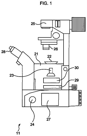
In this description

About 6,563 words. The USPTO PDF has it with every drawing.

Timeline & family

Timeline From USPTO dates

20122014201620182020202220242026Earliest priority dateJuly 14, 2011Application filedJuly 16, 2012Application publishedJuly 18, 2013Patent grantedJan 14, 20143.5-year fee paidJuly 14, 20177.5-year fee paidJuly 14, 202111.5-year fee not paidJuly 14, 2025Patent expiredJan 14, 2026

Maintenance fees

Fees are due 3.5, 7.5 and 11.5 years after grant. This patent expired on January 14, 2026, so the fee marked "not paid" was the one that went unpaid.

3.5-year feeDue July 14, 2017Paid
7.5-year feeDue July 14, 2021Paid
11.5-year feeDue July 14, 2025Not paid

US family 2 documents, by filing date

Published applicationUS 2013/0181143 A1

MICROSCOPY WITH ADAPTIVE OPTICS

Filed Jul 2012 · published Jul 2013
Published application
This documentUS 8,629,413 B2

Microscopy with adaptive optics

Filed Jul 2012 · granted Jan 2014
Lapsed, fee not paid

Earlier publications, parents and continuations. None of them can still be enforced, or this patent would not be listed.

Sources & verification

Verification

  • The USPTO Official Gazette of March 10, 2026 lists it as expired on January 14, 2026 for an unpaid maintenance fee.
  • It isn't on any reinstatement notice published since.
  • Its 1 US relative has also lapsed, expired or never issued.
  • Rechecked against USPTO records every day.
  • We check US rights only. Check foreign counterparts before selling abroad.

Confirm it yourself

  1. Open the file history on Patent Center.
  2. The status should read "Patent Expired Due to NonPayment of Maintenance Fees Under 37 CFR 1.362".
  3. Check the documents for any later petition to revive or reinstate.

Everything on this page comes from the documents linked above.

More in Cameras, Displays & Optics

All Cameras, Displays & Optics
Drawing from US 8,629,389 B2Lapsed, fee not paid46 drawings
Cameras, Displays & Optics · US 8,629,389 B2

Low profile camera and vision sensor

A monolithic camera configured for a predetermined environment can be made in the following manner.

Filed2009
LapsedJan 2026
OwnerSolo inventor
Drawing from US 8,629,862 B2Lapsed, fee not paid4 drawings
Cameras, Displays & Optics · US 8,629,862 B2

Display with pseudo photo sensor

A display capable of performing ambient light detection with a high accuracy is provided.

Filed2010
LapsedJan 2026
OwnerInnolux Corporation