Background
Modern computing devices often include a Trusted Platform Module (TPM) that provides security functionality to its host computing device. The TPM, being a hardware component, can provide for increased security over that available solely through the execution of computer-executable instructions by the computing device. More specifically, the hardware of a traditional TPM is designed to protect information stored within the TPM by enabling access and modification of such information only through specific channels and specific functions, and preventing other access or modification of such information. Thus, even if a malicious entity were to gain physical access to the TPM itself, the information stored within the TPM would still remain protected, except where truly exotic and advanced forensics were applied.
One set of information that is commonly stored in a TPM are the numerical values that are stored in a TPM's Platform Configuration Registers (PCRs). These numerical values are intended to represent a current state of the computing device and are generated by extending numerical values, representing a hardware or software component that is being instantiated, into various PCRs. Thus, starting with an initial value when the computing device is powered on, the PCRs are extended with numerical values that represent hardware or software components that are successively instantiated, such that the value of the PCRs at a given time represents the state of the computing device at that time, as defined by the hardware or software components that have been instantiated, and measured into the PCRs, up to that point in time.
As indicated, the hardware of the TPM is designed such that the values of the PCRs can only be changed by the above-described extending process. Thus, the values of the PCRs cannot otherwise be modified, nor can specific values simply be stored in them. However, this design works best if the state of the computing device is represented only by components that were instantiated since the computing device was last powered on.
To conserve power, however, some computing devices have the capability of entering a "sleep" state or an even less power consuming "hibernate" state. Typically, a sleep state comprises a computing device ceasing most processing operations, as well as turning off or powering down other power consuming peripherals, such as display devices or hard disk drives. However, in a sleep state, a computing device will typically utilize power to maintain the contents of volatile memory, as well as maintain the current state of the TPM and any information stored therein, such as the values of PCRs. Consequently, when resuming from a sleep state, the state of the computing device, as reflected by both contents of volatile memory and the values of the PCR's of the TPM, can remain unchanged from when the computing device entered the sleep state.
By contrast, to conserve as much power as possible, a hibernate state typically does not provide for continued power consumption by the volatile memory of the computing device, thereby resulting in the loss of the information that was stored in the volatile memory. To preserve the contents of volatile memory, a computing device entering the hibernate state can first save the contents of volatile memory to a non-volatile storage medium. Subsequently, the computing device can enter the hibernate state, which is typically a completely powered off state, akin to the computing device being completely shut down, with the exception that the contents of volatile memory are saved on a non-volatile storage medium.
Subsequently, to resume operation, the computing device can proceed through an initial boot sequence similar to being powered on or restarted, except that, at some point in time in the initial boot sequence, the contents of volatile memory that were saved to the non-volatile storage medium can be detected, and copied back into the volatile memory, thereby enabling the computing device to resume its pre-hibernation state. However, while the computing device can resume its pre-hibernation state, at least as far as the hardware and software that has been instantiated and for which computer-executable instructions and data can have been restored into volatile memory, the PCRs of the TPM may not necessarily comprise the values that are associated with the pre-hibernation state. In particular, the copying of the saved contents back into volatile memory typically does not extend the PCRs of the TPM in the same manner as they would have been extended were the state of the computing device re-created from an initial power on or restart sequence. Consequently, the values of the PCRs may no longer correlate with the state of the computing device.
Summary
In one embodiment, prior to entering a hibernation state, the current values of the Platform Configuration Registers (PCRs) can be quoted, such as by being signed with keys unique to a trusted execution environment, such as a Trusted Platform Module (TPM), and the values of the PCRs, together with the quote, can be appended to an event log that is typically maintained in volatile memory. When the contents of volatile memory are saved to a non-volatile storage medium, as is typically performed by a computing device prior to entering the hibernation state, the event log with the current values of the PCRs, and a quote thereof, can be part of the information that is saved to the non-volatile storage medium.
In another embodiment, a monotonic counter that can only be incremented and cannot be reset, such as can be typically maintained by trusted execution environments, can be utilized as a "boot counter", and can be incremented each time a computing device is "booted". The current value of the monotonic counter can be appended to the event log, along with the values of the PCRs, and the quote thereof, prior to the computing device entering the hibernation state.
In a further embodiment, upon a subsequent resuming from a hibernated state, an existing event log can be concatenated with the event log that had been saved to the non-volatile storage medium as part of the hibernation process. The resulting event log, that can be maintained in volatile memory, and appended to in a traditional manner, can comprise not only entries since the most recent resuming from the hibernated state, but also entries prior to hibernation, including the values of the PCRs prior to hibernation, the quote thereof and the value of the monotonic counter prior to hibernation.
In a still further embodiment, an event log comprising events from multiple generations or incarnations of a computing device, such as events from prior to a hibernation of the computing device and events subsequent to a resuming from hibernation, can be evaluated with reference to the current PCR values, the prior PCR values, as saved and quoted in the event log, and with reference to an incremental continuity between the current value of the monotonic counter and saved values of the monotonic counter in the event log.
This Summary is provided to introduce a selection of concepts in a simplified form that are further described below in the Detailed Description. This Summary is not intended to identify access control features or essential features of the claimed subject matter, nor is it intended to be used to limit the scope of the claimed subject matter.
Additional features and advantages will be made apparent from the following detailed description that proceeds with reference to the accompanying drawings.
Description of the drawings
The following detailed description may be best understood when taken in conjunction with the accompanying drawings, of which:
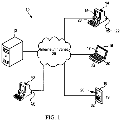
FIG. 1 is a diagram of an exemplary computing device comprising a TPM;
FIG. 2 is a block diagram of an exemplary operation of a computing device after a power on;
FIG. 3 is a block diagram of an exemplary operation of a computing device prior to a hibernate;
FIG. 4 is a block diagram of an exemplary operation of a computing device after a resume from hibernation;
FIG. 5 is a block diagram of a further exemplary operation of a computing device after a resume from hibernation;
FIG. 6 is a block diagram of an exemplary examination of an event log;
FIG. 7 is a flow diagram of an exemplary operation of a hibernation-capable computing device; and
FIG. 8 is a flow diagram of an exemplary examination of an event log.
Detailed description
The following description relates to the logging, into an event log, of the values of at least some of the Platform Configuration Registers (PCRs) of a trusted execution environment, together with the value of a monotonic counter of the trusted execution environment that is being used as a boot counter, prior to the hibernation of the computing device comprising the trusted execution environment. Upon a subsequent resume, the prior event log into which this information was entered, which was saved as part of the hibernation image, can be concatenated with a current event log, thereby providing a mechanism with which to securely record the history of the computing device, at least since the most recent power on or restart.
The mechanisms described herein focus on, but are not limited to, physical computing devices entering a low power "hibernation" mode or state. Indeed, the teachings below are equally applicable to virtual computing devices that emulate the operation of a physical computing device, and can be applied, not merely across hibernate-and-resume cycles, but across any cycle in which the state of a computing device is restored without being recreated, including, for example, the distribution of state to otherwise stateless, terminal computing devices, and other like environments. As a result, the specific exemplary circumstances referenced are utilized to render the descriptions more concrete and are not meant to limit the enumerated embodiments to the specific exemplary circumstances referenced.
Additionally, the mechanisms described herein are often described with reference to a Trusted Platform Module (TPM) because such a module is well known in the art and comprises attributes that can be utilized by the mechanisms described below. However, as will be recognized by those skilled in the art, TPMs traditionally must conform to the Trusted Computing Group's (TCG's) standards and requirements for such a module and, as such, comprise features and functionality that are useless, or, at best, orthogonal to the mechanisms described herein. Thus, while reference is made to TPMs for purposes of descriptional clarity, the mechanisms described herein are equally applicable to any "trusted execution environment" that can securely provide the requisite functionality, such as a secure monotonic counter, one or more platform configuration registers that can only be modified in defined ways according to the components being instantiated by a computing device, and the ability to sign or quote information with reference to one or more securely maintained and obtained cryptographic keys. As utilized herein, the term "trusted execution environment" is meant to encompass a physical TPM conforming to the TCG standards, as well as other hardware or software modules that can securely provide the requisite functionality, such as that enumerated above and described in more detail below.
Although not required, the description below will be in the general context of computer-executable instructions, such as program modules, being executed by a computing device. More specifically, the description will reference acts and symbolic representations of operations that are performed by one or more computing devices or peripherals, unless indicated otherwise. As such, it will be understood that such acts and operations, which are at times referred to as being computer-executed, include the manipulation by a processing unit of electrical signals representing data in a structured form. This manipulation transforms the data or maintains it at locations in memory, which reconfigures or otherwise alters the operation of the computing device or peripherals in a manner well understood by those skilled in the art. The data structures where data is maintained are physical locations that have particular properties defined by the format of the data.
Generally, program modules include routines, programs, objects, components, data structures, and the like that perform particular tasks or implement particular abstract data types. Moreover, those skilled in the art will appreciate that the computing devices need not be limited to conventional personal computers, and include other computing configurations, including hand-held devices, multi-processor systems, microprocessor based or programmable consumer electronics, network PCs, minicomputers, mainframe computers, and the like. Similarly, the computing devices need not be limited to a stand-alone computing device, as the mechanisms may also be practiced in distributed computing environments linked through a communications network. In a distributed computing environment, program modules may be located in both local and remote memory storage devices.
With reference to FIG. 1, an exemplary computing device 100 is illustrated, comprising, in part, hardware elements referenced further in the methods described below. The exemplary computing device 100 can include, but is not limited to, one or more central processing units (CPUs) 120, a system memory 130, a Trusted Platform Module (TPM) 150, and a system bus 121 that couples various system components including the system memory to the processing unit 120. The system bus 121 may be any of several types of bus structures including a memory bus or memory controller, a peripheral bus, and a local bus using any of a variety of bus architectures. Depending on the specific physical implementation, one or more of the CPUs 120, the system memory 130 and the TPM 150 can be physically co-located, such as on a single chip. In such a case, some or all of the system bus 121 can be nothing more than silicon pathways within a single chip structure and its illustration in FIG. 1 can be nothing more than notational convenience for the purpose of illustration.
As indicated previously, the mechanisms described herein are equally applicable to any trusted execution environment, and a hardware TPM, such as the TPM 150 shown in FIG. 1, is but one example of such a trusted execution environment. Thus, utilization of the TPM 150, described below, is not intended to limit the mechanisms described to specifically hardware TPMs conforming to the TCG specifications and is, instead intended to illustrate the mechanisms described within a specific context that can be trivially expanded to any trusted execution environment. Thus, strictly for ease of illustration, references will be made to the TPM 150 shown in FIG. 1. The TPM 150 can comprise TPM-specific keys 151 for the encryption and decryption of information provided to it. Traditionally, the TPM 150 comprises an initial set of immutable public and private encryption keys that can be utilized, in a known and established manner, to obtain disposable public and private encryption keys. For example, the TPM 150 can comprise public and private portions of an Endorsement Key (EK), one or more Attestation Identity Keys (AIKs), and other like cryptographic keys that can be utilized to variously sign, quote and encrypt and decrypt information. In addition, the TPM 150 can comprise Platform Configuration Registers (PCRs) 155 that can securely store values or other data uniquely associated with the state of the computing device 100. Such values are traditionally provided to the TPM 150 by the CPU 120 via the system bus 121. In some embodiments, only specific code executed by the CPU 120 would be permitted to send data to the TPM 150 that would modify the values stored in the PCRs 155. The TPM 150 can further comprise at least one monotonic counter, such as the monotonic counter 156. The value stored by the monotonic counter 156 can be incremented, but not decremented or assigned a specific value, as such actions can be prevented by the TPM 150. In one embodiment, once the value of the monotonic counter 156 exceeds a certain threshold, it can roll over to an initial value and can be incremented further from there.
In addition to the elements described above, the computing device 100 also typically includes computer readable media, which can include any available media that can be accessed by the computing device 100. By way of example, and not limitation, computer readable media may comprise computer storage media and communication media. Computer storage media includes media implemented in any method or technology for storage of information such as computer readable instructions, data structures, program modules or other data. Computer storage media includes, but is not limited to, RAM, ROM, EEPROM, flash memory or other memory technology, CD-ROM, digital versatile disks (DVD) or other optical disk storage, magnetic cassettes, magnetic tape, magnetic disk storage or other magnetic storage devices, or any other medium which can be used to store the desired information and which can be accessed by the computing device 100. Communication media typically embodies computer readable instructions, data structures, program modules or other data in a modulated data signal such as a carrier wave or other transport mechanism and includes any information delivery media. By way of example, and not limitation, communication media includes wired media such as a wired network or direct-wired connection, and wireless media such as acoustic, RF, infrared and other wireless media. Combinations of the any of the above should also be included within the scope of computer readable media.
When using communication media, the computing device 100 may operate in a networked environment via logical connections to one or more remote computers. The logical connection depicted in FIG. 1 is a general network connection 171 to a network 180 that can be a local area network (LAN), a wide area network (WAN) or other networks. The computing device 100 is connected to the general network connection 171 through a network interface or adapter 170 which is, in turn, connected to the system bus 121. In a networked environment, program modules depicted relative to the computing device 100, or portions or peripherals thereof, may be stored in the memory of one or more other computing devices that are communicatively coupled to the computing device 100 through the general network connection 171. It will be appreciated that the network connections shown are exemplary and other means of establishing a communications link between computing devices may be used.
Among computer storage media, the system memory 130 comprises computer storage media in the form of volatile and/or nonvolatile memory, including Read Only Memory (ROM) 131 and Random Access Memory (RAM) 132. A Basic Input/Output System 133 (BIOS), containing, among other things, code for booting the computing device 100, is typically stored in ROM 131. RAM 132 typically contains data and/or program modules that are immediately accessible to and/or presently being operated on by the processing unit 120. By way of example, and not limitation, FIG. 1 illustrates operating system 134, other program modules 135, and program data 136 as being resident in the RAM 132. The RAM 132 can also comprise data that can be relevant to the operation of the TPM 150, such as the event log 190. In one embodiment, the event log 190 can comprise a unique identification of all of the modules loaded or executed by the computing device 100 since power was applied or since it was last restarted; the same modules whose loading or execution can have resulted in the values currently maintained by the TPM 150 in one or more PCRs 155. For example, the event log 190 can be a Trusted Computing Group (TCG) event log.
The computing device 100 may additionally include other removable/non-removable, volatile/nonvolatile computer storage media. By way of example only, FIG. 1 illustrates a hard disk drive 141 that reads from or writes to non-removable, non-volatile magnetic or solid-state media. Other removable/non-removable, volatile/nonvolatile computer storage media that can be used with the exemplary computing device include, but are not limited to, solid-state based storage devices, magnetic tape cassettes, flash memory cards, digital versatile disks, digital video tape, solid state RAM, solid state ROM, and the like. The hard disk drive 141 is typically connected to the system bus 121 through a non-removable memory interface such as interface 140.
The drives and their associated computer storage media discussed above and illustrated in FIG. 1, provide storage of computer readable instructions, data structures, program modules and other data for the computing device 100. In FIG. 1, for example, hard disk drive 141 is illustrated as storing operating system 144, other program modules 145 and program data 146. Note that these components can either be the same as or different from operating system 134, other program modules 135 and program data 136. Operating system 144, other program modules 145 and program data 146 are given different numbers hereto illustrate that, at a minimum, they are different copies.
In one embodiment, the "state" of the computing device 100 can be defined by the hardware components, such as those described above, and the components of computer-executable instructions, also such as those described above, that have been instantiated, or otherwise activated, since the computing device 100 was powered on or restarted. From a security perspective, the state of the computing device 100 at a time prior to the application of power and prior to the initialization of any hardware, or the execution of any computer-executable instructions, can be regarded as a "safe" state. Consequently, from a security perspective, whether any subsequent state of the computing device 100 is secure can be determined via examination of the changes made to the computing device 100 from the moment when power was applied, or reapplied after a restart. Thus, as will be known by those skilled in the art, one function of the event log 190 is to provide a record of all of the relevant hardware components and components of computer-executable instructions that have been instantiated on the computing device 100 since power was applied. If each of the elements listed in the event log 190 are believed to be safe, then the current state of the computing device 100 can likewise be deemed to be safe, since the computing device can be deemed to have not departed from its initial safe state. Conversely, and more practically, if any one of the elements listed in the event log 190 is believed to be a security concern, then the state of the computing device 100 can be determined to no longer be safe and, as a result, the computing device 100 can be prevented from performing certain security-sensitive operations, such as, for example, joining a secure network, or accessing protected data.
However, as will also be known by those skilled in the art, the event log 190, being retained in the RAM 132, can be accessed and modified and, as a result, cannot be assured to be an accurate representation of all of the relevant hardware components and components of computer-executable instructions that have been instantiated on the computing device 100 since power was applied. To protect against such tampering of the event log 190, the PCRs 155 of the TPM 150 are utilized to retain values associated with the entries in the event log 190 such that if the values of the PCRs 155 do not correspond to the entries in the event log 190, a determination can be made that the event log 190 may have been tampered with and no longer represents an accurate listing of the relevant hardware components and components of computer-executable instructions that have been instantiated on the computing device 100 since power was applied. In particular, and as will also be known to those skilled in the art, each entry in the event log 190 can correspond to a particular hardware component or components of computer-executable instructions that can be measured, such as by computing a hash of the relevant-computer executable instructions, or otherwise deriving a unique numerical value that represents that component. As each component is instantiated, this unique numerical value can be extended into one or more of the PCRs 155 via known mathematical operations that receive, as input, the prior value of the one or more PCRs 155 and the unique numerical value that is being extended into them, and derive therefrom a subsequent numerical value that is stored back into the one or more PCRs 155. Consequently, the current value of the PCRs 155 should be obtainable by performing such an extend operation with the unique numerical values associated with each of the entries in the event log 190, in the order of those entries in the event log 190. If the values obtained from the entries in the event log 190 do not match those maintained in the PCRs 155, the above conclusion that the event log 190 is no longer accurate can be reached.
Turning to FIG. 2, the system 200 shown therein illustrates an exemplary series of operations in accordance with the above descriptions, that also provide a foundation for the descriptions below. As can be seen from the system 200, a power on event 210 can be applied to the computing device 100, thereby causing the computing device 100 to commence initializing, or otherwise instantiating, various hardware components, and also to commence executing computer-executable instructions, such as the operating system 144 that is stored on the hard disk drive 141 of the computing device 100. For example, as shown in the system 200 of FIG. 2, the operating system 144, that is stored on the hard disk drive 141, can be booted, or otherwise instantiated, as illustrated by the boot action 230. As will be understood by those skilled in the art, the process of instantiating the operating system 144 can result in the creation of the operating system 134 as an executing process that stores information in the RAM 132. Consequently, the boot action 230 is illustrated in FIG. 2 as transferring information from the operating system 144, as stored on the hard disk drive 141, to the RAM 132, in the form of the operating system 134, which is illustrated in gray to indicate that, as of the commencement of the boot action 230, the operating system 134 does not yet fully exist within the RAM 132.
As each component of the computing device 100 is instantiated, an appropriate entry can be added to the event log 190. Thus, as illustrated by the log action 232, shown in the system 200 of FIG. 2, entries for the instantiation of the operating system 144, such as the exemplary OS loader entry 292 and the exemplary operating system entry 293 can be added to the event log 190. In one embodiment, such entries 292 and 293 can be added either before or after the entries for the hardware that was instantiated prior to the operating system 144, such as the hardware entry 291, depending on whether the event log 190 is organized in a first-on-top or a first-on-bottom order. As will be recognized by those skilled in the art, typical entries in an event log 190 can comprise more detail, and can be more finely delineated. However, the entries 291, 292 and 293 are shown in the event log 190 purely for illustrative purposes.
In addition to the logging action 232, the instantiation of the operating system 144 can result in one or more extend operations, such as the extend action 231, that can extend one or more of the PCRs 155 with measurement values of some or all of the components of the operating system 144 that correspond to the entries 292 and 293 in the event log 190. In such a manner, the computing device 100 can proceed through its booting sequence and can, optionally, instantiate further computer executable instructions, such as those that comprise program modules 145, including logging the appropriate entries in the event log 190 and extending one or more of the PCRs 155 with appropriate measurement values.
In one embodiment, a monotonic counter 156 of the trusted platform module 150 can be utilized as a "boot counter" such that it can be incremented, as indicated by the increment action 220, each time the computing device 100 is booted, including, for example, being powered on, such as illustrated in the system 200 of FIG. 2, being restarted, or being resumed from hibernate state. As utilized herein, the term "powered on" means the application of power to a computing device after an extended period of time in a mechanical power off state, such as that defined as the "G3" state in the Advanced Configuration and Power Interface (ACPI) specification. Conversely, the term "restart", as utilized herein, means the application of power to a computing device as part of an automated cycle through a power off state, such as can be initiated by selecting a "restart" option common in many operating systems. The term "resume", as utilized herein, means the application of power after a computing device has entered a hibernation state, such as that defined by the "S4" state of the ACPI specification. Returning back to FIG. 2, the value 256 of the monotonic counter 156 can be an increment greater than the prior value, represented by the variable "x" in the figure, to account for the illustrated booting of the computing device 100. Additionally, while the illustration in FIG. 2 shows an increment step of one, other incrementation values can be utilized.
Turning to FIG. 3, the system 300 shown therein illustrates the computing device in a state after it has been booted and utilized. Thus, in the illustrated example shown in FIG. 3, the event log 190 can comprise further entries to those described previously including, for example, entry 394 referencing one or more program modules, or other components of computer-executable instructions.
As shown in the system 300 of FIG. 3, a hibernate instruction 310 can be provided to the computing device 100 that can cause the computing device to store the contents of the RAM 132, or at least some portion thereof, on a volatile storage medium, such as the hard disk drive 141, as a hibernation image, such as the hibernation image 360. Such an action is represented by the store action 350 in FIG. 3.
In one embodiment, prior to creating the hibernation image 360, one or more additional entries can be logged into the event log 190. In particular, as illustrated by the quote action 320, one or more of the TPM-specific keys 151 can be utilized in a manner well known to those skilled in the art to quote the current values of one or more of the PCRs 155. For example, an AIK can be utilized to sign the values of one or more of the PCRs 155. Such a process can prove that the values of the one or more PCRs 155 that are quoted were, in fact, in existence on the computing device 100 at the time that they were quoted.
Subsequently, as illustrated by the logging action 321, this quote of the PCRs 155 can be appended to the event log 190 as illustrated by the entry 395. In addition, the entry 395 can further comprise the values of the PCRs 155 themselves, as illustrated by the logging action 330, such that the quote provides proof that the values of the PCRs 155 that are part of the entry 395 have not been tampered with or otherwise modified. In one embodiment, the entry 395 can further comprise the current value 256 of the monotonic counter 156, as illustrated by the logging action 340. As will be recognized by those skilled in the art, while the values of the PCRs 155, the quote of the values of the PCRs 155 and the value 256 of the monotonic counter 156 are shown in FIG. 3 as being logged into the event log 190 as a single entry 395, such an illustration is merely an example and is simplified for illustrative clarity. In other embodiments, one or more of those pieces of information can be logged individually or via multiple entries in the event log 190.
The logging actions 321, 330 and 340 can occur prior to the creation of the hibernation image 360, by the store action 350. As a result, the entry 395 can be part of the event log 190 when the event log 190 is saved on a non-volatile storage medium, such as the hard disk drive 141, in the hibernation image 360. As will be known by those skilled in the art, once the hibernation image 360 has been saved, and the computing device 100 has performed other relevant hibernation-centric functions, it can proceed to hibernate, and the contents of the RAM 132 can be lost as the computing device 100 can enter, essentially, a powered off state. While the logging actions 321, 330 and 340 are shown as occurring within the context of a hibernation of the computing device 100, they need not occur temporally close to such a hibernation event. For example, in one embodiment, the logging actions 321, 330 and 340 can be performed at any time during the operation of the computing device 100 including, for example, soon after the computing device 100 has completed booting.
Turning to FIG. 4, the system 400 shown therein illustrates the computing device 100, comprising the hibernation image 360, being resumed from a hibernated state. Initially, a resume action 410, can be applied to the computing device 100 by, for example, depressing a power button or other like user action. Subsequently, the computing device 100 can proceed through a boot sequence analogous to that described above with reference to the system 200 of FIG. 2. Thus, as shown in the system 400 of FIG. 4, the operating system 144 can be booted, as illustrated by the boot action 430, to generate an in-memory operating system 134, and the relevant components of the operating system can both be logged into the event log 190, as illustrated by the logging action 432, and their measurements can be extended into one or more of the PCRs 155, as illustrated by the extend action 431. In addition, as also described previously, the monotonic counter 156 can be incremented, as shown by the increment action 420 in the system 400 of FIG. 4. The resulting value 456 of the monotonic counter 156 can be a single increment unit greater than the prior value 256 of the monotonic counter 156.
Typically, however, once an OS loader, or other relevant component of the operating system 134, detects the presence of the hibernation image 360, the traditional booting of the computing device 100 can be suspended, and the hibernation image 360 can be restored to the RAM 132. Thus, as shown in the system 400 of FIG. 4, the event log 190 may not comprise anything more than entries for the instantiated hardware, such as the entry 496, and entries for the OS loader, or other relevant components of the operating system 134, such as the entry 497, before the hibernation image 360 is restored to the RAM 132.
Turning to FIG. 5, system 500 shown therein illustrates one exemplary restoring of the hibernation image 360 to the RAM 132. As illustrated by the restore action 550, the restoring of the hibernation image 360 to the RAM 132 can return, to the RAM 132, the operating system 134, the program modules 135 and the program data 136 that were previously stored thereon prior to the hibernation of the computing device 100. As will be recognized by those skilled in the art, the restoring of the contents of RAM 132 can enable the computing device 100 to recommence with the operations that it was performing prior to being hibernated. However, as will also be recognized by those skilled in the art, the restore action 550 may not affect the PCRs 155. Thus, the values of the PCRs 155 may reflect, for example, the state of the computing device 100 immediately prior to the restoring of the hibernation image 360, as opposed to the actual state of the computing device, which is more analogous to that shown in the system 300 of FIG. 3.
However, as part of the restore operation 550, the event log 190 can be modified to comprise both the information that was in the event log 190 as it was saved in the hibernation image 360 and is now being restored to RAM 132, such as the entries 291, 292, 293, 394 and 395, and to further comprise information that was added to the event log 190 since the most recent powering on of the computing device 100 to resume it from the hibernated state, such as the entries 496 and 497.
As such, the event log 190 can comprise sufficient information to accurately assess the security state of the computing device 100. In particular, the components that were previously instantiated, and which impacted the state of the computing device 100 prior to hibernation, which was now restored, can be represented in the event log 190, such as via the entries 291, 292, 293 and 394. Additionally, the components that were currently instantiated, and which can impact the current state of the computing device, can likewise be represented in the event log 190, such as via the entries 496 and 497. The current entries of the event log 190 can be validated with reference to the current value of one or more PCRs 155, in a manner known to those skilled in the art, while the prior entries of the event log 190 can be validated with reference to the prior value of one or more PCRs 155 that were stored into the event log 190, such as part of the entry 395. The quote of that prior value of one or more PCRs 155 can be utilized to ensure that the values stored in the event log 190 had not been modified.
In addition, a comparison between the current value 456 of the monotonic counter 156 and one or more prior values 256 of the monotonic counter 156, such as those that can be part of the entry 395, can reveal if the computing device was booted in the interim without appropriate information being logged to the event log 190. For example, if the prior value 256 of the monotonic counter 156 that is part of the entry 395 is incrementally continuous with the current value 456 of the monotonic counter 156, then a determination can be made that the computing device was not otherwise booted between the prior boot, which resulted in the state of the computing device that was hibernated, and the current boot, which resulted in that state being resumed.
Turning to FIG. 6, the system 600 shown therein illustrates one exemplary utilization of the above described mechanisms. In the system 600 of FIG. 6, the personal computing device 610 can be a computing device that has gone through a similar sequence of steps to those described in detail above with reference to the exemplary computing device 100. As such, the personal computing device 610 can comprise the event log 190, the PCRs 155 and the monotonic counter 156. Additionally, the gateway computing device 620 can likewise share the general hardware and software described with reference to the exemplary computing device 100, such as with reference to FIG. 1.
The description continues in the full USPTO document.
 Lapsed, fee not paid37 drawings

