Field of embodiments of the invention
Some applications of the present invention generally relate to implanted medical apparatus. Specifically, some applications of the present invention relate to apparatus and methods for treating congestive heart failure, diastolic heart failure, hypertension, and/or other conditions.
Background
Heart failure is a condition in which a problem with the structure or function of the heart impairs its ability to supply sufficient blood flow to meet the body's needs. The condition impairs quality of life and is a leading cause of hospitalizations and mortality in the western world. Treatment of heart failure is typically aimed at removal of precipitating causes, prevention of deterioration in cardiac function, and control of congestive state.
Hypertension, or chronic high blood pressure, is an extremely prevalent medical condition, which can lead to strokes, heart attacks, and heart failure. There are a variety of treatments that are available for treating hypertension, including lifestyle changes, and medication.
Summary of embodiments
For some applications of the invention a subject suffering from congestive heart failure, diastolic heart failure, hypertension, and/or another condition is identified. The subject is treated by implanting an electrode on the subject's vagus nerve at a vagal site that is between (a) the vagal bifurcation with the thoracic cardiac branch, and (b) the thoracic vagal branching into the esophageal plexus. Alternatively or additionally, an electrode is implanted in the vicinity of (i.e., inside, within the wall of, or outside of) the subject's aorta, at an aortic site that is between the bifurcations of the aorta with the first and fifth intercostal arteries. The subject is treated by driving a current into the electrode implantation site. The effects of driving the current into the implantation site typically include ventricular and aortic pressure reduction, an increase in aortic compliance, a decrease in sympathetic tone, and/or an increase in parasympathetic tone. These effects are typically advantageous in treating heart failure.
For some applications of the present invention, a sensing electrode is implanted in the vicinity of a non-coronary blood vessel of a subject, for example, in the vicinity of an artery, such as the subject's aorta. The sensing electrode detects an electrical parameter of the blood vessel (e.g., the aorta), and a control unit receives the detected parameter and generates an output in response to the detected parameter.
For some applications, the electrode is implanted at a site that is between 20 mm and 50 mm downstream from an aortic valve of the subject.
The electrical parameter that the sensing electrode detects is typically indicative of the subject's cardiac cycle. Thus, for some applications, cardiac-cycle-derivation functionality of the control unit detects the subject's cardiac cycle, and/or a timing parameter of the subject's blood pressure by analyzing the detected parameter. Typically, treatment functionality of the control unit generates an output, responsively to the detected parameter. For example, the treatment functionality may generate an electrical stimulus (e.g., to stimulate a blood vessel of the subject) in response to the detected parameter. Or, the treatment functionality may generate a mechanical stimulus (e.g., a pressure change at the subject's aorta for causing counterpulsation, or afterload reduction), responsively to the detected parameter. For some applications, the treatment functionality generates the mechanical stimulus using a pressure applicator, such as an intra-aortic balloon.
For some applications, the sensing electrode is placed at a first location in the vicinity of a non-coronary blood vessel of the subject, and the control unit generates an output that has an effect at (or in the vicinity of) the first location. For example, the sensing electrode may be placed on an artery that supplies the subject's penis, such as the internal pudendal artery. In response to the detected parameter, the control unit drives an electrode (e.g., the sensing electrode or a different electrode) to drive a current into the internal pudendal artery. Alternatively or additionally, the sensing electrode is placed at a first location in the vicinity of a first non-coronary blood vessel of the subject, and the control unit generates an output that has an effect at a second location within the subject's body (e.g., a location in the vicinity of a second non-coronary blood vessel). For example, the sensing electrode may be placed on the subject's aorta, and in response to the detected parameter, the control unit drives an electrode to drive a current into the subject's internal pudendal artery.
For some applications, the control unit drives a current into the aorta in response to the detected parameter. For some applications, the control unit drives the current in coordination with the subject's cardiac cycle. For example, the subject's cardiac cycle may be determined by analyzing the detected parameter, as described hereinabove. Alternatively, the cardiac cycle is detected using an ECG, and/or by taking impedance measurements, for example, using the Cheetah Reliant, described hereinabove and/or similar technology. For example, in response to detecting systole of the subject, the control unit may dilate the aorta by increasing nitric oxide (NO) secretion by the wall of the aorta by driving the current. Alternatively or additionally, in response to detecting diastole of the subject, the control unit enhances constriction of the aorta by driving the current.
For some applications of the present invention, two, or more electrodes are implanted in a vicinity of an aorta of a subject. A control unit peristaltically pumps blood through the aorta by sequentially dilating portions of the aorta by facilitating nitric oxide production by the aorta by driving a current into the aorta via the electrodes. For some applications, the control unit peristaltically pumps blood through a different blood vessel of the subject, in the aforementioned manner. For example, the control unit may peristaltically pump blood through any artery, such as a renal artery or a carotid artery, or through a vein of the subject.
For some applications, the control unit receives an indication of the subject's cardiac cycle (e.g., using techniques described herein), and drives the current in coordination with the subject's cardiac cycle. Typically, the control unit peristaltically pumps blood through the aorta during systole of the subject. For some applications, during diastole of the subject, the control unit does not peristaltically pump blood through the aorta, and/or the control unit enhances constriction of the aorta by driving a diastolic current into the aorta via the electrodes.
There is therefore provided, in accordance with some applications of the present invention, a method, including:
identifying a subject as suffering from a condition selected from the group consisting of congestive heart failure, diastolic heart failure, and hypertension; and
in response to the identifying: placing an electrode on a vagus nerve of the subject at a vagal site that is between (a) a vagal bifurcation with a thoracic cardiac branch of the subject, and (b) thoracic vagal branching into the esophageal plexus of the subject; and treating the subject by driving a current into the vagal site, via the electrode.
For some applications, placing the electrode at the vagal site includes placing the electrode on a portion of the vagus nerve that is adjacent to a portion of an aorta of the subject that is between first and fifth intercostal arteries of the subject.
For some applications, treating the subject includes reducing ventricular pressure of the subject.
For some applications, treating the subject includes reducing aortic pressure of the subject.
For some applications, treating the subject includes reducing sympathetic tone of the subject.
For some applications, treating the subject includes increasing parasympathetic tone of the subject.
For some applications, treating the subject includes increasing aortic compliance of the subject.
For some applications, the method further includes, in response to the identifying:
placing an electrode on an aorta of the subject at an aortic site that is between first and fifth intercostal arteries of the subject; and
treating the subject by driving a current into the aortic site, via the electrode.
For some applications, treating the subject includes increasing parasympathetic tone of the subject and reducing sympathetic tone of the subject.
For some applications, treating the subject includes reducing a ratio of a low frequency component to a high frequency component of heart rate variability of the subject.
For some applications, the low frequency component is less than 0.05 Hz, and the high frequency component is between 0.15 and 0.35 Hz.
For some applications, treating the subject includes reducing a ratio of a low frequency component to a high frequency component of heart rate variability of the subject.
For some applications, the low frequency component is less than 0.05 Hz, and the high frequency component is between 0.15 and 0.35 Hz.
There is further provided, in accordance with some applications of the present invention, a method, including:
identifying a subject as suffering from a condition selected from the group consisting of congestive heart failure, diastolic heart failure, and hypertension; and
in response to the identifying: placing an electrode on an aorta of the subject at an aortic site that is between first and fifth intercostal arteries of the subject; and treating the subject by driving a current into the aortic site, via the electrode.
For some applications, placing the electrode at the aortic site includes placing the electrode on a portion of the aorta that is adjacent to a portion of a vagus nerve of the subject that is between (a) a vagal bifurcation with a thoracic cardiac branch of the subject, and (b) thoracic vagal branching into the esophageal plexus of the subject.
For some applications, treating the subject includes reducing ventricular pressure of the subject.
For some applications, treating the subject includes reducing aortic pressure of the subject.
For some applications, treating the subject includes reducing sympathetic tone of the subject.
For some applications, treating the subject includes increasing parasympathetic tone of the subject.
For some applications, treating the subject includes increasing aortic compliance of the subject.
For some applications, placing the electrode on the aorta includes assessing a response of the subject to placement of the electrode at a plurality of sites, and implanting the electrode at the aortic site in response to the assessing.
For some applications, treating the subject includes increasing parasympathetic tone of the subject and reducing sympathetic tone of the subject.
For some applications, treating the subject includes reducing a ratio of a low frequency component to a high frequency component of heart rate variability of the subject.
For some applications, the low frequency component is less than 0.05 Hz, and the high frequency component is between 0.15 and 0.35 Hz.
For some applications, treating the subject includes reducing a ratio of a low frequency component to a high frequency component of heart rate variability of the subject.
For some applications, the low frequency component is less than 0.05 Hz, and the high frequency component is between 0.15 and 0.35 Hz.
There is further provided, in accordance with some applications of the present invention, a method for use with one or more non-coronary blood vessels of a subject, and a body of a subject, including:
at a first location in a vicinity of one of the blood vessels, detecting an electric signal that is indicative of electrical activity at the first location due to a cardiac cycle of the subject; and
responsively thereto, generating an output at a location selected from the group consisting of: the first location, and a second location within the subject's body that is different from the first location.
For some applications, the selected location includes the first location, and generating the output includes generating the output at the first location.
For some applications, the selected location includes the second location, and generating the output includes generating the output at the second location.
For some applications, generating the output includes applying pressure to the selected location.
For some applications, the selected location includes an aorta of the subject, and applying the pressure includes counterpulsating the aorta by applying the pressure.
For some applications, the selected location includes an aorta of the subject, and applying the pressure includes reducing afterload of the subject by applying the pressure.
For some applications, generating the output includes driving a current into the selected location.
For some applications, the method further includes identifying the subject as suffering from erectile dysfunction, the selected location includes an artery of the subject that supplies a penis of the subject, and applying the electrical stimulation to the selected location includes, responsively to identifying the subject as suffering from the erectile dysfunction, treating the erectile dysfunction of the subject.
For some applications, detecting the signal includes detecting the signal at an aorta of the subject.
For some applications, detecting the signal includes detecting the signal at the artery that supplies the penis.
There is additionally provided, in accordance with some applications of the present invention, apparatus for use with one or more non-coronary blood vessels of a subject, and a body of a subject, including:
an electrode configured to be placed at a first location in a vicinity of one of the blood vessels, and to detect an electrical signal of the blood vessel;
cardiac-cycle-derivation functionality configured to derive from the signal a current phase of a cardiac cycle of the subject; and
treatment functionality configured, responsively to the derived phase, to generate an output at a location selected from the group consisting of: the first location, and a second location within the subject's body that is different from the first location.
For some applications, the apparatus further includes a pressure-applicator, and the treatment functionality is configured to generate the output by causing the pressure applicator to apply pressure to the selected location.
There is further provided, in accordance with some applications of the present invention, apparatus, including:
an electrode configured to be placed in contact with an artery of a subject;
a control unit configured to drive the electrode to perform a function with respect to the artery, the function selected from the group consisting of: driving a current into the artery, and sensing an electrical parameter of the artery; and
a transmitter configured to be placed in a vein of the subject that is in a vicinity of the artery, the transmitter being wiredly connected to the control unit, and the control unit being configured to drive the electrode by wirelessly transmitting a signal via the transmitter.
For some applications, the control unit is configured to be subcutaneously implanted inside the subject.
For some applications, the transmitter includes a coil that defines a plane, and the coil is configured to be placed inside the subject's vein such that the plane defined by the coil is at an angle of more than 10 degrees from a plane that is perpendicular to a local longitudinal axis of the vein.
For some applications, the apparatus further includes a coil support structure, the coil being coupled to the support structure such that the support structure is configured to place the coil inside the subject's vein such that the plane defined by the coil is at the angle of more than 10 degrees from the plane that is perpendicular to the local longitudinal axis of the vein.
For some applications, the transmitter is configured to be placed in a subclavian vein of the subject, and the electrode is configured to be placed in contact with an aorta of the subject.
For some applications, the electrode is configured to be placed in contact with an aortic site that is between first and fifth intercostal arteries of the subject.
For some applications, the transmitter is configured to be placed in the vein such that the transmitter is at a distance of less than 20 mm from the electrode.
For some applications, the transmitter is configured to be placed in the vein such that the transmitter is at a distance of less than 5 mm from the electrode.
There is additionally provided, in accordance with some applications of the present invention, a method, including:
placing an electrode in contact with an artery of a subject;
placing in a vein of the subject that is in a vicinity of the artery, a transmitter that is wiredly connected to a control unit; and
using the control unit, driving the electrode to perform a function with respect to the artery, the function selected from the group consisting of: driving a current into the artery, and sensing an electrical parameter of the artery,
the driving being performed by the control unit wirelessly transmitting a signal via the transmitter.
For some applications, placing the transmitter inside the vein includes placing the transmitter inside a subclavian vein of the subject, and placing the electrode in contact with the artery includes placing the electrode in contact with an aorta of the subject.
For some applications, placing the electrode in contact with aorta includes placing the electrode in contact with an aortic site that is between first and fifth intercostal arteries of the subject.
For some applications, placing the electrode in contact with the aortic site includes placing the electrode in contact with a portion of the aorta that is adjacent to a portion of a vagus nerve of the subject that is between (a) a vagal bifurcation with a thoracic cardiac branch of the subject, and (b) thoracic vagal branching into the esophageal plexus of the subject.
For some applications, driving the electrode to perform the function with respect to the artery includes reducing ventricular pressure of the subject by driving a current into the aortic site via the electrode.
For some applications, driving the electrode to perform the function with respect to the artery includes reducing aortic pressure of the subject by driving a current into the aortic site via the electrode.
For some applications, driving the electrode to perform the function with respect to the artery includes reducing sympathetic tone of the subject by driving a current into the aortic site via the electrode.
For some applications, driving the electrode to perform the function with respect to the artery includes increasing parasympathetic tone of the subject by driving a current into the aortic site via the electrode.
For some applications, driving the electrode to perform the function with respect to the artery includes reducing sympathetic tone and increasing parasympathetic tone of the subject by driving a current into the aortic site via the electrode.
For some applications, driving the electrode to perform the function with respect to the artery includes increasing aortic compliance of the subject by driving a current into the aortic site via the electrode.
For some applications, placing the electrode in contact with the aorta includes assessing a response of the subject to placement of the electrode at a plurality of sites, and implanting the electrode at the aortic site in response to the assessing.
For some applications, driving the electrode to perform the function with respect to the artery includes reducing a ratio of a low frequency component to a high frequency component of heart rate variability of the subject by driving a current into the aortic site via the electrode.
For some applications, the low frequency component is less than 0.05 Hz, and the high frequency component is between 0.15 and 0.35 Hz.
For some applications, driving the electrode to perform the function with respect to the artery includes reducing a ratio of a low frequency component to a high frequency component of blood pressure variability of the subject by driving a current into the aortic site via the electrode.
For some applications, the low frequency component is less than 0.05 Hz, and the high frequency component is between 0.15 and 0.35 Hz.
There is further provided, in accordance with some applications of the present invention, a method, including receiving power at a transmitter that is disposed in a vein of a subject, and transmitting the power from the transmitter to an electrode that is disposed in an artery of the subject that is in the vicinity of the vein.
The present invention will be more fully understood from the following detailed description of embodiments thereof, taken together with the drawings, in which:
Brief description of the drawings
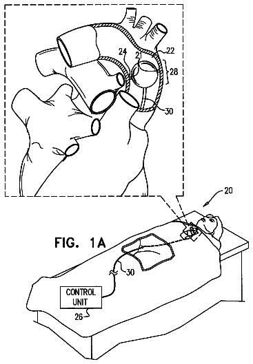
FIGS. 1A-B are schematic illustrations of electrode implantation sites, in accordance with some applications of the present invention;
FIG. 2 is a schematic illustration of an experimental setup of an experiment conducted in accordance with some applications of the present invention;
FIG. 3 is a set of graphs showing the results of stimulating a subject's vagus nerve on several physiological parameters of the subject, as determined in the experiment conducted in accordance with some applications of the present invention;
FIG. 4 is a graph showing a composite result of stimulating the subject's vagus nerve, as determined in the experiment conducted in accordance with some applications of the present invention;
FIG. 5 is a graph showing the dynamic response of a subject to the stimulation of the subject's vagus nerve, as determined in the experiment conducted in accordance with some applications of the present invention;
FIG. 6 is a graph showing the effect of stimulating an aortic site of a pig on blood pressure variability of the pig, in accordance with some applications of the present invention;
FIG. 7 is a graph showing the effect of stimulating an aortic site of a pig on heart rate variability of the pig, in accordance with some applications of the present invention;
FIGS. 8 and 9 are schematic illustrations of electrode configurations that are used, in accordance with some applications of the present invention;
FIG. 10 is a schematic illustration of an electrode implanted in a non-cardiac site in a vicinity of a subject's aorta, in accordance with some applications of the present invention;
FIGS. 11A-C are schematic illustrations of peristaltic dilation of the aorta, in accordance with some applications of the present invention;
FIG. 12 is a schematic illustration of a control unit configured to generate an output in response to a detected aortic electrical parameter, in accordance with some applications of the present invention;
FIGS. 13A-B are schematic illustrations of electrodes disposed on a self-expansible stent, in accordance with some applications of the present invention;
FIGS. 14A-B are schematic illustrations of respective views of a configuration of the self-expansible stent, in accordance with another application of the present invention;
FIGS. 15A-B are schematic illustrations of respective views of an alternative configuration of the self-expansible stent, in accordance with some applications of the present invention;
FIGS. 16A-B are schematic illustrations of respective views of a further alternative configuration of the self-expansible stent, in accordance with some applications of the present invention;
FIG. 17 is a plot of an aortic voltage signal recorded in an aorta of a pig, in an experiment conducted in accordance with some applications of the present invention;
FIG. 18 is a plot showing frequency components of the aortic voltage signal of FIG. 17, as extracted from the raw aortic voltage signal in accordance with some applications of the present invention;
FIG. 19 is a plot comparing a frequency component of the aortic voltage signal of FIG. 17 to the pig's ECG and blood pressure signals, in accordance with some applications of the present invention;
FIG. 20 is a graph showing blood pressure changes measured in five experiments conducted on four pigs, in accordance with some applications of the present invention;
FIG. 21 is a schematic illustration of a transmitter that is placed in a vein that is in the vicinity of an artery in which a stimulating and/or a sensing electrode is placed, in accordance with some applications of the present invention; and
FIG. 22 is a schematic illustration of an electrode configuration for use with the transmitter shown in FIG. 21, in accordance with some applications of the present invention.
Detailed description of embodiments
Reference is now made to FIGS. 1A-B, which are schematic illustrations of a vagal site 22 and an aortic site 24 of a subject, in accordance with some applications of the present invention. For some applications, at least one vagal electrode 20 and at least one aortic electrode 21 are implanted, respectively, at vagal site 22 and aortic site 24. In FIG. 1A, vagus nerve 28 is shown separated from aorta 30 for illustrative purposes, although typically the vagus nerve is disposed adjacently to the aorta at aortic site 24, as shown in FIG. 1B.
For some applications of the invention, a subject suffering from congestive heart failure, diastolic heart failure, and/or hypertension is identified. The subject is treated by implanting an electrode on the subject's vagus nerve at vagal site 22 that is between (a) vagal bifurcation 26 with thoracic cardiac branch, and (b) the thoracic vagal branching into the esophageal plexus. Alternatively or additionally, one or more aortic electrodes 21 are implanted in the vicinity of (i.e., inside, outside, or within the wall of) the subject's aorta 30, at aortic site 24 that is between the bifurcations of the descending thoracic aorta with the first and fifth intercostal arteries 27 and 29. For some applications, aortic electrode 21 is implanted in the vicinity of a portion of the aorta that is adjacent to vagal site 22. For some applications, vagal electrode 20 is implanted on a portion of the vagus nerve that is adjacent to aortic site 24. The subject is treated by driving a current into one or more of the electrode implantation sites. The effects of driving the current into the implantation site typically include ventricular and aortic pressure reduction, an increase in aortic compliance, a decrease in sympathetic tone, an increase in parasympathetic tone, an increase in ejection fraction, a reduction in heart rate, a reduction in left ventricular wall stress, a reduction in left ventricular myocardial oxygen consumption, and/or a reduction in arrhythmia. For example, in experiments conducted by the inventors of the present application, patients that had ECG signals that included two QRS complexes in each cardiac cycle were identified. The patients' arrhythmia was at least partially treated by stimulating the patients in accordance with the techniques described herein.
For some applications, an electrode is implanted inside a vein in the vicinity of vagal site 22. For example, the electrode may be implanted in the vena cava, the innominate vein, the subclavian vein, and/or the left or right internal jugular vein. A current is driven via the intravenously implanted electrode in order to stimulate the vagal site, in accordance with the techniques described herein. Alternatively or additionally, the electrode is implanted inside an artery of the subject in the vicinity of the vagal site other than (or in addition to) the aorta, such as the pulmonary artery and/or the carotid artery, and a current is driven via the electrode in order to stimulate the vagal site.
Typically, the lowering of the subject's blood pressure is achieved by driving the current into one or both of the implantation sites, without causing a substantial change in the subject's heart rate. For some applications, there is no substantial effect on the heart rate, because the current is driven into a site that is further from the CNS than the thoracic cardiac bifurcation 26, and therefore does not have a substantial effect on nerves that directly innervate the subject's heart 32. (For some applications, stimulating the vagus nerve distally to bifurcation 26 also has a heart rate lowering effect, but it is hypothesized by the inventors that this effect is mediated through central controls rather than direct efferent stimulation of the heart.) Typically, the lowering of the subject's blood pressure is achieved due to physiological responses that are in addition to any effects on the firing rate of the subject's baroreceptors, due to the applied current. Further typically, vagal electrode 20 and/or aortic electrodes 21 stimulate at least non-baroreceptor vagal terminals of vagal nerve 28.
For some applications, aortic electrodes 21 are disposed inside the aorta (i.e., electrodes 21 are intravascular electrodes). Alternatively or additionally, the electrodes are disposed in a wall of the aorta. Further alternatively or additionally, vagal electrode 20 is a cuff-electrode (or a different design) that is placed around, or in contact with, the vagus nerve. For some applications, electrode 20 and/or electrodes 21 are chronically implanted at sites 22 and/or 24.
For some applications, the current is driven into the electrode implantation site in coordination with the subject's cardiac cycle and/or respiratory cycle. For example, the subject's ECG may be detected, and the current may be driven into the electrode implantation site responsively to the detection of the QRS complex. alternatively or additionally, the subject's blood pressure may be measured and the current may be driven responsively thereto. Alternatively, the current is driven independently of the subject's cardiac cycle and/or respiratory cycle.
For some applications, driving current into aortic site 24, via electrodes 21, dilates the aorta by increasing nitric oxide (NO) secretion by the wall of the aorta, and/or by increasing the secretion of another vasodilation mediator from the wall of the aorta. For some applications, driving current into aortic site 24, via electrodes 21, dilates the aorta by stimulating efferent nerve ending. For some applications, driving current into aortic site 24, via electrodes 21, dilates the aorta by direct electrical hyperpolarization of the vascular smooth muscle. For some applications, the current has a frequency of between 5 Hz and 50 Hz. For some applications, the current has an amplitude of between 1 mA and 15 mA, e.g., between 2 mA and 3 mA. For some applications, a current having two pulses to eight pulses, e.g., three pulses to five pulses, per cardiac cycle, is driven into the aorta to dilate the aorta. In accordance with respective applications, the current is delivered continuously or intermittently. The current may thus be applied, for example: (a) as an endless train of pulses, (b) during scheduled non-contiguous daily stimulation periods, or (c) during each of at least 24 consecutive hours.
For some applications, driving current into vagal site 22, via electrode 20 stimulates parasympathetic nerve endings and elicits a parasympathetic response. For some applications, driving the current into the vagal site stimulates sympathetic nerve endings, and inhibits sympathetic signaling. For some applications, driving current into aortic site 24, via electrodes 21, has a similar effect on the vagus nerve (i.e., a vagal response), due to the proximity of aortic site 24 to vagal site 22, and/or due to vagal nerve endings that are located at the aortic site. For some applications, driving current into the aortic site generates an aortic response, as described hereinabove, in addition to generating the aforementioned vagal response.
For some applications, vagal site 22 is mechanically stimulated, for example, by mechanically stimulating the vagus nerve at the vagal site, and/or by mechanically stimulating aortic site 24, such that the vagal site also becomes stimulated. For some applications, the vagal site is stimulated using piezoelectric actuator terminals, an electrical motor, and/or an electroactive polymer actuator. For some applications, a balloon is placed in the vicinity of the vagal site, and is actuated to mechanically stimulate the vagus nerve using an external pump.
Reference is now made to FIG. 2, which is a schematic illustration of an experimental setup of an experiment conducted in accordance with some applications of the present invention. Cuff electrodes were placed around a pig's vagus nerve at the following four locations:
cervical location 40;
proximal thoracic location 42 which is proximal to (i.e., closer to the CNS than) where the vagus has crossed the aorta;
medial thoracic location 44, 1-2 cm below the aortic arch as the vagus nerve runs alongside the descending aorta, and just distal to (i.e., further from the CNS than) the thoracic cardiac branch bifurcation with the vagus nerve; and
distal thoracic location 46, just distal to (i.e., in a downstream direction along the aorta from) the crossing of the azygos vein with the aorta, and approximately 3 cm distal to (i.e., further from the CNS than) the thoracic cardiac branch bifurcation with the vagus nerve.
Reference electrodes e1 and e2 were placed inside the pig's body, as shown in FIG. 2. Three Millar pressure transducers M1, M2, and M3 were placed, respectively, in the left ventricle, the proximal descending aorta and in the abdominal aorta proximal to the iliac bifurcation. A Transonic flow transducer 41 was positioned around the aortic root. Three minutes of continuous electrical stimulation was applied to each of the sites. Respective sites of the pig's vagus were stimulated in accordance with the parameters provided in Table 1.
TABLE-US-00001 TABLE 1 Stimulation parameters Active Ref. amplitude freq pulse stimulation pole pole [mA] [Hz] width duration 46 Distal e1 5 50 1-1 ms * 3 min 44 Medial e1 5 50 1-1 ms 3 min 42 e1 5 50 1-1 ms 3 min Proximal 40 e2 5 50 1-1 ms 3 min Cervical * i.e., a 1 ms positive pulse, followed by a 1 ms symmetric negative pulse
Reference is now made to FIG. 3, which is a set of graphs showing the results of stimulating the pig's vagus on several physiological parameters of pig, as determined in the experiment described with reference to FIG. 2. The following parameters were determined. LVPsys--Average systolic left ventricular pressure during the ejection phase (aortic valve opening to aortic valve closure). LVEDP--Left ventricular end diastolic pressure. HR--Heart rate. SV--Stroke volume as measured in the aortic root. LVEW--Left ventricular external work. The integral of the product of left ventricular pressure and aortic flow during ejection phase. PWTT--Pulse wave travel time between two measuring points along the aorta. PWTT is correlated to the square root of the diameter of the aorta divided by stiffness. Hence, increased PWTT (decreased pulse wave velocity) is associated with decreased aortic wall tonus.
The numeric values shown in the graphs of FIG. 3 represent the average of each parameter, for respective stimulation sites, during the entire stimulation regime. The following observations can be made regarding the graphs shown in FIG. 3: Electrical stimulation at all locations induced a reduction of average systolic left ventricular pressure during the ejection phase and heart rate. The systolic left ventricular pressure reduction was maximal in the proximal site and minimal in the cervical site. The left ventricular end diastolic pressure was reduced in the thoracic sites and increased in the cervical site. Heart rate reduction was maximal in the proximal thoracic and cervical sites. Stroke volume did not exhibit a clear trend, as the medial thoracic site yielded a slight decrease and the other sites resulted in 2-4% increase. Left ventricular external work, which is related to cardiac consumption, was lower as a result of stimulation of the thoracic sites and higher while stimulating the cervical site. Stimulation at all of the sites resulted in an increase in pulse wave travel time (i.e., a decrease in aortic tonus). Stimulation of the proximal and medial sites resulted in the largest pulse delay along the aorta.
Reference is now made to FIG. 4, which is a graph showing a composite result of stimulating the pig's vagus, as determined in this experiment. In order to evaluate each of the stimulation sites with one parameter, a first order scoring function was applied. The percentage change in each of the parameters shown in the graph of FIG. 3 was added to the total score, and its sign was determined according to the presumed beneficial direction. Left ventricular external work and left ventricular end diastolic pressure, which are targeted to be reduced (when treating patients suffering from hypertension, for example), were added with negative signs. Pulse wave travel time and stroke volume were added with positive signs. The heart rate reduction was also assigned a positive score.
The function results are plotted in the graph shown in FIG. 4. It may be observed that the thoracic medial site has the highest score, and all of the thoracic sites achieved positive scores. The cervical vagal site achieved an overall negative score, since, although it had a positive effect on heart rate (i.e., heart rate reduction), its effect on pressure and work reduction was non-beneficial across the entire stimulation regime.
Reference is now made to FIG. 5, which is a graph showing the dynamic response of the pig to the stimulation of the pig's vagus nerve, as determined in this experiment. The dynamic response to stimulation of the proximal thoracic and the cervical sites is shown in FIG. 5. The beginnings and ends of the stimulation period are marked with dashed vertical lines, at approximately 60 sec and 180 sec on the proximal thoracic vagus graph, and 60 sec and 230 sec on the cervical vagus graph. Heart rate response in both cases was immediate and continued for the duration of the stimulation period. Similarly, there was stroke volume elevation for the duration of the stimulation, due to stimulation at both sites. The pressure and left ventricular external work responses were not similar, however. The proximal thoracic site generated almost immediate pressure and work reduction. In the cervical site, the pressure reduction appeared only late in stimulation (possibly, as a secondary indirect phenomenon), and the left ventricular external work parameter responded with initial increases that were present across most of the stimulation regime.
In view of the results presented herein, it is hypothesized by the inventors of the present application that, as compared to stimulation of the cervical vagus, stimulation of thoracic vagal sites, as described herein, results in (a) a greater overall desired response with respect to ventricular and aortic blood pressure reduction and decreased aortic tonus, and (b) a more rapid response time to the stimulation. The inventors further hypothesize that placing electrodes on an aortic site that is between the first and the fifth intercostal arteries of a human subject, will generate a similar response to the response of the pig to the placement of electrodes at the proximal, medial and distal sites, in the experiment described herein. The inventors additionally hypothesize that placing electrodes on a vagal site that is adjacent to the aforementioned aortic site will also generate a similar response.
The description continues in the full USPTO document.
 Lapsed, fee not paid14 drawings

