Background of the invention
1. Field of the invention
The present invention relates to an electronic endoscope system having a special imaging function such as autofluorescence imaging (AFI) and narrow band imaging (NBI).
2. Description Related to the Prior Art
In a medical field, diagnosis and treatment using an electronic endoscope system are widely carried out in recent years. In the electronic endoscope system, while white light (normal light), which ranges from a blue wavelength band to a red wavelength band, is applied to the inside of a patient's body cavity, an image sensor such as a CCD captures an image of the light reflected from an internal body part. The captured image is displayed on a monitor. The electronic endoscope system can image the inside of the human body cavity in real time, and facilitates the accurate diagnosis and the effective treatment.
The image (normal image) captured under the normal light shows an overview of the internal body part, but cannot clearly show a capillary blood vessel, an underlying blood vessel, a pit pattern, and irregularities in surface tissue such as a depression or a lump. Since a pathologic lesion is sometimes hidden in such a portion or tissue, it is desired that the capillary blood vessel or the irregularities can be clearly seen in an endoscopic image.
As a method for imaging a tumor lesion including a cancer, for example, autofluorescence imaging (AFI) is known as described in US Application Publication No. 2009/0036743 (corresponding to Japanese Patent Laid-Open Publication No. 2009-34224). In the AFI, special light having a specific wavelength is applied as excitation light to the internal body part, and the image sensor captures an image of autofluorescence that is emitted from an endogenous fluorescent substance of living body tissue in response to the excitation light. According to the AFI, the intensity of the autofluorescence emitted from tumor tissue is weaker than that from normal tissue. Through the use of this property, the tumor lesion is colored differently from a normal portion in a special image. Thus, the tumor lesion is clearly distinguished in the special image, though it is hard to see in the normal image.
Narrow band imaging (NBI) is also known as a method for clearly imaging a superficial blood vessel, which is positioned in the shallow depth of the living body tissue, by application of special light having wavelengths in a specific narrow band, as described in Japanese Patent Laid-Open Publication No. 2001-170009. In the NBI, the superficial blood vessel is distinguished by taking advantage of a light absorbing property of the blood vessel that occurs upon application of the special light and a light scattering property of the living body tissue around the blood vessel. The special image facilitates finding out a lesion that is hard to find out in the normal image.
In a special imaging function such as the AFI and NBI, there is a need to obtain an optimal endoscopic image in accordance with various purposes of the image diagnosis. For example, in the case of trying to find out the lesion in the bright endoscopic image on a whole, the image requires enough intensity even in a far view in which a distal end portion of an electronic endoscope is away from the body part to be imaged. In the case of trying to find out the lesion from a minute portion of the image such as a clot in the blood vessel, the image requires resolution high enough to clearly discern the minute portion even in the far view. However, neither the US Patent Application Publication No. 2009/0036743 nor the Japanese Patent Laid-Open Publication No. 2001-170009 discloses or even suggests an electronic endoscope system that can obtain an optimal endoscopic image in accordance with various purposes.
Summary of the invention
An object of the present invention is to provide an electronic endoscope system that can obtain an optimal image in accordance with various purposes during performing a special imaging function including autofluorescence imaging (AFI) or narrow band imaging (NBI).
An electronic endoscope system according to the present invention includes a light source device, an electronic endoscope, an object distance detector, a binning processing section, and a binning processing control section. The light source device applies to an internal body part illumination light including special light in a specific wavelength band. The electronic endoscope captures an endoscopic image of the internal body part irradiated with the illumination light by using an image sensor. The endoscopic image includes a special image captured under the special light. The object distance detector detects from the endoscopic image an object distance being a distance between the image sensor and an inspection area of the internal body part. The binning processing section applies a binning process to the special image. The binning processing control section determines a binning number used in the binning process in accordance with the object distance.
The special light may be excitation light for exciting autofluorescence from living body tissue of the internal body part. The special image may be an autofluorescence image that captures autofluorescence emitted from the internal body part irradiated with the excitation light.
The binning processing control section preferably increases the binning number with increase in the object distance, and decreases the binning number with decrease in the object distance, in order to adjust intensity of the autofluorescence image. Furthermore, the binning processing control section preferably decreases the binning number with increase in the object distance, and increases the binning number with decrease in the object distance, in order to adjust resolution of the autofluorescence image.
The special light may be NBI light for distinguishing a specific portion including a superficial blood vessel, and the special image may be an NBI image of the internal body part irradiated with the NBI light. In another case, the special light may be narrow band light used for obtaining blood vessel information including a depth of a blood vessel and blood oxygen saturation. The narrow band light includes two types of light having first and second wavelengths. Absorbance of reduced hemoglobin differs from that of oxygenated hemoglobin at each of the first and second wavelengths, and an amount of difference in the absorbance between the reduced hemoglobin and the oxygenated hemoglobin at the first wavelength differs from that at the second wavelength. The special image may be a blood vessel information image of the internal body part irradiated with the narrow band light.
The binning processing control section may increase the binning number with increase in the object distance between a near view having a short object distance and a far view having a long object distance. Also, the binning processing control section may set the binning number larger in a tight close-up state than that in a close-up state. The image sensor is extremely near the inspection area of the internal body part in the tight close-up state, and the image sensor is slightly away from the inspection area in the close-up state as compared to the tight close-up state.
The electronic endoscope system may further include an imaging mode switching section for switching the electronic endoscope system to a special imaging mode. The special imaging mode includes an AFI mode for capturing an autofluorescence image that captures autofluorescence emitted from living body tissue in response to the excitation light applied from the light source device to the internal body part, an NBI mode for capturing an NBI image in which a specific portion including a superficial blood vessel is distinguished by applying the NBI light from the light source device to the internal body part, and a blood vessel information obtaining mode for capturing an image of blood vessel information including a depth of a blood vessel and blood oxygen saturation by applying the narrow band light from the light source device to the internal body part. The binning processing control section preferably determines the binning number in accordance with a type of the special imaging mode and the object distance.
The binning processing section may perform a software binning process in which the special image is constituted of plural pixel groups each of which includes plural adjoining pixels, and intensity of each pixel group corresponds with a sum of intensity of the pixels contained in the pixel group. In another case, the binning processing section may perform a hardware binning process in which the image sensor is constituted of plural pixel groups each which includes plural adjoining pixels, and the image sensor is controlled so as to output a single imaging signal on a pixel group basis. In either case, the binning number is a number of the pixels contained in each pixel group.
The illumination light may include normal light being white light ranging from a blue wavelength band to a red wavelength band. The endoscopic image may include a normal image of the internal body part irradiated with the normal light. The object distance detector may obtain the object distance from the normal image. Furthermore, the object distance detector may detect an exposure amount from the normal image, and calculates the object distance in accordance with the detected exposure amount.
The electronic endoscope system may further include a motion detector for detecting motion of the inspection area of the internal body part from a plurality of the endoscopic images, a frame addition section for applying a frame addition process to a plurality of the special images to produce a single high-quality special image, and a frame addition control section for determining a number of frames to be added in the frame addition process in accordance with the motion of the inspection area detected by the motion detector.
According to the present invention, when the binning process is applied to the special image such as the autofluorescence image, the binning number is determined in accordance with the object distance, which has an influence on the intensity and resolution of the special image. Therefore, it is possible to produce an optimal image that is adequate for its purpose.
Brief description of the drawings
For more complete understanding of the present invention, and the advantage thereof, reference is now made to the following descriptions taken in conjunction with the accompanying drawings, in which:
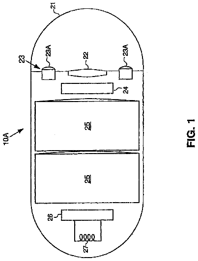
FIG. 1 is a schematic view of an electronic endoscope system according to a first embodiment;
FIG. 2 is a block diagram of the electronic endoscope system according to the first embodiment;
FIG. 3 is a graph showing spectrums of excitation light, autofluorescence, and white light, and a light transmission characteristic of an excitation light cut filter;
FIG. 4 is a perspective view of a distal end portion of an electronic endoscope according to the first embodiment to which an over-tube and a hood are attached;
FIG. 5 is an explanatory view of irradiation areas of the white light;
FIG. 6A is an explanatory view showing a state of a rotary shutter in a first period;
FIG. 6B is an explanatory view showing a state of the rotary shutter in a second period;
FIG. 7 is an explanatory view of a method for controlling the emission amount of the excitation light in accordance with the emission amount of the white light;
FIG. 8 is an explanatory view of irradiation areas of the excitation light;
FIG. 9 is across sectional view of a first light projection unit for projecting the excitation light;
FIG. 10A is an explanatory view of CCD imaging control in a normal imaging mode;
FIG. 10B is an explanatory view of CCD imaging control in a special imaging mode;
FIG. 11 is an explanatory view of a processing flow of a signal processor;
FIG. 12 is a block diagram of a sensitization section;
FIG. 13 is a graph showing the relation between a binning number and an object distance in an intensity adjustment process;
FIG. 14 is a graph showing the relation between the binning number and the object distance in a resolution adjustment process;
FIG. 15 is an explanatory view of a lookup table (LUT) for storing the object distance and the binning number in relation to each other;
FIG. 16 is a block diagram showing an electronic endoscope system according to a second embodiment;
FIG. 17 is a graph showing the relation between the binning number and the object distance in a binning process according to the second embodiment;
FIG. 18 is a block diagram showing an electronic endoscope system according to a third embodiment;
FIG. 19 is a graph showing the light absorbing property of oxygenated hemoglobin and reduced hemoglobin;
FIG. 20 is a graph showing a two-dimensional map of intensity and blood vessel information;
FIG. 21 is a block diagram of an electronic endoscope system according to a fourth embodiment;
FIG. 22 is a plan view of a rotary filter according to a modification example of the first embodiment;
FIG. 23 is a block diagram of an electronic endoscope system according to another modification example of the first embodiment;
FIG. 24 is a cross sectional view of a normal light projection unit of FIG. 23; and
FIG. 25 is a perspective view of a special light probe, a hood, and a distal end portion of an insert section according to further another modification example of the first embodiment.
Description of the preferred embodiments
First Embodiment
An electronic endoscope system 10 of a first embodiment, as shown in FIG. 1, has an autofluorescence imaging (AFI) function for imaging autofluorescence emitted from living body tissue inside a patient's body cavity. The electronic endoscope system 10 is provided with an electronic endoscope 11, an over-tube 13, a hood 14, a processor device 15, a normal light source device 16, a special light source device 17, and a monitor 18. The electronic endoscope 11 captures an image inside the patient's body cavity with an image sensor such as a CCD. Into the over-tube 13, an insert section 20 of the electronic endoscope 11 is inserted. The hood 14 is attached to a distal end portion 24a of the insert section 20. The processor device 15 produces an endoscopic image of the internal body part based on a signal obtained by the CCD. The normal light source device 16 supplies white light (normal light) to irradiate the internal body part therewith. The special light source device 17 supplies excitation light (special light) that excites the autofluorescence from the living body tissue. The monitor 18 displays the endoscopic image.
The electronic endoscope 11 includes the flexible insert section 20 to be introduced into the patient's body cavity, an operation section 21 provided on a proximal end of the insert section 20, and a universal cord 23 for connecting the operation section 21 to both the processor device 15 and the normal light source device 16. At a distal end of the insert section 20, there is formed a bending portion 24, which is composed of a plurality of joint pieces coupled to one another. The bending portion 24 flexibly bends up or down or from side to side in response to operation of an angle knob 26 provided on the operation section 21.
The distal end portion 24a is provided at an end of the bending portion 24. The distal end portion 24a contains an optical system for endoscopy and the like. The distal end portion 24a is aimed at a desired direction inside the body cavity by flexibly bending the bending portion 24. As shown in FIG. 4, the distal end portion 24a is provided with first and second lighting windows 57 and 59 for projecting the white light or the excitation light, an imaging window 62 for receiving the reflected white light or the autofluorescence from the internal body part, an airing/watering nozzle 63 for spraying water or ejecting air to the imaging window 62, and a medical instrument outlet 64 from which a medical instrument led through a channel of the insert section 20 protrudes.
An imaging mode switching button 28 is provided on the operation section 21 to switch the electronic endoscope system 10 between a normal imaging mode for imaging the internal body part with the white light and a special imaging mode for imaging the autofluorescence emitted from the living body tissue upon application of the excitation light. Mode switching information is sent to a system controller 113 (see FIG. 2) of the processor device 15.
In the normal imaging mode, a normal image that is an image of the white light reflected from the internal body part is displayed on the monitor 18. In the special imaging mode, on the other hand, a special image that is an image of the autofluorescence or a composite image of the normal image and the special image is displayed on the monitor 18.
A connector 30 is attached at one end of the universal cord 23 on the side of the processor device 15 and the normal light source device 16. The connector 30 is a complex connector that has a communication connector to be coupled to the processor device 15 and a lighting connector to be coupled to the normal light source device 16. The electronic endoscope 11 is detachably connected to the processor device 15 and the normal light source device 16 via the connector 30.
As shown in FIGS. 1, 2, and 4, the hood 14 attached to the distal end portion 24a of the electronic endoscope 11 is provided with an excitation light cut filter 32. The excitation light cut filter 32 covers the imaging window 62 provided in the distal end portion 24a, in order to cut off part or all of light in a wavelength band of the excitation light out of light entering into the imaging window 62. The excitation light cut filter 32 cuts off the excitation light with high energy in front of the imaging window 62, and prevents the excitation light from entering into a CCD 100 disposed in the depth of the imaging window 62. This is effective at preventing the occurrence of halation by which electric charges become saturated at pixels of the CCD 100 and an image is bleached out.
The over-tube 13 includes a tube body 35, an insertion channel 37 provided inside the tube body 35, and first and second optical fibers 38 and 39. The insert section 20 of the electronic endoscope 11 is inserted into the insertion channel 37. The first and second optical fibers 38 and 39 are disposed on the periphery of the insertion channel 37 to lead the excitation light from the special light source device 17 therethrough.
The insertion channel 37 has a proximal opening 37a being an entrance of the insert section 20 of the electronic endoscope 11, and a distal opening 37b being an outlet of the insert section 20. When the insert section 20 is introduced into the insertion channel 37, the distal end portion 24a of the electronic endoscope 11 with the hood 14 attached protrudes from the distal opening 37b. The insert section 20 of the electronic endoscope 11 is introduced into the patient's body cavity in a state of being inserted in the over-tube 13. On the periphery of the hood 14, first and second light projection units 41 and 42 are adhered to project the excitation light from the first and second optical fibers 38 and 39 to the internal body part, respectively. Note that, the first optical fiber 38 and the first light projection unit 41 are optically coupled by a connector or the like. The second optical fiber 39 and the second light projection unit 42 are optically coupled by a connector or the like.
As shown in FIG. 2, the normal light source device 16 is constituted of a white light source 45, an aperture controller 46, a white light controller 47, a rotary shutter 48, a position detector 49, and a rotation controller 50. While the normal light source device 16 is turned on, the white light source 45 is invariably turned on and emits the white light. The white light is broad band light ranging from the blue wavelength band to the red wavelength band, and, for example, is in a wavelength band of 400 nm to 700 nm as shown in FIG. 3. As the white light source 45, a xenon lamp, a halogen lamp, an LED (light-emitting diode), a fluorescent lamp, or an LD (laser diode) is available by way of example. The white light emitted from the white light source 45 is condensed by a lens 53. After that, the condensed white light is incident upon first and second light guides 55 and 56 through the aperture controller 46.
The first and second light guides 55 and 56 are composed of optical fibers with a large diameter, or the like. A light incident end of each of the first and second light guides 55 and 56 is connected to the normal light source device 16. As shown in FIG. 4, a light exit end of the first light guide 55 is faced to the first lighting window 57 of the distal end portion 24a of the electronic endoscope 11. Alight exit end of the second light guide 56 is faced to the second lighting window 59 of the distal end portion 24a. The white light is applied to the internal body part through the first or second lighting window 57 or 59.
The first and second lighting windows 57 and 59 are symmetric with respect to the excitation light cut filter 32 (or the imaging window 62) provided in the hood 14. As shown in FIG. 5, an irradiation area WL1 of the white light projected from the first lighting window 57 and an irradiation area WL2 of the white light projected from the second lighting window 59 overlap each other at a white light overlapping area WLR. The distal end portion 24a is aimed at a target area T such that the target area T is within the white light overlapping area WLR. Thus, the target area T is irradiated with the white light enough and uniformly.
The hood 14 covers only the imaging window 62 of the distal end portion 24a, and exposes the remaining portion of the distal end portion 24a to the outside in the body cavity. Thus, the hood 14 does not hinder the application of the white light from the first and second lighting windows 57 and 59. The air or water is sprayed from the airing/watering nozzle 63 to the excitation light cut filter 32 of the hood 14. The medical instrument protrudes from the medical instrument outlet 64 inside the body cavity.
As shown in FIG. 2, the aperture controller 46 disposed between the lens 53 and the rotary shutter 48 adjusts the amount of the white light emitted from the white light source 45. The aperture controller 46 is composed of, for example, plural blades for varying the size of an aperture, a motor for moving the blades, and the like. A set value of the aperture controller 46, that is, the amount of the white light to be passed through the aperture is controlled by the white light controller 47 via a driver 47a. The white light controller 47 controls the set value (the white light amount) based on the endoscopic image, which is obtained after signal processing by the processor device 15.
Referring to FIGS. 6A and 6B, the disc-shaped rotary shutter 48 has a sectorial cutout. The cutout of the rotary shutter 48 composes a light transmitting portion 48a for transmitting the white light. The remaining portion of the rotary shutter 48 composes a light shielding portion 48b for cutting out the white light. The rotary shutter 48 is coupled to a rotation axis 70a of the motor 70 disposed in parallel with an optical axis of the white light source 45. Since the rotary shutter 48 rotates by a drive of the motor 70, the light transmitting portion 48a and the light shielding portion 48b are alternately situated in an optical path P of the white light.
The position detector 49, composed of a photosensor or the like, detects which of the light transmitting portion 48a and the light shielding portion 48b is situated in the optical path P. Note that, in the FIGS. 2, 6A, and 6B, the position detector 49 is disposed in the vicinity of the rotary shutter 48 in such a position as to face a side edge of the rotary shutter 48, but may be disposed in another position. For example, the position detector 49 may be disposed so as to face a surface of the rotary shutter 48.
As shown in FIG. 6A, when the light transmitting portion 48a is situated in the optical path P, the white light is incident upon the first and second light guides 55 and 56. Thus, the internal body part is irradiated with the white light. This period is referred to as a first period. On the other hand, as shown in FIG. 6B, when the light shielding portion 48b is situated in the optical path P, the white light is not incident upon the first and second light guides 55 and 56. Thus, the internal body part is shielded from the white light. This period is referred to as a second period. The position detector 49 appropriately sends information about the first and second periods to an excitation light controller 75 of the special light source device 17 and the system controller 113 of the processor device 15.
The durations of the first and second periods depend on the selected imaging mode. The durations of the first and second periods in the special imaging mode are twice as long as those in the normal imaging mode. In other words, the rotation controller 50 shown in FIG. 2 controls the rotary shutter 48 in the special imaging mode at a rotation speed half of that in the normal imaging mode. The rotation controller 50 controls the rotation speed of the rotary shutter 48 via a driver 50a connected to the motor 70.
As shown in FIG. 2, the special light source device 17 includes first and second excitation light sources 72 and 73 and an excitation light controller 75. Each of the first and second excitation light sources 72 and 73 is composed of a light emitting diode or the like, and emits the excitation light having wavelengths of 405.+-.10 nm, as shown in FIG. 3. By irradiating the internal body part with the excitation light in such a wavelength band, the autofluorescence having wavelengths of 420 nm to 650 nm is emitted from an endogenous fluorescent substance in the living body tissue.
In the special imaging mode, the excitation light is invariably emitted from the first and second excitation light sources 72 and 73. Thus, the living body tissue invariably emits the autofluorescence. As shown in FIG. 3, according to a light transmission characteristic of the excitation light cut filter 32, transmittance of short wavelength light having a wavelength of 415 nm or less is approximately zero. Accordingly, the excitation light reflected back to the distal end portion 24a of the electronic endoscope 11 is cut by the excitation light cut filter 32. The amount of the autofluorescence is much smaller than that of the white light. For these reasons, the excitation light and the autofluorescence hardly exerts an influence upon the normal image, even if the normal image is obtained in the presence of the excitation light and the autofluorescence in addition to the white light inside the patient's body cavity.
The excitation light controller 75 controls the light emission amount of the first and second excitation light sources 72 and 73 via drivers 75a and 75b, respectively. The excitation light controller 75 is connected to the white light controller 74, and controls the emission amount of the excitation light in accordance with the control of the emission amount of the white light by the white light controller 47. The emission amount of the excitation light is in correlation with the emission amount of the white light. The emission amount of the excitation light is changed such that the ratio between the emission amount of the excitation light and the emission amount of the white light is kept at 1/10, for example.
As described above, when the emission amount of the white light is changed, the emission amount of the excitation light is automatically and correspondingly changed. Thus, the exposure balance between the normal image and the special image is always maintained in an appropriate state. Note that, the emission amount of the excitation light may be controlled at switching timing from the first period to the second period so as to have a predetermined correlation between the white light and the excitation light, as shown in FIG. 7, instead of being controlled in conjunction with the control of the emission amount of the white light.
The excitation light from the first excitation light source 72 is incident upon the first optical fiber 38 of the over-tube 13. The excitation light from the second excitation light source 73 is incident upon the second optical fiber 39 of the over-tube 13. Then, referring to FIG. 4, the excitation light transmitted through the first optical fiber 38 is ejected from the first light projection unit 41 of the hood 14. The excitation light transmitted through the second optical fiber 39 is ejected from the second light projection unit 42 of the hood 14.
As with the first and second lighting windows 57 and 59 provided in the distal end portion 24a, the first and second light projection units 41 and 42 are symmetric with respect to the excitation light cut filter 32 (or the imaging window 62) of the hood 14. As shown in FIG. 8, an irradiation area EL1 of the excitation light emitted from the first light projection unit 41 and an irradiation area EL2 of the excitation light emitted from the second light projection unit 42 overlap each other at an excitation light overlapping area ELR. Furthermore, the excitation light overlapping area ELR is contained in the white light overlapping area WLR at which the two white light irradiation areas WL1 and WL2 overlap.
Since the distal end portion 24a is aimed at the target area T such that the target area T is enclosed within the excitation light overlapping area ELR of the excitation light irradiation areas EL1 and EL2, the target area T is irradiated enough and uniformly with the excitation light. Therefore, if the entire target area T is formed of normal tissue, the autofluorescence is emitted at substantially the same intensity from the entire target area T. Furthermore, since the excitation light overlapping area ELR is contained in the white light overlapping area WLR, the ratio between the white light amount and the excitation light amount is kept at constant throughout the target area T.
Referring to FIG. 9, the first light projection unit 41 includes a light diffusing member 90, a tubular sleeve member 91 for covering the periphery of the light diffusing member 90, a protective glass plate 92 for sealing one end of the sleeve member 91, and a ferrule 93 fitted into the sleeve member 91 to hold the first optical fiber 38. The first optical fiber 38 extends from a rear end of the ferrule 93 in a state of being covered with a jacket. The first optical fiber 38 with the jacket is covered with a flexible sleeve 95, which is inserted in the sleeve member 91. Since the configuration of the second light projection unit 42 is the same as that of the first light projection unit 41, the description thereof is omitted.
The light diffusing member 90 is made of a transparent resin material that diffuses the excitation light from the first optical fiber 38. In addition to the transparent resin material, transparent ceramic, glass, or the like is available. The light diffusing member 90 may have a light diffusing layer, which has minute bumps and dips or is made of a mixture of particles with different refractive indexes (such as filler), in its surface or the middle. In another case, the light diffusing member 90 may be made of a semitransparent material. The light diffusing member 90 uniformalizes the emission amount of the excitation light by the action of polarization and diffusion. Thus, the irradiation area EL1 and emission amount of the excitation light projected from the first light projection unit 41 are adjustable by appropriately changing the material and composition of the light diffusing member 90. In another case, the irradiation area EL1 and emission amount of the excitation light projected from the first light projection unit 41 may be adjusted by appropriately changing a lens or the protective glass plate 92, instead of or in addition to changing the material and composition of the light diffusing member 90.
As shown in FIG. 2, the electronic endoscope 11 is provided with the CCD 100, an analog frontend processor (AFE) 104, and an imaging controller 106. The CCD 100 receives on its imaging surface 100a light that has transmitted through the excitation light cut filter 32, the imaging window 62, and a condenser lens 102. The CCD 100 performs photoelectric conversion of the light received on its imaging surface 100a, and accumulates signal charges. The accumulated signal charges are read out as an imaging signal. The readout imaging signal is sent to the AFE 104.
The CCD 100 is a color CCD having three color pixels of R-, G-, and B-pixels with R, G, and B color filters, respectively, arranged in its imaging surface 100a. Since the white light ranges from the blue wavelength band to the red wavelength band, all of the R-, G-, and B-pixels react to the white light incident upon the imaging surface 100a. Thus, the imaging signal obtained in receiving the white light contains an R imaging signal outputted from the R-pixels, a G imaging signal outputted from the G-pixels, and a B imaging signal outputted from the B-pixels.
On the other hand, the autofluorescence is substantially in a green wavelength band, though it partly ranges to the blue or red wavelength band. For this reason, the G-pixels certainly react to the autofluorescence incident upon the imaging surface 100a. In other words, the imaging signal obtained in receiving the autofluorescence contains at least the G imaging signal.
The AFE 104 includes a correlated double sampling circuit (CDS) and an automatic gain controller (AGC). The CDS applies a correlated double sampling process to the imaging signal from the CCD 100, to remove noise, which is caused by the drive of the CCD 100, from the imaging signal. The AGC amplifies the imaging signal after the noise removal by the CDS.
The imaging controller 106 controls the imaging operation of the CCD 100. Following the control by the imaging controller 106, the imaging signal is outputted from the AFE 104 at a predetermined frame rate. The imaging controller 106 is connected to the system controller 113 of the processor device 15. Thus, the imaging controller 106 appropriately changes its control method in accordance with the imaging mode and the like that the system controller 113 recognizes at the time of imaging.
In the normal imaging mode, as shown in FIG. 10A, a normal image capture step (NI) for performing the photoelectric conversion of the white light and accumulating the signal charges is carried out in the first period. Then, in synchronization with a turn from the first period to the second period, an imaging signal readout pulse is sent from the imaging controller 106 to the CCD 100. Upon receiving the imaging signal readout pulse, the signal charges accumulated in the CCD 100 are outputted to the AFE 104 as a normal imaging signal. Then, taking a turn from the second period to the first period, the normal image capture step (NI) is carried out again. The above sequential operation is repeated as long as the electronic endoscope system 10 is set in the normal imaging mode.
In the special imaging mode, on the other hand, as shown in FIG. 10B, the normal image capture step (NI) for performing the photoelectric conversion of the white light and accumulating the signal charges is carried out in a first half of the first period. Then, the imaging signal readout pulse is sent from the imaging controller 106 to the CCD 100 in the middle of the first period. Upon receiving the imaging signal readout pulse, the signal charges accumulated in the CCD 100 are outputted to the AFE 104 as the normal imaging signal. Since the excitation light is always applied, only the autofluorescence is incident on the CCD 100 soon after the start of the readout of the normal imaging signal. Then, the CCD 100 carries out a special image capture step (SI) for performing the photoelectric conversion of the autofluorescence and accumulating the signal charges. Although the intensity of the autofluorescence is weak, the CCD 100 can certainly receive a sufficient amount of the autofluorescence enough to form a special image, because the duration of the second period in the special imaging mode is twice as long as that in the normal imaging mode.
After a lapse of predetermined time from the turn to the second period, the imaging signal readout pulse is sent from the imaging controller 106 to the CCD 100. In response to it, the signal charges accumulated in the CCD 100 are outputted to the AFE 104 as a special imaging signal. On the turn from the second period to the first period, the normal image capture step (NI) is carried out again. The above sequential operation is repeated as long as the electronic endoscope system 10 is set in the special imaging mode.
The processor device 15, as shown in FIG. 2, is electrically connected to the electronic endoscope 11, the normal light source device 16, the special light source device 17, the monitor 18, a keyboard (not shown), a printer (not shown), and the like to perform centralized control of the electronic endoscope system 10. The processor device 15 includes a signal processor 110, a frame memory 112, and the system controller 113.
The signal processor 110, which includes an A/D converter 115, a tone correction section 116, and an image processing section 117, applies various processes to the imaging signal outputted from the AFE 104 of the electronic endoscope 11 to produce a picture signal to be displayed on the monitor 18. Based on this picture signal, images of various types are displayed on the monitor 18. Note that, each of the tone correction section 116 and the image processing section 117 is composed of, for example, a software program for making a computer carry out appropriate processing, a memory device such as an EPROM (erasable programmable ROM) for storing the software program, and the like. The frame memory 112 stores digital image data after the A/D conversion and the picture signal after being processed by the image processing section 117 temporarily or whenever the data or picture signal is updated.
The A/D converter 115 converts the imaging signal from the AFE 104 to the digital image data. The image data contains a B component produced from the B imaging signal, a G component produced from the G imaging signal, and an R component produced from the R imaging signal. The image data after the A/D conversion includes normal image data obtained in both the normal imaging mode and the special imaging mode, and special image data obtained in the special imaging mode.
The tone correction section 116 and the image processing section 117 carry out their operation in accordance with a flow of FIG. 11. The tone correction section 116 compensates for the B component of the normal and special image data, which is partly or totally cut out by the excitation light cut filter 32. As shown in FIG. 3, since the electronic endoscope 11 captures the image through the excitation light cut filter 32 that partly or totally cuts out a light component in a wavelength band of 415 nm or less, the B component of the normal and special image data, being in a short wavelength band, is cut out. The tone correction section 116 corrects this B component.
The B component of the normal image data is corrected as follows. First, the following correction expressions
and
are calculated in advance. In the expressions
The description continues in the full USPTO document.
 Lapsed, fee not paid32 drawings