Technical field
The present invention generally relates to radio communications technology and operations in a radio communication network, and in particular to scheduling of data communication in such a radio communication network.
Background
In a radio communication network, such as a so-called Long Term Evolution (LTE) network, there are one or more network nodes, so called radio base stations, arranged for controlling and scheduling data traffic to and from user equipment present within a geographical area or areas, denoted cell(s), served by the radio base station.
The radio base station consequently comprises, for each such cell, equipment in the form of one or more receivers and transmitters, or transceivers, employed for effecting the wireless data communication. These receivers and transmitters consume a significant amount of energy even when currently not transmitting or receiving any data. This energy required to keep the equipment on is denoted static energy consumption to distinguish it from the dynamic energy consumption relating to the energy needed for actually transmitting and receiving data over the air interface.
The main focus in terms of reducing energy consumption in the art has been directed towards decreasing the dynamic energy consumption, mainly by improving the efficiency of the power amplifiers in the receivers and transmitters of the radio base station. However, during a large portion of the operation time of the radio base stations, the traffic load and demands of the radio base stations are not that high, implying that the static energy consumption becomes a major part of the total energy consumption of the radio base stations.
WO2009/041871 discloses a technique for energy reduction in an LTE network. This technique involves performing measurements of system load in a cell. Based on these measurements, a decision is made to vary the number of available downlink sub frames, which are used by a radio base station for the transmission of data to user equipment in the cell. This will reduce the dynamic energy consumption as some of the sub frames will be declared idle and the transmitters can consequently be in stand-by mode during these idle sub frames.
Summary
The above identified application WO2009/041871 contributes to saving energy by radio base stations in the radio communication network. There is, however, still a need for further reducing the energy consumption, in particular reducing the static energy consumption of the radio base stations.
It is a general objective to provide a data communication scheduling in a radio base station.
It is a particular objective to provide such a data communication scheduling allowing reduction of static power consumption by the radio base station.
These and other objectives are met by embodiments as defined by the accompanying patent claims.
The present invention relates to a data communication scheduling system adapted for arrangement in a radio base station serving multiple cells in a radio communication network. The data communication scheduling system comprises at least one transmitter and at least one receiver per cell. Each cell further has its dedicated antenna interface connectable to a respective antenna arrangement of the radio base station and used for transmitting data from its connected transmitter/transmitters and forwarding captured data to its connected receiver/receivers.
In order to reduce the power consumption of the radio base station and in particular the static power consumption, only a subset of the transmitters and receivers are active in the data communication scheduling system, while remaining transmitters and receivers are at least temporarily turned off.
A transmitter controller is arranged in the data communication scheduling system in order to effectuate efficient downlink transmission to user equipment present in the served cells using the reduced number of active transmitters. The transmitter controller controls at least one active transmitter to be shared between multiple cells during different sub frames of a radio frame. This means that the at least one transmitter is employed for transmission of data destined for user equipment in a first of the cells during at least one sub frame in the radio frame. The same at least one transmitter is then employed for transmission of data destined for user equipment in a second cell during at least one other sub frame in the radio frame.
Furthermore, the transmitter controller controls the operation of the transmission branch in the data communication scheduling system so that each served cell is assigned at least one sub frame of the radio frame for downlink transmissions for each respective cell.
A receiver antenna system multiplexer selectively interconnects the active receivers and the antenna interfaces to forward received data from an antenna interface to one of the active receivers. The operation of the receiver antenna system multiplexer is controlled by a receiver controller so that at least one of the active receivers is shared between multiple cells. This means that the at least one receiver is employed for reception of data from user equipment in a first of the cells during at least one sub frame in the radio frame. The same at least one receiver is then employed for reception of data from user equipment in a second cell during at least one other sub frame in the radio frame.
Furthermore, the receiver controller controls the receiver antenna system multiplexer to selectively interconnect the receivers and antenna interfaces so that each antenna interface dedicated for a respective cell is connected to an active receiver during at least one sub frame assigned for reception of uplink data in the cell. This at least one sub frame is furthermore scheduled to follow the at least one downlink sub frame assigned to the same cell by a predefined sub frame distance.
A radio base station comprising the data communication scheduling system and multiple antenna arrangements connected to the antenna interfaces of the data communication scheduling system is also disclosed.
A method for scheduling data communication involves scheduling data transmission by a radio base station for the multiple served cells using merely a subset of the transmitters arranged in the radio base station. The scheduling is performed so that at least one active transmitter is shared between multiple cells and consequently is used for transmitting data destined to a first cell during at least one sub frame in a radio frame and transmitting data destined to a second cell during at least one other sub frame in the radio frame.
Active receivers are selectively connected to the antenna arrangements of the radio base station so that at least one active receiver is connected to a first antenna arrangement during at least one sub frame of the radio frame and to a second antenna arrangement during at least one other sub frame of the radio frame. This selective connection is further conducted so that each antenna arrangement of the respective cells is connected to an active receiver during at least one sub frame assigned for reception of data for the respective cell and being present, at a predefined sub frame distance, after the at least one downlink sub frame scheduled for the respective cell.
The embodiments allow a reduction in the static power consumption of the radio base station. Furthermore, also the total power consumption of the radio base station is reduced at low and moderate traffic load situations but with maintained capacity and quality of service.
Brief description of the drawings
The embodiments, together with further objectives and advantages thereof, may best be understood by making reference to the following description taken together with the accompanying drawings, in which:
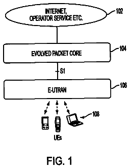
FIG. 1 is a schematic overview of a radio communication system according to an embodiment;
FIG. 2 illustrates a portion of a radio base station according to prior art techniques;
FIG. 3 illustrates a portion of a radio base station according to an embodiment;
FIG. 4 illustrates a portion of a radio base station according to another embodiment;
FIG. 5 illustrates a portion of a radio base station according to a further embodiment;
FIG. 6 illustrates an implementation of the receiver antenna system multiplexer in FIGS. 3 to 5 according to an embodiment;
FIG. 7 illustrates an implementation of the receiver antenna system multiplexer in FIGS. 3 to 5 according to another embodiment;
FIG. 8 illustrates an implementation of the transmitter antenna system multiplexer in FIG. 3 according to an embodiment;
FIG. 9 illustrates an implementation of the transmitter antenna system multiplexer in FIG. 3 according to another embodiment;
FIG. 10 illustrates an implementation of the transmitter antenna system multiplexer in FIG. 3 according to a further embodiment;
FIG. 11 illustrates an implementation of the transmitter antenna system multiplexer in FIG. 3 according to yet another embodiment;
FIG. 12 schematically illustrates omni transmission downlink and time multiplexing uplink according to an embodiment;
FIG. 13 illustrates an embodiment of a radio frame with scheduled transmission and reception with omni transmission downlink and time multiplexing uplink;
FIG. 14 schematically illustrates time multiplexing downlink and uplink according to an embodiment;
FIG. 15 illustrates an embodiment of a radio frame with scheduled transmission and reception with time multiplexing downlink and uplink;
FIG. 16 illustrates another embodiment of a radio frame with scheduled transmission and reception with time multiplexing downlink and uplink;
FIG. 17 illustrates a further embodiment of a radio frame with scheduled transmission and reception with time multiplexing downlink and uplink;
FIG. 18 is a flow diagram illustrating a data communication scheduling method according to an embodiment;
FIG. 19 is a flow diagram illustrating additional, optional steps of the data communication scheduling method according to an embodiment;
FIG. 20 is a flow diagram illustrating additional, optional steps of the data communication scheduling method according to another embodiment;
FIG. 21 is a flow diagram illustrating an additional, optional step of the data communication scheduling method according to an embodiment;
FIG. 22 is a flow diagram illustrating an additional, optional step of the data communication scheduling method according to another embodiment;
FIG. 23 illustrates an embodiment of a radio frame with scheduled transmission and reception for a time division duplex mode; and
FIG. 24 illustrates an embodiment of a radio frame with scheduled downlink transmission using Hybrid Automatic Repeat ReQuest.
Detailed description
Throughout the drawings, the same reference numbers are used for similar or corresponding elements.
Embodiments as disclosed herein relate to data communication scheduling by a radio base station in a radio communication network and in particular using such data communication scheduling to enable a reduction in the static power consumption of the radio base station.
The data communication scheduling and the static power consumption that it enables are implementable in a radio base station serving multiple cells or sectors in the radio communication network. Thus, the radio base station comprises equipment for providing communication services to user equipment present in different geographical areas or cells served by the single radio base station. FIG. 1 is an overview of a part of a radio communication network 1 comprising such a radio base station 100. In the figure, the radio base station 100 has been exemplified as a radio base station serving three cells 10, 20, 30 and any user equipment 210, 220, 230 present in the respective geographical areas of the cells 10, 20, 30. However, a three-sectorized cell arrangement as in FIG. 1 should merely be seen as an illustrative embodiment and the invention is not limited thereto. Furthermore, the geographical areas of the multiple cells 10, 20, 30 served by the radio base station 100 do not necessarily together have to cover the full 360.degree. area around the radio base station 100. In such a case, the combined coverage area of the multiple cells 10, 20, 30 instead merely amounts to a portion of the full 360.degree. area.
The expression "radio base station" as used herein also encompasses the more recent entities, such as NodeB and evolved NodeB (eNodeB), which are capable of handling more than one cell, and other corresponding network nodes, such as base transceiver station (BTS) and base station (BS).
Similarly, "user equipment" will be used to indicate different types of radio terminals, such as a mobile station, mobile user equipment, a laptop, etc. having functionality for wirelessly communicating with radio base stations in the radio communication network.
FIG. 2 is a schematic illustration of a portion of the transmission and reception equipment in a radio base station 100. The radio base station 100 comprises a radio equipment controller (REC) 105 arranged for handling the base band signal processing and the medium access control (MAC) scheduler. The REC 105 is connected to the radio equipment (RE) 101, 102, 103 comprising the actual radio receivers and radio transmitters for the cells. In a typical implementation, as illustrated in FIG. 2, a radio base station 100 has one RE 101, 102, 103 per served cell, although the RE 101, 102, 103 may comprise one or more receivers and transmitters dedicated for reception of data from user equipment and transmission of data to user equipment present in the area of the cell, respectively.
In the following, the expressions "receiver" and "transmitter" are used for denoting the equipment in the RE 101, 102, 103 employed for receiving data by means of a connected antenna arrangement 110, 120, 130 and transmitting data by means of a connected antenna arrangement 110, 120, 130. The receiver and transmitter also comprise functionality known in the art for processing the received and transmitted data, such as power amplifiers, etc. In the art, the expression "transceiver" is sometimes employed for denoting the combined functionality of a receiver and transmitter. The expressions "receiver" and "transmitter" therefore also encompass the receiving branch and the transmitting branch of such a transceiver, respectively.
Embodiments relates to a data communication scheduling system that is adapted for arrangement in a radio base station serving at least M.gtoreq.2 cells. The data communication scheduling system is configured for sharing transmitter/transmitters and receiver/receivers between the cells in order to reduce the static power consumption of the data communication scheduling system and the radio base station, in which it is implemented. However, note that even though the data communication scheduling and static power consumption reduction of the embodiments is applied to M cells of the radio base station, one or more further cells must not necessarily be involved in the data communication scheduling but instead utilize its/their dedicated transmitter/transmitters and receiver/receivers without any sharing to or by other cells served by the radio base station.
The radio base station also comprises at least M antenna arrangements or systems arranged for performing the actual transmission and reception of data. In a particular embodiment, the radio base station comprises one such antenna arrangement per cell but may optionally comprise at least one additional antenna arrangement as is further described herein. An antenna arrangement can comprise a single combined reception and transmission antenna, a dedicated reception antenna and a dedicated transmission antenna or multiple dedicated or combined reception and transmission antenna for the purpose of achieving antenna diversity and transmit diversity and/or reception diversity.
In operation, these M antenna arrangements are connected to the data communication scheduling system through respective antenna interfaces. As a consequence, the data communication scheduling system comprises at least M antenna interfaces, where the actual value of M is dictated by the number of antenna arrangements in the radio base station, in which the data communication scheduling system is arranged or is to be arranged.
According to the embodiments, the data communication scheduling system also comprises M.sub.TX transmitters and M.sub.RX receivers, where M.sub.TX.gtoreq.M and M.sub.RX.gtoreq.M. In a particular embodiment M.sub.TX.gtoreq.M.sub.RX. These transmitters and receivers are distributed among the cells so that each cell of the M cells is assigned at least one transmitter and at least one receiver. For instance, each cell can comprise one or two transmitters and one or two receivers in its RE. Furthermore, each cell has an assigned antenna arrangement connected to its RE with the at least one assigned receiver and transmitter. In a preferred embodiment, the number of transmitters assigned to a cell and present in its RE is equal to the number of receivers assigned to the cell. The embodiments are, though, not limited to that preferred implementation but can have different number of assigned transmitters as compared to assigned receivers for the cells. Note also that even though the M cells all preferably have the same number of assigned transmitters and receivers, the embodiments are not limited thereto.
The M.sub.TX transmitters and M.sub.RX receivers of the data communication scheduling system are connectable to at least one antenna interface of the M antenna interfaces. In operation, the antenna interfaces are connected to respective antenna arrangements in order to direct received data from an antenna arrangement, via an antenna interface, to a correct receiver and forward data from a transmitter to an intended antenna arrangement as will be described further herein.
In the following, the embodiments will be described further in connection with a Long Term Evolution (LTE) radio communication network. In LTE, a time-domain structure is employed for effecting data communication. A radio frame or frame is of length 10 ms and consists of 10 sub frames of length 1 ms each.
According to the embodiments, the radio frame structure of LTE is employed in an inventive way to allow a temporary shutting off of radio equipment, i.e. transmitters and receivers of a data communication scheduling system, and instead sharing radio equipment between cells. Thus, the embodiments allow saving static power consumption of the data communication scheduling system and of a radio base station, in which the data communication scheduling system is arranged, by merely utilizing a subset of the available transmitters and receivers for scheduling the data communication in the served cells. The remaining transmitters and receivers can consequently be turned off to reduce the power consumption. Turning off a transmitter or receiver preferably involves temporarily shutting off the power to all the equipment and functionality housed within the transmitter or receiver. Alternatively, a subset of this equipment and functionality can be powered down, in particular the power-consuming power amplifiers and the optional cooling fans arranged in connection with the power amplifiers. From operation point of view, it is immaterial whether the full transmitter/receiver is turned off or only some of its including equipment/functionality as the transmitter/receiver is anyhow inoperable during the turned off period.
The embodiments are in particular directed towards providing a data communication scheduling in the radio base station that enables turning off transmitters and receivers but still serves the data traffic in the cells. The data communication scheduling can, however, also be used in connection with unintentional stops in the operation of transmitters and receivers due to malfunctions. In both cases the traffic in the different cells are handled by merely a subset of the transmitters and receivers and subject to the particular data communication scheduling.
According to the embodiments, a transmitter controller of the data communication scheduling system is arranged for scheduling transmission by the radio base station for the M cells during a radio frame using merely N.sub.TX transmitters, where 1.gtoreq.N.sub.TX<M.sub.TX. This means that the remaining M.sub.TX-N.sub.TX transmitters of the data communication scheduling system are intentionally turned off to save power or unintentionally shut down due to malfunctions. The scheduling controlled by the transmitter controller is conducted so that at least one transmitter of the N.sub.TX transmitters is arranged for transmission of data destined for user equipment in a first cell of the M cells during at least one sub frame in the radio frame. Correspondingly, the same at least one transmitter is switched for transmission of data destined for any user equipment in a second cell of the M cells during at least one other sub frame in the radio frame. In other words, at least two of the cells associated with the radio base station are served by the same at least one transmitter during a radio frame. The at least one transmitter is therefore switched between transmission of data destined for a first cell and data destined for a second cell during a single radio frame.
Furthermore, the transmitter controller controls the scheduling of data transmission so that each cell of the M cells is assigned at least one sub frame in the radio frame for transmission of data destined for user equipment in the respective cell. The scheduling consequently guarantees that even though only a subset, i.e. N.sub.TX of the transmitters are available, each cell is guaranteed at least one sub frame for communication of data intended for any user equipment present in the geographical area of the particular cell.
This at least one sub frame therefore preferably carries the system information required by user equipment in order to access the LTE network. Such information includes information needed in order to compile and transmit a random access to the radio base station. In LTE, the information includes information of the frequency at which the random access should be transmitted and at least one random access preamble applicable in the cell. The system information is generally carried by the Physical Broadcast Channel (PBCH). Correspondingly, information allowing user equipment to synchronize to the radio frame structure of a cell is traditionally carried by the Primary Synchronization Signal (PSS) and the Secondary Synchronization Signal (SSS). Thus, the PBCH, PSS and SSS comprise the information needed by user equipment in order to compile and transmit a random access to the radio base station to thereby become connected to the radio communication network. These channels are consequently included in the one or more of the respective at least one sub frame guaranteed to be assigned to each cell of the radio base station by the transmitter controller. Any other downlink data intended for one or more user equipment in the cell is also transmitted in the at least one sub frame dedicated to the cell.
The transmitter controller, thus, performs a downlink scheduling using the limited number N.sub.TX of available transmitters for effectuating the necessary control signaling in addition to upholding sufficient downlink traffic transmissions for the user equipment.
The data communication scheduling system also comprises a so-called receiver antenna system multiplexer connected to at least N.sub.RX receivers among the M.sub.RX receivers and the M antenna interfaces assigned to the M cells. More preferably, the receiver antenna system multiplexer is connected to all M.sub.RX receivers in the data communication scheduling system. This receiver antenna system multiplexer is arranged for selectively connecting a receiver of the N.sub.RX receivers to an antenna interface of the M antenna interfaces. In similarity to the transmitters discussed above, only a subset of the M.sub.RX receivers is indeed available for the radio base station during at least a portion of time as 1.gtoreq.N.sub.RX<M.sub.RX. The remaining M.sub.RX-N.sub.RX receivers are fully or at least partly shut down. The receiver antenna system multiplexer is further connected to and controlled by a receiver controller. This receiver controller causes the receiver antenna system multiplexer to selectively interconnect the N.sub.RX available receivers and the M antenna interfaces so that at least one receiver of the N.sub.RX receivers is connected to a first antenna interface assigned to a first cell during at least one sub frame of the radio frame. This at least one receiver is then connected to a second antenna interface assigned to a second, different cell during at least one other sub frame of the radio frame. In other words, at least one of the available N.sub.RX receivers is shared between at least two, possibly all M cells served, in operation, by the radio base station. This means that the receiver controller controls the receiver antenna multiplexer to switch the at least one receiver to receive data during at least a first sub frame from the first antenna interface and then receive data during at least a second sub frame from a different antenna interface.
In addition, the receiver controller controls the receiver antenna system multiplexer to selectively interconnect receivers and antenna interfaces so that each cell has its antenna interface connected to a receiver of the N.sub.RX receivers during at least one sub frame. This at least one sub frame is assigned for reception of uplink data from user equipment in the respective cell. In addition, the sub frame is present at a predefined sub frame distance from the at least one sub frame assigned to the respective cell by the transmitter controller.
This latter requisite is necessary in order to achieve correct data communication in a LTE communication network as a correct downlink transmission in a cell will be responded by a receiving user equipment by an acknowledgement a predefined sub frame distance later on the uplink. In more detail, LTE employs a Hybrid Automatic Repeat ReQuest (HARQ) protocol in the MAC layer. This HARQ protocol is mainly employed to correct block errors that occur over the air interface. HARQ processes are used to associate a potential retransmission to its original transmission in order to enable soft combining at the HARQ receiver. Only when the HARQ receiver has reported correct reception of the data sent on a HARQ process may it be used to transmit new data. Consequently, before the reception of a HARQ status report or acknowledgement from the user equipment, the radio base station cannot know if it should send new data or a retransmission of the "old data".
Therefore, a downlink sub frame in a cell is consequently scheduled to have an associated uplink sub frame allowing reception of any acknowledgements/not acknowledgements (ACK/NACK) from user equipment in the cell. This uplink sub frame is today scheduled four sub frames after the downlink sub frame.
It should, though, be noted that the exact structure of the radio frame and the mapping of control and data channels onto the radio frames and any ACK/NACK scheduling is an ongoing process in 3GPP. Hence, the description provided herein is used merely as an example in order to illustrate possible implementations of the embodiments and it should be understood that variations may occur, with the embodiments being equally applicable to radio communication networks having other radio frame structures, channel mappings and/or ACK/NACK scheduling.
The invention will now be further described with reference to particular embodiments illustrating the implementation of the technical features. FIG. 3 is a schematic illustration of the data communication portion of a radio base station 100 and a data communication scheduling system 300 according to an embodiment. In this illustrative example, the radio base station serves M=3 cells and consequently has three antenna arrangements 110, 120, 130, each dedicated for data transmission and reception in a respective cell. Three REs 101, 102, 103 are connected to the antenna arrangements 110, 120, 130 through a receiver antenna system multiplexer (RX ASM) 140 and a corresponding transmitter antenna system multiplexer (TX ASM) 150 and through respective antenna interfaces 115, 125, 135. The multiplexers 140, 150 are controlled by a receiver controller (RX ctrl) 145 and a transmitter controller (TX ctrl) 155.
In the illustrative example, each RE 101, 102, 103 comprises a receiver (RX) 112, 122, 132 and a transmitter (TX) 111, 121, 131, thus M.sub.RX=M.sub.TX=3.
In a typical implementation, at least one of the receivers 112, 122, 132 and at least one of the transmitters 111, 121, 131 is turned off by a receiver status controller (RX status ctrl) 162 and a transmitter status controller (TX status ctrl) 161, respectively. In a first embodiment, the receiver status controller 162 turns off the power of one of the receivers 132 and the transmitter status controller 161 likewise turns off the power of one of the transmitters 131, preferably arranged in the same RE 103 as the turned off receiver 132. In a second embodiment, two receivers 122, 132 and two transmitters 121, 131 are turned off by the receiver and transmitter status controllers 161, 162.
The operation of the receiver and transmitter status controllers 161, 162 is preferably based at least partly on expected traffic load in the three cells. Thus, if the expected traffic load is at low or moderate levels one or two of the three available receiver-transmitter pairs 121, 131, 122, 132 may indeed be turned off and the remaining receiver-transmitter pair/pairs 111, 112 will be enough to handle the uplink and downlink traffic in the three cells.
Statistical information based on measurements during different portions of a day, week and/or a month can be collected by the network operator and used as a basis for determining intervals of a day, week and/or month, during which the traffic load is expected to be low enough to allow turning off receiver-transmitter pair/pairs. In particular, during night time the expected number of user equipment present in the areas of the three cells and requiring communication resources from the radio base station could on average be low enough that the receiver and transmitter status controllers 161, 162 are pre-configured to turn off the power of the selected at least one transmitter 121, 131 and receiver 122, 132 during the night.
Alternatively, an optional load estimator 180 can be arranged in the data communication scheduling system 300, preferably in the REC 105. This load estimator 180 estimates the amount of currently buffered data to and from the user equipment in the cells to thereby get an estimate of the traffic status in the cells. If the total amount of data traffic is estimated to be below a traffic threshold, the load estimator 180 signals the receiver and transmitter status controllers 161, 162 to turn off the power of a subset of the transmitters 121, 131 and the receivers 122, 132. The load estimator 180 may optionally have access to multiple different traffic thresholds. In such a case, the receiver and transmitter status controller 161, 162 can turn off the power of a first transmitter 131 and receiver 132 if the estimated traffic load is below a first traffic threshold but exceeds a second traffic threshold. First when the estimated traffic load is below the second traffic threshold will the receiver and transmitter status controllers 161, 162 turn off the power of also the second transmitter 121 and receiver 122, 132.
In the embodiment illustrated in FIG. 3, the receiver and transmitter status controllers 161, 162 are both implemented in the REC 105 of the data communication scheduling system 300.
In the following discussion in connection to FIG. 3, it is non-limitedly assumed that the receiver and transmitter status controllers 161, 162 turn off the power of two of the three receivers 112, 122, 132 and transmitters 111, 121, 131, i.e. N.sub.RX=N.sub.TX=1.
As was mentioned in the foregoing, the receiver antenna system multiplexer 140 connects the three receivers 112, 122, 132 with the three antenna interfaces 115, 125, 135 and, when being arranged in the radio base station 100, therefore with the three antenna arrangements 110, 120, 130. Consequently, data captured by the antenna arrangements 110, 120, 130 are forwarded via the antenna interfaces 115, 125, 135 to the correct receiver 112, 122, 132 by the receiver antenna system multiplexer 140. The receiver antenna system multiplexer 140 in particular selectively connects the single active receiver 112 to the different antenna interfaces 115, 125, 135 during different sub frames as controlled by the receiver controller 145.
Correspondingly, the transmitter antenna system multiplexer 150 selectively connects the three transmitters 111, 121, 131 with the three antenna interfaces 115, 125, 135 and, when being arranged in the radio base station 100, therefore with the three antenna arrangements 110, 120, 130. Thus, data from the transmitters 111, 121, 131 is forwarded by the transmitter antenna system multiplexer 150 through the antenna interfaces 115, 125, 135 to the correct antenna arrangement 110, 120, 130. The transmitter antenna system multiplexer 150 in particular selectively connects the single active transmitter 111 to the different antenna interfaces 115, 125, 135 during different sub frames as controlled by the transmitter controller 155.
The transmitter controller 155 consequently controls the transmitter antenna system multiplexer 150 to selectively connect the transmitter 111 to the antenna interfaces 115, 125, 135 so that the respective antenna interface 115, 125, 135 of each of the three cells is connected to the transmitter 111 during at least one sub frame of a radio frame. This means that the transmitter antenna system multiplexer 150 will switch between forwarding data from the transmitter 111 to the first antenna interface 115, the second antenna interface 125 and the third antenna interface 135. Furthermore, during the radio frame the transmitter 111 is dedicated for processing and forwarding data to each of the three antenna interfaces 115, 125, 135 but in different sub frames.
Correspondingly, the receiver controller 145 controls the receiver antenna system multiplexer 140 to selectively connect the receiver 112 to the three antenna interfaces 115, 125, 135 so that the respective antenna interfaces 115, 125, 135 of each of the three cells is connected to the receiver 112 during at least one sub frame of the radio frame. Furthermore, the sub frame during which the receiver 112 is connected to the antenna interface 115 of a given cell is present at the predefined sub frame distance from the sub frame during which the transmitter 114 is connected to the same antenna interface 115.
FIG. 14 schematically illustrates a radio frame for the uplink (UL) and the downlink (DL) and the assignment of sub frames to the three different cells denoted A, B and C in the figure. In the figure, the uplink is indicated as one stream. LTE normally uses receiver diversity in the uplink. However, the figure merely indicates a single stream in order to simplify the understanding of the embodiments. The operations of the receiver and antenna system multiplexers 140, 150 will cause the transmitter 111 and the receiver 112 to be time multiplexed between the three cells.
FIG. 15 is an example of radio frame structure with time multiplexed uplink and down link transmission for one active RE 101 and three served cells. In this embodiment, the transmitter 111 sends to each of the cells A, B, C in a respective sub frame 50, 51, 52 that recurs every 5 ms. As a consequence, each cell is assigned at least two sub frames 50, 51, 52 for downlink transmission during a radio frame 40 and these correspond to sub frames 0 and 5 in each cell. This is preferred distribution of sub frames as today in LTE, PBCH, PSS and SSS appear in sub frames 0 and 5 in each radio frame 40 for a cell. As a consequence, the same distribution of control signals within a radio frame 40 as the LTE standard can thereby be achieved.
Note that the sub frame indicated with reference number 50 in the figure corresponds to sub frame 0 for the first cell A. Correspondingly, the sub frame indicated by 51 is interpreted as sub frame 0 for the second cell B and so on.
The remaining four sub frames 58 in the radio frame 40 can be used arbitrary in the cells and preferably depending on the traffic demand in each cell. However, in order to allow ACK/NACK of downlink traffic, a downlink sub frame 50, 51, 52 assigned for a cell should be accompanied with an uplink sub frame 53, 54, 55 assigned to the same cell four sub frames later.
As is illustrated in the figure, the downlink sub frames 50, 51, 52 assigned to the different cells have corresponding uplink sub frames 53, 54, 55 present four sub frames later. One of these uplink sub frames 53, 54, 55 can be used for random access (RACH, Random Access Channel) reception in the cell.
In order to also decrease the dynamic power consumption of the radio base station 100, as few of the four remaining sub frames 58 are used possible. Thus, in a minimum load scenario, only six of the ten sub frames in a radio frame 40 are used for communicating data. As the traffic load increases in one or more of the cells, these extra sub frames 58 can be used to serve that traffic.
In order to improve the channel estimation for user equipment, extra sub frames can be assigned for the cell in the sub frame before the sub frame 50, 51, 52 carrying the synchronization channels. In such a case, the user equipment has access to two consecutive downlink sub frames to better detect the synchronization channels by averaging the channel estimate. With a single transmitter available and switched between the three different cells, this cannot be accomplished for all the cells. If the radio base stations in the radio communication network are time synchronized to each other, which is common in LTE, the synchronization channels will have a 1/3 reuse, thus reducing the interference and, improving the ability for user equipment to estimate the synchronization channels. As consequence, it is generally not necessary to have two consecutive downlink sub frames per cell.
In an embodiment, the REC 105 will primarily schedule the traffic in each cell on the same sub frame 50, 51, 52 as is transmitting the synchronization channel for that cell. This gives 10% of the maximum capacity in the cell and >20% of the average capacity, or even more if the radio base stations are synchronized with 1/3 reuse. If the traffic load is higher extra sub frames 58 can be assigned to the cells. When the traffic load is higher than can be served by one transmitter 111, the transmitter status controller 161 switches on one of the turned off transmitters 121.
The receiver and antenna system multiplexers 140, 150 should be able to operate on micro second level, thus between sub frames, in order correctly forward data between the active receiver 162 or transmitter 161 and the correct antenna arrangement 110, 120, 130.
FIG. 4 is an illustration of the communicating portion of a radio base station 100 and a data communication scheduling system 300 according to another embodiment. In contrast to the embodiment of FIG. 3, this data communication scheduling system 300 does not comprise any transmitter antenna system multiplexer. Thus, no selective forwarding of data between a single active transmitter and the three antenna interfaces 115, 125, 135 is conducted in this embodiment.
The description continues in the full USPTO document.
 Lapsed, fee not paid10 drawings