Lapsed, fee not paid3 drawings
Vehicles & Drones · US 8,623,559 B2
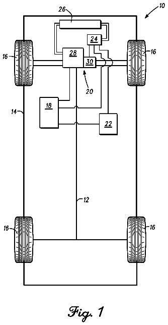
Fuel cell system with suction operation for an aircraft
A fuel cell system for an aircraft is stated, which fuel cell system comprises a fuel cell unit and a suction module.
US 8,624,977 B2 · Assignee: Clarion Co., Ltd. · Inventors: Satoh; Noriyuki
Sheet 1 of 11 from the published document. All sheets in the USPTO PDF
A vehicle-peripheral image displaying system (a side view monitor system A1) comprises a side camera 1, a monitor 3 and an image processing controlling unit 2, wherein the image processing controlling unit 2 includes an image processor 43 configured to perform a viewpoint conversion of the actually shot camera image input from the side camera 1 into a virtual camera image which is to be converted as if it is viewed from the driver's eye position, an image memory 44 configured to store a vehicle interior image which is previously shot from the driver's eye position as a vehicle interior image, and a superimposing circuit 46 configured to make the vehicle interior image translucent to form a translucent vehicle interior image, to perform an image composition such that the translucent vehicle interior image is superimposed on the virtual camera image, and to produce a composite image which represents the virtual camera image transparently through the translucent vehicle interior image.
Today, a practically used side view monitor system, which has a side camera (CCD camera or the like) provided inside a side mirror, displays an actually shot camera image output from the side camera on a monitor screen of a front display unit which is also used for a navigation system. That is, a front lateral part of the vehicle, which is blind from a driver, is displayed on the monitor screen so that the driver can recognize a situation of the blind area. However, since the side camera is provided inside the side mirror, there is a greatly inadequate parallax between a viewing position of the camera and a viewing position of a driver. Shapes of an obstacle or other objects on the camera image and the shapes which can be seen from the driver's seat are totally different. In response, usually by a habituation of the driver, the driver reconfigures the camera image in his head and judges
8 of 11 drawing sheets so far from the published document, cropped to the drawing. Every sheet is in the USPTO PDF.
What the patent claimed, word for word. All of it is now free to use.
The present invention relates to a vehicle-peripheral image displaying system which displays a vehicle-peripheral image including a blind area on a monitor screen of a vehicle interior based on the camera image obtained by a vehicle-mounted external camera.
Today, a practically used side view monitor system, which has a side camera (CCD camera or the like) provided inside a side mirror, displays an actually shot camera image output from the side camera on a monitor screen of a front display unit which is also used for a navigation system.
That is, a front lateral part of the vehicle, which is blind from a driver, is displayed on the monitor screen so that the driver can recognize a situation of the blind area.
However, since the side camera is provided inside the side mirror, there is a greatly inadequate parallax between a viewing position of the camera and a viewing position of a driver. Shapes of an obstacle or other objects on the camera image and the shapes which can be seen from the driver's seat are totally different.
In response, usually by a habituation of the driver, the driver reconfigures the camera image in his head and judges whilst restructuring a positional relationship between the objects so that consistency with the image which the driver is actually viewing is attained.
On the other hand, in a case of an inexperienced driver or an unexpected case, the consistency between a screen image and the image which can be viewed from the driver's seat is collapsed and an uncomfortable feeling is produced.
In order to eliminate such an uncomfortable feeling, the camera image obtained by the blind area camera which is mounted on a vehicle-exterior is converted into a virtual camera image as if the image is viewed from the driver's eye position so that a converted external image is produced.
Further, out of the camera image obtained by a driver's eye position camera which is provided near the driver's eye position, a visible area image which is excluding the blind area is produced.
And the converted external image is superimposed on the blind area which was excluded from the visible area image so that a composite image is obtained. The vehicle-peripheral image displaying system which obtains the composite image is proposed (for example, see Patent Document 1).
Specifically, a viewpoint conversion of an image of a back camera which is provided on a trunk part of a vehicle exterior is performed as if a rearward of the vehicle is viewed from the driver's eye position.
Here, images are combined. Of the combined rearward view image, a part which is visible from a window is a live image (an actually shot image) output from an interior camera image. And regarding a part which is blind because of a seat or a trunk and cannot be shot by the interior camera, an image is obtained such that an external camera image on which image processing is performed is superimposed.
In this case, since converting the two images into an image which is a completely and smoothly continuous image is technically highly difficult, an effort in order to make a parting line less noticeable is made such that a border line for clipping the image is fitted to a window frame of the vehicle or other thing and an edge portion such as the window frame or the like is superimposed as a superimposed image having a form of thick-frame. Patent Document 1: Japanese Patent Application Publication No. 2004-350303
Problems to be Solved by the Invention
However, the prior art vehicle-peripheral image displaying system holds the following problems.
The prior art vehicle-peripheral image displaying system needs to include two cameras of the blind area camera and the driver's eye position camera. Since the driver's eye position camera needs to be added on the existing system, a cost of the system is increased.
In addition, the driver's eye position camera is provided near the drive's eye position, that is, the driver's eye position camera cannot be provided exactly at the driver's eye position. Thus, an inadequate parallax against the image which is actually viewed from the driver's viewing position is produced on the camera image obtained from the driver's eye position camera.
Attempts to eliminate the blind area and to eliminate the uncomfortable feeling are made such that mainly two camera images are clipped and combined, the edge portion such as the window frame or the like of the image is emphatically detected, and a superimposing is performed using what is emphatically detected. However, there are limitations and the uncomfortable feeling on the image is still produced.
As described as an example, if the blind camera which has a wide angle on a vertical direction of a depression and elevation angle direction is used, a range of view of the interior camera (the driver's eye position camera) is sufficiently covered. A contribution of the interior camera image for eliminating the blind area is only a part of the view of upside of the trunk or the like. Thus, the interior camera is systematically wasteful.
Despite that the frame on which the superimposing is performed requires an image processing function to be added, the superimposing frame which is made by emphasizing the edge and is used when the camera images are combined does not have enough effects on giving the driver a realization that the driver is viewing the blind area of the vehicle.
In view of solving the above problems, the present invention aims to provide a vehicle-peripheral image displaying system which uses only the vehicle-mounted external camera, is an inexpensive system, can make the blind area from the driver to be intuitively recognized without the inadequate parallax, and can make an external situation, which is the blind area from the driver, to be clearly visible in a relationship with the position of the vehicle.
Solution to Problem
In the present invention, a vehicle-peripheral image displaying system includes a vehicle-mounted external camera which is mounted on a vehicle and shoots an image of a vehicle-periphery, a monitor provided in a vehicle interior at a position to cause the monitor to be visible for a driver, and a monitor-image producing unit which produces an image to be displayed on the monitor based on an actually shot camera image input from the vehicle-mounted external camera, wherein the monitor-image producing unit includes an image processor configured to perform the viewpoint conversion of the actually shot camera image input from the vehicle-mounted external camera into a virtual camera image which is to be converted as if it is viewed from the driver's eye position, an image memory configured to store a vehicle interior image which is previously shot from the driver's eye position as a vehicle interior image, and an image composition circuit configured to make the vehicle interior image output from the image memory translucent to form a translucent vehicle interior image, to perform an image composition such that the translucent vehicle interior image is superimposed on the virtual camera image output from the image processor, and to produce a composite image which represents the virtual camera image transparently through the translucent vehicle interior image.
Advantageous Effects of Invention
Therefore, in the vehicle-peripheral image displaying system of the present invention, the vehicle interior image which is previously shot from the driver's viewing position is stored in the image memory of the monitor-image producing unit.
In the image processor of the monitor-image producing unit, the viewing position conversion of the actually shot camera image input from the vehicle-mounted external camera is performed converting into a virtual camera image which is to be converted as if it is viewed from the driver's eye position.
Then, in the image composition circuit, the vehicle interior image output from the image memory is made translucent so that the translucent vehicle interior image is formed, and the image composition is performed such that the translucent vehicle interior image is superimposed on the virtual camera image output from the image processor, then the composite image which represents the virtual camera image transparently through the translucent vehicle interior image is produced.
As just described, in the image processor, the viewing position conversion of the actually shot camera image input from the vehicle-mounted external camera is performed converting into a virtual camera image which is to be converted as if it is viewed from the driver's eye position so that the driver who looks at the composite image displayed on the monitor can intuitively recognize the blind area, which is included in the virtual camera image, from the driver without the inadequate parallax.
In the image composition circuit, the vehicle interior image which is previously shot from the driver's viewing position is made into the translucent vehicle interior image so that the virtual camera image is represented on the composite image displayed on the monitor transparently through the translucent vehicle interior image, as a result, the external situation, which is blind from the driver and viewed in the virtual camera image, becomes clearly visible in the relationship with the position of the vehicle by the translucent vehicle interior image.
As a result, in addition to achieving the inexpensive system which uses only the vehicle-mounted external camera, the blind area from the driver is intuitively recognized without an inadequate parallax, and the external situation which is blind from the driver becomes clearly visible in the relationship with the position of the vehicle.
FIG. 1 is an entire system block diagram showing the side view monitor system A1 of the first embodiment (an example of the vehicle-peripheral image displaying system).
FIG. 2 is a flow chart showing a flow of composite image luminance controlling processing performed at the controlling circuit 45 in the side view monitor system A1 of the first embodiment.
FIG. 3 shows a vehicle interior image which is previously shot from the driver's eye position toward the left front lateral side.
FIG. 4 is an oblique perspective view showing a state where the form of the vehicle is projected on the road surface from the vehicle on which the side view monitor system A1 of the first embodiment is mounted.
FIG. 5 shows an image (the opaque part) which is the form of the vehicle projected on the road surface from the vehicle on which the side view monitor system A1 of the first embodiment is mounted.
FIG. 6 shows the composite image which is obtained by combining in the side view monitor system A1 of the first embodiment "the opaque part DE" of FIG. 5 with the vehicle interior image RP of FIG. 3.
FIG. 7 shows the translucent vehicle interior image RG which is obtained by combining in the side view monitor system A1 of the first embodiment "the opaque part DE", "the 100% transparent part CE" and "the arbitrary transparent part GE" with the vehicle interior image RP of FIG. 3.
FIG. 8 shows an image in which the border frame EL is displayed on an outer circumference of the area set as "the opaque part DE" having the transmissivity of 0% of the vehicle interior image RP shown in FIG. 3 in the side view monitor system A1 of the first embodiment.
FIG. 9 is an entire system block diagram showing the back view monitor system A2 of the second embodiment (an example of the vehicle-peripheral image displaying system).
FIG. 10 shows the translucent vehicle interior image RG in which in the back view monitor system A2 of the second embodiment "the opaque part DE", "the 100% transparent part CE" and "the arbitrary transparent part GE" are combined with the vehicle interior image RP of the backside.
FIG. 11 is an entire system block diagram which shows the front view monitor system A3 of the third embodiment (an example of the vehicle-peripheral image displaying system).
FIG. 12 is a flow chart which shows a flow of blending ratio sensor conjunction controlling processing operated in the controlling circuit 45 in the front view monitor system A3 of the third embodiment.
FIG. 13 shows a vehicle interior image being previously shot toward foreside from the driver's eye position.
FIG. 14 shows the image (the opaque part) when the image, in which the vehicle form is vertically projected on the road surface from the vehicle on which the front view monitor system A3 of the third embodiment is mounted, is transparently viewed through from the driver's eye position.
FIG. 15, in the front view monitor system A3 of the third embodiment, shows a composite image in which the divided areas of the left, right, and center front camera images and "the opaque part DE" of FIG. 14 are combined.
FIG. 16 shows a translucent vehicle interior image RG in which "the opaque part DE", "the 100% transparent part CE" and "the arbitrary transparent part GE" are combined with the vehicle interior image RP shown in FIG. 13 in the front view monitor system A3 of the third embodiment.
A1 side view monitor system (an example of vehicle-peripheral image displaying system) 1 side camera (vehicle-mounted external camera) A2 back view monitor system (an example of vehicle-peripheral image displaying system) 21 back camera (vehicle-mounted external camera) A3 front view monitor system (an example of vehicle-peripheral image displaying system) 31L left front camera (vehicle-mounted external camera) 31R right front camera (vehicle-mounted external camera) 31C center front camera (vehicle-mounted external camera) 2 image processing controlling unit (monitor-image producing unit) 41 decoder 41L left decoder 41R right decoder 41C center decoder 42 image memory 42L left image memory 42R right image memory 42C center image memory 43 image processor 44 image memory (image storing memory) 45 controlling circuit (CPU) 46 superimposing circuit (image composition circuit) 47 encoder 48 blending external controller 49 luminance determining sensor (luminance detector) 3 monitor 4 blending ratio manual controlling interface 5 external sensor 51 rudder angle sensor 52 speed sensor 53 illumination switch (lighting condition detector) 54 function switch 55 turning signal switch RP vehicle interior image SE area in which dimensions and a form of the vehicle is vertically projected on a road surface RG translucent vehicle interior image CE 100% transparent part GE arbitrary transparent part DE opaque part
Hereinafter, as a best mode for realizing a vehicle-peripheral image displaying system according to the present invention, blind area eliminating cameras of three directions will be described in first to third embodiments respectively.
Basically, as represented in FIG. 1, an entire system structure includes a camera for eliminating a blind area, a digital image processor which processes an image of the camera, and a blend-processing section for the translucent images.
When a single camera image is used, the basic structure is in common.
However, regarding a placement and a number of the cameras, the configuration is devised in consideration of a cost and the like.
Further, transparency of a translucent part on a monitor is displayed with a transmissivity which is initially set (an initial transmissivity value). However, the system is assumed to be such that the transmissivity is not fixed and can be arbitrarily changed in a range of the transmissivity from 0 to 100% by a user (=a driver).
Also, the system is assumed to be such that the transmissivity of each area is customizable according to the user's desire.
A first embodiment is an example of a side view monitor system. The side view monitor system displays on a vehicle interior monitor a front lateral part, which is a blind area from the driver, of the vehicle by using a side camera which is provided inside or near a side mirror and is for eliminating the blind area as a vehicle-mounted external camera.
First, the structure thereof will be described.
FIG. 1 is an entire system block diagram showing the side view monitor system A1 of the first embodiment (an example of the vehicle-peripheral image displaying system).
The side view monitor system A1 of the first embodiment, as shown in FIG. 1, includes the side camera 1 (the vehicle-mounted external camera), an image processing controlling unit 2 (monitor-image producing unit), the monitor 3, a blending ratio manual controlling interface 4, and an external sensor 5.
The side camera 1 is provided inside or near a left side mirror to be mounted and shoots an image of the front lateral part, which is a blind area from the driver, of the vehicle.
The side camera 1 obtains data of an actually shot camera image of the front lateral part of the vehicle by an image sensor (CCD, CMOS or the like).
The monitor 3 is provided in the vehicle interior at a position to cause the monitor to be visible for the driver (for example, at a position of an instrument panel or the like). An image is output from the image processing controlling unit 2 to be displayed, and the image is input to be displayed on the monitor 3. The monitor 3 includes a display screen 3a made with a liquid crystal display, an organic EL or the like.
Here, as the monitor 3, a dedicated monitor may be provided in the side view monitor system A1 or a dedicated monitor may also be provided in a camera system for eliminating the blind area, and also, a monitor for the other system such as a navigation system or the like may be appropriated.
The image processing controlling unit 2 produces an image to be displayed on the monitor 3 based on the actually shot camera image input from the side camera 1.
The image processing controlling unit 2, as shown in FIG. 1, includes a decoder 41, an image memory 42, an image processor 43, an image memory 44 (an image storing memory), a controlling circuit (CPU) 45, a superimposing circuit 46 (an image composition circuit), an encoder 47, a blending external controller 48, and a luminance determining sensor 49 (a luminance detector).
The image processor 43 performs the viewpoint conversion of the actually shot camera image input from the side camera 1 converting into a virtual camera image which is to be viewed from a driver's eye position.
Specifically, an analog/digital conversion of the actually shot camera image input from the side camera 1 is performed by the decoder 41 and the actually shot camera image is stored in the image memory 42.
Then, in the image processor 43, "image processing including various processing (a luminance adjustment, a color correction, an edge correction or the like)" and "viewpoint conversion processing as if the virtual camera is provided at the driver's eye position" are made.
The image memory 44 stores a vehicle interior image RP (FIG. 3), which is previously shot from the driver's eye position, as a vehicle interior image.
The superimposing circuit 46 makes the vehicle interior image RP output from the image memory 44 translucent to form a translucent vehicle interior image RG (FIG. 7), and performs an image composition such that the translucent vehicle interior image RG is superimposed on the virtual camera image output from the image processor 43, then produces a composite image representing the virtual camera image transparently through the translucent vehicle interior image RG.
The superimposing circuit 46 displays, of the vehicle interior image RP which is previously shot from the driver's eye position, an area SE (FIG. 4) in which dimensions and a form of the vehicle is vertically projected on a road surface as a shadow.
Specifically, the superimposing circuit 46 includes a blending circuit 46a configured to set, of the vehicle interior image RP, the shadow area SE in which the vehicle is projected on the road surface as "an opaque part DE" having a transmissivity of 0% of the vehicle interior image, an area corresponding to a window glass of the vehicle as "a 100% transparent part CE" having a transmissivity of 100% of the vehicle interior image, and an area other than the shadow and the window glass as "an arbitrary translucent part GE" having an arbitrary transmissivity (FIG. 7).
Further, the blending circuit 46a may set a border frame EL to be displayed on an outer circumference of the area set as "the opaque part DE" having the transmissivity of 0% of the vehicle interior image RP (FIG. 8).
Then, in the superimposing circuit 46, the composite image made by a superimposing technique, which combines the translucent vehicle interior image RG and the virtual camera image, is transmitted to the encoder 47 and is processed by using digital/analog conversion in the encoder 47, then is output to the monitor 3 and displayed on the display screen 3a.
The blending ratio manual controlling interface 4, for example, may be composed of a touch panel switch of the monitor 3 and arbitrarily adjusts the transmissivity of "arbitrary translucent part GE" set on the vehicle interior image by a manual operation (a blending ratio manual adjuster).
That is to say, once a transmissivity adjusting signal is input from the blending ratio manual controlling interface 4 to the blending external controller 48, the signal passes over the controlling circuit 45, and according to a transmissivity setting command from the controlling circuit 45, the blending circuit 46a arbitrarily adjusts the transmissivity of "arbitrary translucent part GE" set on the vehicle interior image in a range of 0% to 100%.
The external sensor 5 is a sensor, a switch or the like, which brings information to be input to the image processing controlling unit 2. As shown in FIG. 1, the external sensor 5 includes a rudder angle sensor 51, a speed sensor 52, an illumination switch 53 (a lighting condition detector), a function switch 54, and the other sensor, switch or the like.
When the function switch 54 is ON, based on vehicle information (a rudder angle, a vehicle speed or the like) and external environmental information obtained by the external sensor 5 (daytime, early-evening, nighttime, weather or the like), the blending circuit 46a automatically adjusts the transmissivity of "arbitrary translucent part GE" set on the vehicle interior image so that enhanced visibility of the composite image to be displayed on the monitor 3 is achieved (a blending ratio sensor conjunction adjuster).
Further, the illumination switch 53 as a lighting condition detector which detects lighting/light-out of an illumination lamp in the vehicle interior and the luminance determining sensor 49 which detects a luminance of the actually shot camera image input from the side camera 1 are provided.
When both of conditions where the illumination lamp is lighting and where a detected luminance value is lower than a set value Y are met, the superimposing circuit 46 inverts the luminance of the composite image along with displaying a line with a white line instead of a black line.
FIG. 2 is a flow chart showing a flow of composite image luminance controlling processing performed at the controlling circuit 45 in the side view monitor system A1 of the first embodiment, and hereinafter, each step will be described (a composite image luminance controller).
At a step S1, whether the function switch 54 is ON or not is judged, and if Yes, the process moves on to a step S2, and if No, returns to the judgment of the step S1.
At the step S2, following the judgment at the step S1 in which the function switch 54 is ON, whether the illumination switch 53 is ON is judged, that is, whether the illumination lamp is ON or not, and if Yes, the process moves on to a step S3, and if No, returns to the judgment of the step S1.
At the step S3, following the judgment at the step S2 in which the illumination switch 53 is ON, whether the detected luminance value detected by the luminance determining sensor 49 is lower than the set value Y or not is judged, and if Yes, the process moves on to a step S4, and if No, moves on to a step S5.
At the step S4, following the judgment at the step S3 in which the detected luminance value is lower than the set value Y, the luminance of the superimposed image is inverted along with displaying the line in the white line instead of the black line and the process is returned to the step S1.
At the step S5, following the judgment at the step S3 in which the detected luminance value is equal or larger than the set value Y, the luminance of the superimposed image is returned to an ordinary condition and the process is returned to the step S1.
Next, a function is described.
The purpose of the present invention including the first to the third embodiment is to propose the vehicle-peripheral image displaying system. The vehicle-peripheral image displaying system includes the external camera which is capable of contributing to eliminate the blind area. Also the purpose is to inexpensively propose, of systems each capable of displaying a camera image by using image processing, a system in which the driver is capable of intuitively recognizing the camera image as if the image is viewed transparently through the vehicle only by taking a glance at the image. Further the purpose is to propose the vehicle-peripheral image displaying system in which a move of the vehicle is capable of being recognized in the image.
The main subject matter of the displaying system proposed by the present inventor is as follows. To achieve a displaying method in which a moving direction, dimensions and the other senses of the vehicle are intuitively recognized by a glance at the image displayed on the monitor. To achieve a displaying system in which the transmissivity and the like of the image is freely changed according to the driver's taste, and in which the basic transmissivity is capable of being automatically changed corresponding to the driving situation.
For example, at nightfall or the like, the external image is made more visible by changing the transmissivity corresponding to the luminance of the external image.
Further, at nighttime or the like, ingenious efforts, in that the luminance inversion is made on a part of the image which is the part being superimposed with the external image to display the white line instead of the black line in order to make the camera image, on which the viewpoint conversion is performed, more visible, are made.
Hereinafter, the function of the side view monitor system A1 of the first embodiment will be described under "Monitor-Image Displaying Function by Transparent Image", "Translucent Part Transmissivity Changing Function", and "Composite Image Luminance Controlling Function".
[Monitor-Image Displaying Function by Transparent Image]
The analog/digital conversion of the actually shot image input from the side camera 1 is performed by the decoder 41 and the image is stored in the image memory 42.
Then, in the image processor 43, "the image processing including various processing (the luminance adjustment, the color correction, the edge correction or the like)" and "the viewpoint conversion processing as if the virtual camera is provided at the driver's eye position" are made, and the virtual camera image is obtained.
On the other hand, the image memory 44 stores the vehicle interior image RP (FIG. 3) which is previously shot from the driver's eye position as the vehicle interior image.
Then, the superimposing circuit 46 makes the vehicle interior image RP output from the image memory 44 translucent to form the translucent vehicle interior image RG (FIG. 7), and performs the image composition such that the translucent vehicle interior image RG is superimposed on the virtual camera image output from the image processor 43, then produces the composite image which represents the virtual camera image transparently through the translucent vehicle interior image RG.
The composite image, which is superimposed in the superimposing circuit 46, is transmitted to the encoder 47, and is processed by performing the digital/analog conversion, then is output to the monitor 3 and displayed on the display screen 3a.
Hereinafter, ingenious efforts for producing the translucent vehicle interior image RG are described.
FIG. 3 shows a vehicle interior image which is previously shot from the driver's eye position toward the left front lateral side.
FIG. 4 is an oblique perspective view showing a state where the form of the vehicle is projected on the road surface from the vehicle on which the side view monitor system A1 of the first embodiment is mounted.
FIG. 5 shows an image (the opaque part) which is the form of the vehicle projected on the road surface from the vehicle on which the side view monitor system A1 of the first embodiment is mounted, and which is viewed through from the driver's eye position.
FIG. 6 shows the composite image which is obtained by combining in the side view monitor system A1 of the first embodiment "the opaque part DE" of FIG. 5 with the vehicle interior image RP of FIG. 3.
FIG. 7 shows the translucent vehicle interior image RG which is obtained by combining in the side view monitor system A1 of the first embodiment "the opaque part DE", "the 100% transparent part CE" and "the arbitrary transparent part GE" with the vehicle interior image RP of FIG. 3.
On the displayed vehicle interior image RP as shown in FIG. 3, ingenious efforts as follows are made.
In FIG. 4, the vehicle is illustrated at a high position in the air so that it is discernible. However in fact, the form of the vehicle is vertically projected on the surface of the road or the like as a projection surface and the projected image is positioned at the same height position as a contact area of tires.
The image shown in FIG. 5 shows the vehicle form itself at an actual driving. Therefore, when the image shown in FIG. 5 is superimposed on the image viewed from the driver's eye position, to touch the projected image is to touch the vehicle body.
In other words, by superimposing a viewpoint conversion image and the projection surface and displaying the superimposed image, the vehicle sense which is needed at an avoidance of the obstacle or a wheel falling into a side ditch can be obtained at a glance and intuitive recognition can be achieved only by the driver taking a glance at the image (the side view image) so that a contributory level to a safe driving becomes larger.
That is, as shown in FIG. 6, the part on which the vehicle form is projected is displayed as "the opaque part DE" having the transmissivity of 0%, and the vehicle interior image RP is displayed as it is.
On the area which does not overlap with the projected vehicle body image, the vehicle interior image RP is displayed with an arbitrary transmissivity by using an a (alpha) blend with the side camera image.
Specifically, as shown in FIG. 7, the window glass part is displayed as "the 100% transparent part CE" having the transmissivity of 100% and the other part is displayed as "the arbitrary translucent part GE" having an arbitrary transmissivity, then once "the opaque part DE" having the transmissivity of 0% is added, the vehicle interior image RP viewed from the driver's eye position is 100% displayed.
When the translucent vehicle interior image RG which is actually effected is checked, a floor surface, that is, the vehicle interior image RP which is not modified appears clearly different from a vicinity of the door having the transmissivity of 10 to 50% so that the vehicle form is easily distinguished.
Further, when the virtual camera image is overlapped with the actually effected translucent vehicle interior image RG, because of a superimposing method using the vehicle interior image, it is extremely straightforward to recognize that the side camera image after performing the viewpoint conversion (=the virtual camera image) is the image which is obtained by transparently viewing through the door.
As described above, by the image processing of the viewpoint conversion, the actually shot camera image of the side camera 1 provided on the side mirror is processed to be converted from the actual image into the virtual camera image as if it is shot by the virtual camera from the driver's eye position. The virtual camera and the vehicle interior image which is made translucent are combined to form the composite image to be displayed while superimposing so that the transparent image having a more improved sense of reality can be expressed.
In addition, by displaying the shadow, in which the actual dimensions and the form of the vehicle are vertically projected on the road surface, on the vehicle interior image which is made translucent, a positional relationship between the external transparent image and the actual vehicle can be displayed to be clearly recognized.
Furthermore, of the vehicle interior image RP of the driver's eye position, the shadow area, in which the dimensions and the form of the vehicle are projected on the road which is a virtual space screen when the above-described viewpoint conversion is made, is displayed as "the opaque part DE" having the transmissivity of 0%, and the other part is displayed as the translucent area ("the 100% transparent part CE", "the arbitrary transparent part GE") having the arbitrary transmissivity.
Therefore, the screen image is displayed as a superimposed image having the dimensions and the form of the vehicle clearly displayed, and the other part becomes a picture image blended with the camera image.
As a result, the move of the vehicle becomes quite obvious at a glance and the possibility of a wheel coming off or the like is easily judged.
The conventional system has required not only the external back camera but also an interior camera and a substantive advantage is rarely achieved considering the increased cost. It has been a redundant system.
In contrast, in the present proposal, regarding the vehicle interior image, sufficient effects of required effects are achieved by using the image of the vehicle interior image RP which is previously shot from the driver's eye position, that is, the virtual camera viewing position. Also, because the form of the vehicle is recognized at a glance, it is extremely straightforward to see the traveling direction or to avoid the obstacle coming close by. Thus, it can contribute to a safe driving.
FIG. 8 shows an image in which the border frame EL is displayed on an outer circumference of the area set as "the opaque part DE" having the transmissivity of 0% of the vehicle interior image RP shown in FIG. 3 in the side view monitor system A1 of the first embodiment.
Of expressions of the translucent vehicle interior image RG, the distinction of the superimposed images can be made not only by the blending ratio which differentiates the transmissivity, as shown in FIG. 7, but also, as shown in FIG. 8, by having the projected image of the vehicle set as "the opaque part DE" which has the transmissivity of 0%, and by displaying the border frame EL on the outer circumference of the area "the opaque part DE" to express and superimposing "the opaque part DE" on the vehicle interior image RP to express. The same effects as the distinction by the blending ratio can be obtained.
[Translucent Part Transmissivity Changing Function]
As described above, the blending circuit 46a of the superimposing circuit 46, of the vehicle interior image RP, sets the shadow area SE in which the form of the vehicle is vertically projected on the road surface as "the opaque part DE" having the transmissivity of 0% of the vehicle interior image, sets the area corresponding to the window glass of the vehicle as "the 100% transparent part CE" having the transmissivity of 100% of the vehicle interior image, and sets the area other than the shadow and the window glass as "the arbitrary translucent part GE" having the arbitrary transmissivity (FIG. 7).
As just described, because not by applying an uniform translucent image, but by blending and combining the images which have various transmissivities and the blendable translucent area of 100% and 100 to 0%, all kinds of misinterpretations or cognition errors caused by an uniform screen image can be eliminated.
However, regarding "the arbitrary transparent part GE", if a previously set single fixed transmissivity is used, the user cannot arbitrarily change the transmissivity so that a poor usability may be caused. Also if the transmissivity of the screen image is uniform even when there are environmental changes, a decreased visibility may be caused.
In response, in the first embodiment, the transmissivity of "the arbitrary transparent part GE" is capable of being adjusted automatically or by the manual operation.
That is to say, once a transmissivity adjusting signal is input by the manual operation on the blending ratio manual controlling interface 4 to the blending external controller 48, the signal passing over the controlling circuit 45, according to the transmissivity setting command from the controlling circuit 45, the blending circuit 46a arbitrarily adjusts the transmissivity of "the arbitrary translucent part GE" set on the vehicle interior image in a range of 0% to 100%.
Further, when the function switch 54 is ON, the blending circuit 46a automatically adjusts the transmissivity of "the arbitrary translucent part GE" set on the vehicle interior image based on vehicle information (rudder angle, vehicle speed or the like) and external environmental information (daytime, early-evening, nighttime, weather or the like) obtained by the external sensor 5 so as to enhance the visibility of the composite image displayed on the monitor 3.
Therefore, the blending ratio is capable of being changed by the manual operation, so that the transmissivity of "the arbitrary transparent part GE" is capable of being freely set and updated. As a result, a system which is highly user-friendly is achieved.
Also, when the function switch 54 is ON, the system in which the transmissivity of "the arbitrary transparent part GE" is automatically adjusted without an operation by the user is achieved so that the enhanced visibility of the composite image displayed on the monitor 3 can be maintained.
[Composite Image Luminance Controlling Function]
The ON signal from the illumination switch 53 is detected when the outside sight is unclear such as nighttime, early-evening, and bad weather.
Therefore, while the illumination lamp is lighting, the entire luminance of the display screen 3a of the monitor 3 turns down, and the vehicle interior image may disappear in the darkness on the usual superimposed screen image.
Also, eyesight of the driver responds to the darkness, therefore the luminance of the entire screen image needs to be lowered.
In this system, when the function switch 54 is ON and when both of conditions where the illumination lamp is lighting and where the detected luminance value is lower than the set value Y are met, in the flow chart of FIG. 2, the process moves onto step S1, step S2, step S3, and to step S4. At the step S4, the luminance of the composite image is inverted along with displaying the line with the white line instead of the black line.
Once the detected luminance value becomes larger than the set value Y, in the flow chart of FIG. 2, the process moves onto step S1, step S2, step S3, and step S5. At the step S5, the luminance of the composite image is turned back to the normal condition.
The description continues in the full USPTO document.
About 6,578 words. The USPTO PDF has it with every drawing.
Fees are due 3.5, 7.5 and 11.5 years after grant. This patent expired on January 7, 2026, so the fee marked "not paid" was the one that went unpaid.
VEHICLE PERIPHERAL IMAGE DISPLAYING SYSTEM
Filed Feb 2009 · published Feb 2011Vehicle peripheral image displaying system
Filed Feb 2009 · granted Jan 2014Earlier publications, parents and continuations. None of them can still be enforced, or this patent would not be listed.
Prior art cited by the examiner or applicant. Useful when you check your own idea for novelty.
Everything on this page comes from the documents linked above.