 Lapsed, fee not paid6 drawings
Hardware & Electronics · US 8,624,691 B2
Cavity filter
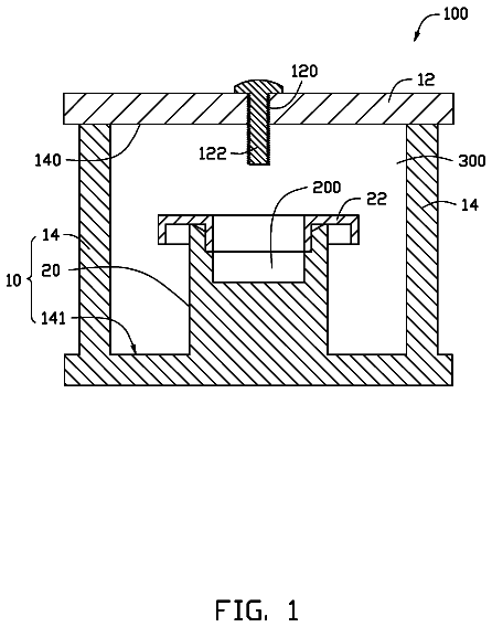
A cavity filter includes a unitarily formed piece, a cap, a cover, and a tuning adjustment screw.
US 8,624,708 B2 · Assignee: MStar Semiconductor, Inc. · Inventors: Chang; Chih Yen
Sheet 1 of 4 from the published document. All sheets in the USPTO PDF
An item positioning system is provided. The item positioning system comprises a plurality of tag readers and a control device. The plurality of tag readers generate access signals respectively and receive a response signal from a target tag. The control device adjusts transmitting power of the access signals of the tag readers, and determines a position of the target item according to whether the tag readers receive the response signal.
RFID technology is a non-contact automatic identification technology implementing a tag and a reader. A small RFID tag chip is set on or embedded in a product, and product data stored in the RFID tag chip is sent to the reader for tracking. Using RFID technology as a goods tracking system or an access control system can greatly reduce manual operations. Therefore, more and more RFID technologies are being applied to factory automation, goods sales, toll systems and vehicle identification. In a shopping mall or a supermarket, the types of goods for sale are diversified and complex. A conventional method of manually managing and searching goods needs tremendous manpower and time, and is sometimes ineffective in practice. Hence, the conventional method is not a good mechanism for managing goods. Presently, a common goods search system used in a shop or store records the position or area of
All 4 drawing sheets from the published document, cropped to the drawing.
What the patent claimed, word for word. All of it is now free to use.
This patent application is based on Taiwan, R.O.C. patent application No. 97137151 filed on Sep. 26, 2008.
The present invention relates to radio frequency identification (RFID), and more particularly, to an item positioning system using an RFID tag and a method thereof.
RFID technology is a non-contact automatic identification technology implementing a tag and a reader. A small RFID tag chip is set on or embedded in a product, and product data stored in the RFID tag chip is sent to the reader for tracking. Using RFID technology as a goods tracking system or an access control system can greatly reduce manual operations. Therefore, more and more RFID technologies are being applied to factory automation, goods sales, toll systems and vehicle identification.
In a shopping mall or a supermarket, the types of goods for sale are diversified and complex. A conventional method of manually managing and searching goods needs tremendous manpower and time, and is sometimes ineffective in practice. Hence, the conventional method is not a good mechanism for managing goods.
Presently, a common goods search system used in a shop or store records the position or area of every good in the shop. When a customer or a shop assistant wishes to search for a position or area of a certain good, he inputs the name or keyword of the good into the goods search system and obtains the exact position from the goods search system. However, if the position of the good is changed, e.g., the good is moved to another area by a customer, the customer or the shop assistant can not successfully find the good from the goods search system.
Therefore, there is a need for improving goods search systems.
An item positioning system is provided according to a first embodiment of the present invention. The item positioning system determines a position of a target item to which a target tag is attached. In practice, the target tag is a high frequency (HF) RFID tag.
The item positioning system comprises a plurality of tag readers and a control device. The tag readers correspond to a plurality of predetermined positions within a space. The tag readers generate access signals respectively and optionally receive a response signal generated by the target tag. The control device, coupled to the tag readers, optionally adjusts transmitting power of the access signals generated by the tag readers. The control device determines the position of the target item according to whether the tag readers receive the response signal.
An item positioning method is provided according to a second embodiment of the present invention. The item positioning method is used to determine a position of a target item. In this embodiment, a target tag is attached to the target item. In practice, the target tag is a HF RFID tag.
In the method, a plurality of tag readers are controlled to generate access signals respectively, and are corresponding to a plurality of predetermined positions within a space. Transmitting power of the access signals generated by the tag readers is optionally adjusted according to whether the tag readers receive a response signal generated by the target item. The position of the target item is determined according to whether the number of the tag readers receiving the response signal is smaller than a predetermined value.
In conclusion, an item positioning system according to the present invention determines whether a plurality of tag readers provided at different positions within a same space can access a target tag. Accordingly, the item positioning system according to the present invention optionally controls transmitting power of the tag readers to narrow down a range and a position of the target tag. Compared to the prior art, the item positioning system according to the invention can correctly position the position of the target tag and determine a current position of the target item. Therefore, the item positioning system of the invention may be particularly useful for purposes of searching for positions of goods in a shop, or for books in a library, among other uses.
The following description and figures are provided to better understand details and attendant advantages of the present invention.
FIG. 1 is a schematic diagram of an item positioning system in accordance with a first embodiment of the present invention.
FIG. 2 (a) and FIG. 2(b) are examples that an item positioning system positions items.
FIG. 3 (a) and FIG. 3(b) are respectively functional block diagrams of a tag reader 141 and 142 as illustrated in FIG. 1.
FIG. 4 is a flow chart of an item positioning method in accordance with a second embodiment of the present invention.
An objective of the present invention is to control transmitting power of a tag reader to narrow down the search range according to the response of the target tag and, ultimately, find the target tag.
An item positioning system is provided according to a first embodiment of the present invention. The item positioning system deployed in a convenience store is used for determining a position of a target good with an identification tag, such as a certain drink. An identification tag, such as a high frequency RFID tag, is attached to the target good. FIG. 1 shows a schematic diagram of the item position system comprising a control device 10, a transforming device 12 and sixteen tag readers 141 to 156.
For example, the control device 10 is coupled to the transforming device 12 via Ethernet, and the transforming device 12 is coupled to the tag readers 141 to 156 via a power line network or Ethernet.
In this embodiment, the tag readers 141 to 156 are respectively provided at different positions in the convenience store. For example, the tag reader 141, inserted in an electric socket, is coupled to the transforming device 12 via the power line network, and the transforming device 12 is coupled to the control device 10 via Ethernet. A function of the transforming device is to convert different signal formats between the power line network and Ethernet.
When a shop assistant of the convenience store wishes to find a current position of a target good attached with the target tag 5 by the item positioning system 1, the shop assistant operates the control device 10 to generate a control signal to each of the tag readers 141 to 156. In the process, the transforming device 12 is used to convert the control signal and transmit the converted control signal to the readers 141 to 156. When receiving the control signal respectively, each of the tag readers 141 to 156 generates an access signal and transmits the access signal within a first range as illustrated in FIG. 2 (a).
In practice, each of the tag readers 141 to 156 adjusts transmitting power of the access signal to change the transmitting range of the access signal. For example, when transmitting power of the access signal of the tag reader 141 is increased, the transmitting range of the access signal is expanded. In this embodiment, suppose that the first ranges of the tag readers 141 to 156 are the same; that is, each of the tag readers 141 to 156 transmits the access signal with the same transmitting power.
Whether the target good is in the first ranges of the access signals transmitted by the tag readers is to be further discussed below. Referring to FIG. 2 (a), when the target good with the target tag 5 is in the first range of the access signal transmitted by the tag reader device 144, the target tag 5 shall receive the access signal. According to the access signal, the target tag 5 then generates a response signal, which is subsequently received by the tag reader 144.
Having received the response signal, the tag reader 144 generates a successful access signal according to the response signal and transmits the same to the control device 10. If the control device 10 receives the successful access signal sent by the tag reader 144, it means that the tag reader 144 can access the target tag 5 attached to the target good. That is, the target tag 5 is located in the first range of the access signal of the tag reader 144.
Still referring to FIG. 2 (a), the target tag 5 attached to the target good is obviously outside the first range of the access signal of the tag reader 141. Indeed, the target tag 5 is not able to receive an access signal transmitted by the tag reader 141, and hence the target tag 5 does not generate a response signal according to the access signal of the tag reader 141. The tag reader 141 does not receive the response signal from the target tag 5. Therefore, the tag reader 141 will not transmit a successful access signal to the control device 10. If the control device 10 does not receive the successful access signal sent by the tag reader 141, it means that the tag reader 141 is not able to access the target tag 5 attached to the target good. That is, the target tag 5 is not located in the first range of the access signal of the tag reader 141.
It is apparent from the above description that, the control device 10 determines whether each of the tag readers 141 to 156 can access the target tag 5, according to whether the control device 10 receives successful access signals respectively sent by each of the tag readers 141 to 156. As shown in FIG. 2 (a), only the tag readers 143, 144, 147 and 148 can access the target tag 5. That is, the item positioning system 1 can determine an approximate position of the target tag 5, which is positioned near an intersection area of the first ranges of the tag readers 143, 144, 147 and 148.
However, the foregoing positioning result obtained by the item positioning system 1 is not accurate enough. Accordingly, the control device 10 of the item positioning system 1 adjusts transmitting power of the access signals of the tag readers according to the foregoing positioning result.
In this embodiment, only the tag readers 143, 144, 147 and 148 are able to access the target tag 5; that is, the target tag 5 is positioned near the tag readers 143, 144, 147 and 148. Therefore, in order to further narrow down the positioning range and get a more accurate positioning result, the control device 10 decreases transmitting power of the access signals of the tag readers 143, 144, 147 and 148 and sets transmitting power of access signals of other tag readers as zero. As a result, only the tag readers 143, 144, 147 and 148 transmit access signals again within second ranges.
Referring to FIG. 2 (b), transmitting power of the access signals of the tag readers 143, 144, 147 and 148 are decreased. Therefore, the second ranges are smaller than the original first ranges, i.e., access ranges of the tag readers 143, 144, 147 and 148 are further decreased to achieve an objective of more accurately positioning the target tag 5. It is assumed that the second ranges of the tag readers 141 to 156 are the same, i.e., the access signals of the tag readers 141 to 156, according to the second ranges, are supposed to have the same transmitting power.
Referring to FIG. 2 (b), the target good is located in the second range of the access signal of the tag reader 144. At this point, the target tag 5 attached to the target good receives the access signal transmitted by the tag reader 144 and generates a response signal according to the access signal. The tag reader 144 then generates a successful access signal according to the response signal and transmits the same to the control device 10. If the control device 10 receives the successful access signal sent by the tag reader 144, it means that the tag reader 144 can access the target tag 5 attached to the target good. That is, the target tag 5 is in the second range of the access signal transmitted by the tag reader device 144.
If the control device 10 does not receive the successful access signals sent back to the tag readers 143, 147 and 148, it means that the target good is outside the second ranges of the access signals transmitted by the tag readers 143, 147 and 148. Therefore, the target tag 5 attached to the target good does not receive the access signals transmitted by the tag readers 143, 147 and 148.
As mentioned above, the control device 10 only receives the successful access signal from the tag reader 144. Hence, the position of the target tag 5 is narrowed down to the second range of the tag reader 144 by the item position system 1. Accordingly, the item positioning system 1 can accurately position a correct position of the target good currently located in the convenience store.
In this embodiment, the tag reader can be provided in a general electric socket and coupled to a transforming device via the power line network. The tag reader 141 in FIG. 1 is taken as an example to be discussed below. Referring to FIG. 3 (a), the tag reader device 141 comprises a tag reader module 1412 and a power line network transmitting/receiving module 1414. The tag reader module 1412 comprises an antenna 1413. The power line network transmitting/receiving module 1414 is coupled to the transforming device 12 via the power line network. The transforming device 12 is coupled to the control device 10 via Ethernet, and hence a control signal generated by the control device is first transmitted to the transforming device 12 via Ethernet. After the signal format of the control signal is converted by the transforming device, the control signal is then transmitted to the transmitting/receiving module 1414 via the power line network. The tag reader module 1412 receives the control signal from the power line network transmitting/receiving module 1414 and sends an access signal via the antenna 1413 according to the control signal.
In addition, when receiving the response signal of the target tag 5 via the antenna 1413, the tag reader module 1412 shall generate a successful access signal and transmit the successful access signal from the power line network transmitting/receiving module 1414 to the transforming device 12 via the power line network. After the signal format of the successful access signal is converted by the transforming device 12, the successful access signal is transmitted to the control device 10 via Ethernet. Upon receiving the successful access signal, the control device 10 adjusts transmitting power of the access signal sent from the antenna 1413 of the tag reader module 1412 according to the successful access signal.
In practice, the power line network transmitting/receiving module 1414 is coupled to the tag reader module 1412 via a Serial Peripheral Interface (SPI), a universal asynchronous receiver/transmitter (UART), an Inter-Integrated Circuit (I2C) or a Universal Serial Bus (USB).
The tag reader can be coupled to the transforming device via Ethernet. The tag reader 142 in FIG. 1 is taken as an example to be discussed below. Referring to FIG. 3 (b), the tag reader 142 comprises a tag reader module 1422 and an Ethernet transmitting/receiving module 1424. The tag reader 1422 comprises an antenna 1423. The Ethernet transmitting/receiving module 1424 is coupled to a transforming device 13 via Ethernet, and the transforming device 13 is coupled to the control device 10 via Ethernet as well. Therefore, the control signal generated by the control device 10 is transmitted from the transmit device 13 to the Ethernet transmitting/receiving module 1424 via the Ethernet. The tag reader module 1422 then receives the control signal from the Ethernet transmitting/receiving module 1424 and sends an access signal via the antenna 1423 according to the control signal.
In addition, when the response signal of the target tag 5 via the antenna 1423 is received, the tag reader module 1422 generates a successful access signal and sends the same from the Ethernet transmitting/receiving module 1424 to the control device 10 through the transforming device 13 via the Ethernet. When the control device 10 receives the successful access signal, the control device 8 adjusts transmitting power of the access signal sent from the antenna 1423 of the tag reader module 1422 according to the successful access signal.
In practice, the Ethernet transmitting/receiving module 1424 is coupled to the tag reader module 1422 via an SPI, a UART, an I2C or a USB.
An item positioning method is provided according to a second embodiment of the present invention, so as to determine a position of a target item having a target tag and a plurality of tag readers corresponding to a plurality of positions within a space. FIG. 4 shows a flow chart of the item positioning method.
In this embodiment, the item positioning method begins with Step S10 of controlling each tag reader to generate and transmit an access signal within a first range. In Step S12, whether tag readers receive a response signal from the target tag is determined. Two outcomes are possible: tag readers receive the response signal or tag readers do not receive a response signal.
When a certain tag reader does not receive the response signal, Step S16 is executed. Specifically, in Step S16, it is determined that the tag reader can not access the target tag. Accordingly, no further processing is performed with respect to that tag reader. When the tag reader receives the response signal, Step S14 is executed. In Step S14, whether the number of tag readers receiving the response signal is smaller than a predetermined value is further determined.
When the determination result of Step S14 is yes, i.e., when the number of tag readers receiving the response signal is smaller than the predetermined value, it means that the positioning range is accurate enough, and Step S18 is executed. In Step S18, the position of the target item is determined according to the positions of the tag readers having received the response signal. Note that this could be based on a single tag reader.
When the determination result of Step S14 is no, i.e., when the number of tag readers receiving the response signals is not smaller than the predetermined value, it means that the positioning range is not accurate enough, and Step S20 is executed. In Step S20, transmitting power of the access signals of the tag readers having received the response signals is decreased. Step S10 is then executed again. In Step S10, the transmitting power of the tag readers that received the response signals is adjusted to transmit access signals within second ranges. That is, the transmitting power of the access signals is decreased. Hence, the second ranges of the access signals of the tag readers are smaller than the first ranges.
In conclusion, an item positioning system according to the present invention determines whether a plurality of tag readers provided at different positions within a same space can access a target tag. Accordingly, the item positioning system according to the present invention optionally controls transmitting power of the tag readers to narrow down a possible range and a position of the target tag. Compared to the prior art, the item positioning system can correctly position the position of the target tag and determine a current position of the target item. Therefore, the item position system may be particularly useful for, e.g., purposes of searching for positions of goods in a shop or books in a library.
While the invention has been described in terms of what is presently considered to be the most practical and preferred embodiments, it is to be understood that the invention need not to be limited to the above embodiments. On the contrary, it is intended to cover various modifications and similar arrangements included within the spirit and scope of the appended claims which are to be accorded with the broadest interpretation so as to encompass all such modifications and similar structures.
About 3,376 words. The USPTO PDF has it with every drawing.
Fees are due 3.5, 7.5 and 11.5 years after grant. This patent expired on January 7, 2026, so the fee marked "not paid" was the one that went unpaid.
Item Positioning System and Method Thereof
Filed Aug 2009 · published Apr 2010Item positioning system and method thereof
Filed Aug 2009 · granted Jan 2014Earlier publications, parents and continuations. None of them can still be enforced, or this patent would not be listed.
Prior art cited by the examiner or applicant. Useful when you check your own idea for novelty.
Everything on this page comes from the documents linked above.


