Lapsed, fee not paid10 drawings
Industrial Equipment · US 8,622,442 B2
Lid lock apparatus for vehicle
A lid lock apparatus for a vehicle includes a retainer, a cap, and a lock pin.
US 8,622,503 B2 · Assignee: FUJIFILM Corporation · Inventors: Sumi; Katsuto
Sheet 1 of 23 from the published document. All sheets in the USPTO PDF
An inkjet image forming apparatus includes: a liquid ejection head having an ejection surface in which a plurality of nozzles are arranged two-dimensionally; a scanning device which conveys at least one of the liquid ejection head and an image formation receiving medium on which liquid ejected from the plurality of nozzles is deposited, to cause relative movement between the image formation receiving medium and the liquid ejection head in a first direction; a motor which is a driving source for driving the scanning device; and a drive force transmission mechanism which transmits drive force generated by the motor to the scanning device, wherein: in a case where rotational non-uniformity can occur Nm times for each revolution of the motor (where Nm is a natural number), and when Pv represents a spatial period representing an amount of the relative movement in the first direction on the image formation receiving medium corresponding to 1/Nm revolution of the motor, and when OSy represents an offset distance in the first direction of a pair of nozzles which form dots that are mutually adjacent in a second direction perpendicular to the first direction on the image formation receiving medium, of the plurality of nozzles arranged two-dimensionally, then relationship of OSy.apprxeq.k.times.Pv (where k is a natural number) is satisfied.
In the field of inkjet image formation, an inkjet image formation method (single pass method) is known in which, in order to achieve high image formation resolution and high productivity, head modules comprising a plurality of nozzles arranged in a two-dimensional configuration are formed, a long head (known as a "page-wide head" or "full line type head") which covers an image formation area spanning the entire width of the paper is composed by aligning a plurality of sub-heads which are constituted by the head modules, in the paper width direction (hereinafter, called the "x direction"), and an image is formed on the paper by performing just one relative scanning action of this long head and the paper in a direction (hereinafter, called the "y direction") which is perpendicular to the x direction. A single-pass composition of this kind employs relative movement of the head and paper (a
1 of 23 drawing sheets so far from the published document, cropped to the drawing. Every sheet is in the USPTO PDF.
What the patent claimed, word for word. All of it is now free to use.
The present invention relates to an inkjet image forming apparatus, and more particularly to technology for improving image formation quality (image quality) in an inkjet image forming apparatus based on a single pass method which is equipped with an inkjet head having nozzles in a two-dimensional configuration.
In the field of inkjet image formation, an inkjet image formation method (single pass method) is known in which, in order to achieve high image formation resolution and high productivity, head modules comprising a plurality of nozzles arranged in a two-dimensional configuration are formed, a long head (known as a "page-wide head" or "full line type head") which covers an image formation area spanning the entire width of the paper is composed by aligning a plurality of sub-heads which are constituted by the head modules, in the paper width direction (hereinafter, called the "x direction"), and an image is formed on the paper by performing just one relative scanning action of this long head and the paper in a direction (hereinafter, called the "y direction") which is perpendicular to the x direction.
A single-pass composition of this kind employs relative movement of the head and paper (a paper conveyance system which holds and conveys the paper), and therefore the head and the paper are not unified (in a fixed positional relationship) and relative displacement or vibration may occur in directions other than the relative scanning direction (y direction) during the image formation process. The causes of this relative displacement and vibration include, for instance, various mechanical shocks caused internally and externally to the image forming apparatus, displacement caused by the drive system for driving various moving parts including the paper conveyance system, and so on, and such factors manifest themselves as relative vibrations between the head and paper. Of the relative vibration between the head and the paper, the vibration in the x direction in particular generates non-uniformity which causes problems of image quality in a two-dimensional nozzle arrangement.
In relation to relative vibration of the head and the paper, Japanese Patent Application Publication No. 10-235854 discloses technology for reducing image abnormalities (band-shaped "vertical stripes" extending in the paper conveyance direction (y direction)) which are caused by abnormal ejection dots, by oscillating or moving a head in a direction (x direction) perpendicular to the y direction, in an inkjet apparatus based on a single pass method employing a line head having one-dimensional arrangement of nozzles.
The apparatus composition in Japanese Patent Application Publication No. 10-235854 prevents, due to its one dimensional nozzle arrangement, problems of image quality caused by relative vibration and relative movement of the head and the paper (recording paper) in the x direction and achieves a reduction in non-uniformity by using other nozzles to compensate for recording of missing dots by making active use of the vibration in the x direction. However, in the case of a two-dimensional nozzle arrangement, as described hereinafter, a major problem which is characteristic of a two-dimensional arrangement occurs.
In a head having a two-dimensional nozzle arrangement, of the pairs of nozzles which form dots that are mutually adjacent in the x direction on the paper (or a raster created by linking dots continuously in the y direction), there are nozzle pairs which are in a positional relationship separated by a distance in the y direction, in the layout of nozzles in the head (such nozzles are called a "y-offset adjacent nozzle pair" below).
In this case, if there is relative vibration in the x direction between the head and the paper, then the pitch between the rasters recorded by the y-offset adjacent nozzle pair varies depending on the relative vibration. As a result of this, a "weighting (overlapping)" or "gap" appears between the dots (adjacent dots in the x direction) which are recorded by the y-offset adjacent nozzle pair, and the extent of this "weighting" or "gap" changes in the y direction, producing a non-uniformity which degrades the image quality. In the present specification, density non-uniformity which is caused by relative vibration or displacement in the x direction between the paper and a head having a two-dimensional nozzle arrangement in this way is called "vibration non-uniformity".
A phenomenon of this kind is described here by means of the examples in FIG. 20 to FIG. 25. FIG. 20 is one example of a two-dimensional nozzle arrangement. A black dot ".cndot." in FIG. 20 indicates a nozzle position. The horizontal axis represents a position in the x direction and the vertical axis represents a position in the y direction; a nozzle position is represented by coordinates in pixel (pix) units which are determined by the recording resolution.
As shown in FIG. 20, this two-dimensional nozzle layout has two nozzle rows separated in the y direction, and within the same row, nozzles are arranged every other 1 pix (the x-direction nozzle pitch within one row is 2 pix) and the positions of the nozzles belonging to different rows are staggered by 1 pix in the x direction with respect to each other (a so-called staggered matrix configuration). As a result of this, an image formation mode is adopted in which, a raster (scanning line) is formed on the paper every other 1 pix by the nozzle group belonging to the first row, and rasters formed by the nozzle group of the second row are embedded between the rasters formed by the nozzles of the first row. The pitch in the y direction between the first and second rows is called the offset amount of the "y-offset adjacent nozzle pair" (y-direction offset amount). Here, an example is given in which the y-direction offset amount is 500 pix. If the image formation resolution is 1200 dpi, then 500 pix is 10.6 mm.
Regarding a head having a two-dimensional nozzle arrangement as shown in FIG. 20, FIG. 21 shows one example of rasters drawn by respective nozzles in a case where there is relative vibration in the x direction between the head and paper. FIG. 21 shows a group of rasters obtained when ejection is started simultaneously from all of the nozzles and continuous ejection is performed at a prescribed droplet ejection frequency while conveying the paper at a uniform speed in the y direction. Furthermore, FIG. 22 shows an example of an image actually formed on paper in this case (a solid image; droplet ejection rate 100%). FIG. 21 and FIG. 22 are examples of a case where the single amplitude (half amplitude) of the relative vibration in the x direction is 5 .mu.m, and the period of the relative vibration is 1000 pix=21.2 mm when converted to a spatial distance on the paper in the y direction.
In FIG. 21, the raster indicated by reference numeral 1A is drawn by nozzles belonging to the lower row (first row) in FIG. 20. In FIG. 21, the raster indicated by reference numeral 2B is drawn by nozzles belonging to the upper row (second row) in FIG. 20. The raster 1A and the raster 2B are separated by the equivalent of 500 pix in the y direction. This corresponds to the y-direction offset amount between the lower row nozzle and the upper row nozzle in FIG. 20.
If it is supposed that there is no relative vibration in the x direction between the head and the paper, then the scanning lines (rasters) of the y-offset adjacent nozzle pair are straight lines which extend in perfectly straight fashion in the y direction, and the pitch between the rasters is a uniform value determined by the resolution (for example, a pitch of about 21.2 .mu.m in the case of 1200 dpi resolution).
On the other hand, if there is relative vibration in the x direction between the head and the paper, then the raster of a nozzle of the first row (reference numeral 1A) and the raster of a nozzle of the second row (reference numeral 2B) fluctuate respectively (see FIG. 21). This fluctuation of the rasters causes variation in the spatial period of the x-direction pitch between mutually adjacent rasters (1A, 2B), depending on the position in the paper conveyance direction (y direction).
As a result of this, as shown in FIG. 22, periodic non-uniformity occurs in the resulting image that is formed. More specifically, since the x-direction pitch between rasters which are mutually adjacent in the x direction varies periodically, then a "weighting" of the adjacent rasters (mutual approach of the rasters) and a "gap" in the adjacent rasters (distancing of the rasters) are repeated in the y direction, and this appears as a density non-uniformity in the image formation results on the paper.
In FIG. 22, a white-striped region 4 in which white stripes extending in the y direction are arranged roughly equidistantly in the x direction, and a black region 5 where the white stripes are interrupted in the y direction and appear darker (more dense) are repeated at 1/2 of the cycle of the vibration in the y direction (here, 500 pix).
Looking across the white-striped region 4 in the x direction, a portion where there is a white gap (white stripe) and a portion where there is no white stripe (black portion) are repeated alternately. If the white-striped portions are viewed in further detail, the gaps between white stripes (the thickness of the white stripes) are not uniform in the y direction, but rather become larger in the central portion. If the white-striped region 4 of this kind is viewed macroscopically, the density is reduced compared to the black region 5, and therefore when the image is viewed as a whole, a density non-uniformity is visible in which the density varies in the y direction (dark/light shading is repeated periodically), and therefore image quality declines.
In the description above, an example is given in which nozzles are arranged two-dimensionally in 2 rows (y direction) by N columns (x direction, where N is an integer and N.gtoreq.2), but the present problem is not limited to this nozzle arrangement and a similar problem occurs in other two-dimensional nozzle arrangements (for example, an M row.times.N column two-dimensional nozzle arrangement, where M is an integer and M.gtoreq.2).
FIG. 23 shows a case of a nozzle layout having 6 rows by N columns. Similarly to FIG. 20, if the half amplitude of the relative vibration is 5 .mu.m, then the period of the relative vibration is 1000 pix=21.2 mm in terms of a y-direction distance on the paper. FIG. 24 shows one example of rasters in a case where there is relative vibration in the x direction between the head and the paper, in a head having the nozzle arrangement in FIG. 23, and FIG. 25 is an example of an image (solid image) formed in this case.
In the case of the nozzle arrangement shown in FIG. 23, there are a total of six combinations of nozzle rows having nozzles which constitute y-offset adjacent nozzle pairs: the first row and second row, the second row and third row, the third row and fourth row, the fourth row and fifth row, the fifth row and sixth row, and the sixth row and first row. Density non-uniformity occurs due to variation in the pitch between the rasters corresponding to these respective nozzles (see FIG. 25), and of this non-uniformity, the white stripes caused by variation in the pitch between rasters formed by the pair of nozzles which are spaced furthest apart in the y direction (namely, the nozzles of the sixth row and the nozzles of the first row) are most conspicuous and this nozzle pair which have the largest offset amount have the greatest effect on image deterioration.
In this case, as shown in FIG. 25, the white-striped region 6 and the black region 7 are repeated at a vibration period (here, 1000 pix) in the y direction. In FIG. 22 and FIG. 25, the period of the vibration non-uniformity (white-striped region and black region) varies due to the following reason.
The nozzle arrangement in FIG. 22 involves an alignment of two rows as shown in FIG. 20. In this case, there are two sets of "y-offset adjacent nozzle pairs", namely, a set of "first row nozzle-second row nozzle" (hereinafter called "A set") and a set of "second row nozzle-first row nozzle" (hereinafter called "B set"). A vibration non-uniformity having a vibration period (1000 pix) occurs in the A set nozzle pair and a vibration non-uniformity having a vibration period (1000 pix) occurs in the B set nozzle pair. Since the vibration non-uniformities created by the two sets of nozzle pairs are mutually displaced by 180 degrees in terms of the phase, then the synthesized vibration non-uniformity has a period (500 pix) of 1/2 of the vibration period (see FIG. 21).
On the other hand, the case shown in FIG. 25 corresponds to the nozzle arrangement indicated in FIG. 23 (a six-row arrangement), but in this case, the "y-offset adjacent nozzle pair" is formed by only one set: "sixth row nozzle-first row nozzle", and the period of the vibration non-uniformity which appears is the vibration period (1000 pix) only (see FIG. 24).
The present invention has been contrived in view of these circumstances, an object thereof being to provide an inkjet image forming apparatus and a method of designing same, and a method of improving image formation quality, whereby it is possible to reduce deterioration in image quality due to density non-uniformity (vibration non-uniformity) caused by relative vibration between a head comprising a two-dimensional nozzle arrangement and an image formation receiving medium (recording paper, or the like).
In order to achieve the aforementioned object, the following modes of the invention are offered for example.
In order to attain an object described above, one aspect of the present invention is directed to an inkjet image forming apparatus comprising: a liquid ejection head having an ejection surface in which a plurality of nozzles are arranged two-dimensionally; a scanning device which conveys at least one of the liquid ejection head and an image formation receiving medium on which liquid ejected from the plurality of nozzles is deposited, to cause relative movement between the image formation receiving medium and the liquid ejection head in a first direction; a motor which is a driving source for driving the scanning device; and a drive force transmission mechanism which transmits drive force generated by the motor to the scanning device, wherein: in a case where rotational non-uniformity can occur Nm times for each revolution of the motor (where Nm is a natural number), and when Pv represents a spatial period representing an amount of the relative movement in the first direction on the image formation receiving medium corresponding to 1/Nm revolution of the motor, and when OSy represents an offset distance in the first direction of a pair of nozzles which form dots that are mutually adjacent in a second direction perpendicular to the first direction on the image formation receiving medium, of the plurality of nozzles arranged two-dimensionally, then relationship of OSy.apprxeq.k.times.Pv (where k is a natural number) is satisfied.
In an inkjet image forming apparatus which performs image formation by relative scanning of a liquid ejection head and an image formation receiving medium, a periodic relative vibration may be produced in synchronism with the rotation of a motor, between the liquid ejection head and the image formation receiving medium, as a result of rotational non-uniformity in the motor which is a drive source of the scanning device. If rotational non-uniformity occurs Nm times (where Nm is a natural number) with each one revolution of the motor, then a vibration appears on the image formation receiving medium at a period (Pv) corresponding to 1/Nm revolutions of the motor. On the other hand, in a two-dimensional nozzle arrangement of a liquid ejection head, the distance between nozzles in the first direction of a nozzle pair which form dots that are mutually adjacent in the second direction on the image formation receiving medium is called the offset distance and is represented by "OSy". A nozzle pair of this kind is called a "first direction offset adjacent nozzle pair".
According to this aspect of the invention, the offset distance OSy of the first direction offset adjacent nozzle pair is generally a natural number multiple of the vibration period (Pv) on the image formation receiving medium which occurs at a period corresponding to the rotational non-uniformity of the motor, and therefore the phase of the vibration causing displacement in the second direction of the dot rows (rasters) recorded on the image formation receiving medium by the nozzle pair is generally matching. Variation in the pitch in the second direction between these dot rows (rasters) is suppressed and kept to a small amount. More specifically, variation in the pitch in the second direction between dots recorded by the nozzle pair is suppressed and vibration non-uniformity is reduced.
If OSy=k.times.Pv is satisfied, then it is possible to suppress vibration non-uniformity more favorably, but a suitable effect can be obtained even if OSy/Pv diverges slightly from k (where k is a natural number). The nearer the value of OSy/Pv to a natural number, the greater the effect in suppressing vibration non-uniformity, whereas the greater the difference between OSy/Pv and a natural number k, the smaller the effect in suppressing vibration non-uniformity.
The scanning device may employ a mode where an image formation receiving medium is conveyed with respect to a stationary liquid ejection head, a mode where a liquid ejection head is moved with respect to a stationary image formation receiving medium, or a mode where both the liquid ejection head and the image formation receiving medium are moved.
Depending on the mode of the two-dimensional nozzle arrangement, there are nozzle pairs having different offset distances, amongst the first direction offset adjacent nozzle pairs, but the present invention does not require the aforementioned relationship to be established in respect of all of the nozzle pairs and a suitable effect in reducing non-uniformity is obtained provided that the aforementioned relationship is satisfied in respect of a portion of the nozzle pairs which have a large effect of vibration non-uniformity.
Desirably, the relationship of |sin {.pi.OSy/Pv}|.ltoreq.1/4 is satisfied.
As stated above, the effect in suppressing vibration non-uniformity varies depending on the value of OSy/Pv. By satisfying the relationship above, a large effect in reducing vibration non-uniformity is obtained since the half amplitude of the pitch variation of the pitch between dot rows (rasters) that are adjacent in the second direction on the image formation receiving medium can be suppressed to not greater than 1/2 of the half amplitude Av in the second direction of the relative vibration which occurs with a period corresponding to the pitch of the meshing teeth.
Desirably, a group of the plurality of nozzles arranged two-dimensionally includes the pairs of nozzles having the different offset distances, and the relationship is satisfied, with a maximum value of the different offset distances being taken as OSy.
The greater the offset distance, the greater the effect on vibration non-uniformity, and therefore if at least the maximum value of the offset distance is taken as the value of OSy, then desirably the relationship OSy.apprxeq.k.times.Pv or the relationship |sin(.pi.OSy/Pv)|.ltoreq.1/4 is satisfied.
It is possible that the liquid ejection head is formed by joining together a plurality of head modules each of which has an ejection surface in which a plurality of nozzles are arranged two-dimensionally; and when the offset distance of the pair of nozzles which spans different head modules of the plurality of head modules is represented by OSy_B, the relationship is satisfied by taking OSy_B as OSy.
According to this aspect of the invention, in a mode where one liquid ejection head (head bar) is composed by joining together a plurality of head modules, it is possible to reduce vibration non-uniformity in first direction offset adjacent nozzles pairs which span different modules. This aspect of the invention is especially useful in a composition where head modules are arranged two-dimensionally.
The plurality of head modules may be disposed in a staggered arrangement.
Desirably, the scanning device includes a medium conveyance device which conveys the image formation receiving medium, and the medium conveyance device employs a drum rotation system which holds the image formation receiving medium on a cylindrical surface of a drum and rotates the drum.
Desirably, when a diameter of the drum is represented by Ddr and a speed reduction ratio of the drive force transmission mechanism is represented by R, then Pv which indicates a period of vibration appearing on the image formation receiving medium as a result of rotation of the motor is expressed by Pv=.pi.DdrR/Nm.
The inkjet image forming apparatus may carry out image formation based on a single pass method such that the relative movement between the image formation receiving medium and the liquid ejection head is caused just once in the first direction by the scanning device to form an image on the image formation receiving medium.
Vibration non-uniformity is a particular problem in a single pass method, and therefore it is effective that this aspect of the present invention is applied to such cases. According to this aspect of the present invention, it is possible to achieve both high image formation quality and high productivity.
In order to attain an object described above, another aspect of the present invention is directed to a method of designing an inkjet image forming apparatus including: a liquid ejection head having an ejection surface in which a plurality of nozzles are arranged two-dimensionally; a scanning device which conveys at least one of the liquid ejection head and an image formation receiving medium on which liquid ejected from the plurality of nozzles is deposited, to cause relative movement between the image formation receiving medium and the liquid ejection head in a first direction; a motor which is a driving source for driving the scanning device; and a drive force transmission mechanism which transmits drive force generated by the motor to the scanning device, wherein: in a case where rotational non-uniformity can occur Nm times for each revolution of the motor (where Nm is a natural number), and when Pv represents a spatial period representing an amount of the relative movement in the first direction on the image formation receiving medium corresponding to 1/Nm revolution of the motor, and when OSy represents an offset distance in the first direction of a pair of nozzles which form dots that are mutually adjacent in a second direction perpendicular to the first direction on the image formation receiving medium, of the plurality of nozzles arranged two-dimensionally, then arrangement of the plurality of nozzles in the liquid ejection head and a speed reduction ratio of the drive force transmission mechanism are specified in such a manner that relationship of OSy.apprxeq.k.times.Pv (where k is a natural number) is satisfied.
According to this aspect of the invention, when designing an inkjet image forming apparatus, particular attention is paid to the relationship between the nozzle arrangement in the liquid ejection head (and in particular, the offset distance of the first direction offset adjacent nozzle pairs) and the speed reduction ratio of the drive force transmission mechanism, and the dimensions are adjusted and the members are selected, and the like, so as to satisfy the relationship: OSy.apprxeq.k.times.Pv (where k is a natural number). By this means, it is possible to manufacture an inkjet image forming apparatus in which vibration non-uniformity is reduced.
For example, it is possible to create a design which optimizes the speed reduction ratio of the speed reducing system with respect to a certain given nozzle arrangement. Conversely, it is also possible to create a design which optimizes the nozzle arrangement with respect to a drive force transmission mechanism having a certain given speed reduction ratio.
In order to attain an object described above, another aspect of the present invention is directed to a method of improving image formation quality of an inkjet image forming apparatus including: a liquid ejection head having an ejection surface in which a plurality of nozzles are arranged two-dimensionally; a scanning device which conveys at least one of the liquid ejection head and an image formation receiving medium on which liquid ejected from the plurality of nozzles is deposited, to cause relative movement between the image formation receiving medium and the liquid ejection head in a first direction; a motor which is a driving source for driving the scanning device; and a drive force transmission mechanism which transmits drive force generated by the motor to the scanning device, the method comprising the steps of: obtaining information indicating, in a case where rotational non-uniformity can occur Nm times for each revolution of the motor (where Nm is a natural number), a spatial period representing an amount of the relative movement in the first direction on the image formation receiving medium corresponding to 1/Nm revolution of the motor; acquiring information indicating an offset distance in the first direction of a pair of nozzles which form dots that are mutually adjacent in a second direction perpendicular to the first direction on the image formation receiving medium, of the plurality of nozzles arranged two-dimensionally; and modifying a speed reduction ratio of the drive force transmission mechanism in such a manner that relationship of OSy.apprxeq.k.times.Pv (where k is a natural number, Pv represents the obtained spatial period and OSy represents the acquired offset distance) is satisfied.
In general, there is little scope for modification in the design of a nozzle arrangement, and in many cases it is easier to change the components or the design of the drive force transmission system. Furthermore, a liquid ejection head is highly expensive compared to gear wheels and other components of a drive force transmission system. Consequently, according to this aspect of the invention, it is possible to improve the effects of vibration non-uniformity in a relatively simple fashion and at low cost, and it is possible to obtain an inkjet image forming apparatus which achieves good image formation quality. The sequence of a first step (step of obtaining information indicating the spatial period) and a second step (step of acquiring information indicating the offset distance) is not limited, and either of the steps can be carried out first.
According to the present invention, it is possible to satisfactorily reduce non-uniformity (vibration non-uniformity) appearing on an image formation receiving medium caused by a two-dimensional nozzle arrangement and rotational non-uniformity of a motor when performing relative scanning of a liquid ejection head and the image formation receiving medium. By this means, it is possible to achieve high image formation quality and high productivity.
A preferred embodiment of this invention as well as other objects and benefits thereof, will be explained in the following with reference to the accompanying drawings, in which like reference characters designate the same or similar parts throughout the figures and wherein:
FIG. 1 is an illustrative diagram showing an example of a drive force transmission mechanism between a motor and a drum;
FIG. 2 is an illustrative diagram showing a schematic view of rasters in a paper conveyance direction which are recorded by a y-offset adjacent nozzle pair;
FIG. 3 is a graph showing an example of a state where the raster pitch D(y) of the y-offset adjacent nozzle pair varies;
FIGS. 4A and 4B are illustrative diagrams showing an example of the relationship between the offset amount of a nozzle pair (OSy), the conditions of the relative vibration period (Pv) and the pitch variation between rasters;
FIG. 5 is a diagram showing an example of rasters obtained by applying an embodiment of the present invention to a head having a two-dimensional nozzle arrangement in 2 rows and N columns;
FIG. 6 is a diagram showing an example of an image (solid image) formed under the conditions shown in FIG. 5;
FIG. 7 is a diagram showing an example of rasters obtained by applying an embodiment of the present invention to a head having a two-dimensional nozzle arrangement in 6 rows and N columns;
FIG. 8 is a diagram showing an example of an image (solid image) formed under the conditions shown in FIG. 7;
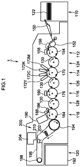
FIG. 9 is a general schematic drawing of an inkjet image forming apparatus relating to an embodiment of the present invention;
FIG. 10 is a schematic drawing of a drum rotation mechanism in the inkjet image forming apparatus shown in FIG. 9;
FIG. 11 is an enlarged perspective diagram of a drum rotation gear portion employed in an inkjet image forming apparatus according to an embodiment of the invention;
FIG. 12 is a schematic drawing showing an enlarged view of a portion of the reducing gear system in the drum rotation mechanism shown in FIG. 10;
FIG. 13 is an illustrative diagram showing a schematic diagram of the relationship between the order Nm of rotational non-uniformity of a motor and a vibration period Pv;
FIG. 14 is a diagram showing a mode where a toothed belt (timing belt) is used as a further example of a meshing transmission mechanism;
FIGS. 15A and 15B are plan view perspective diagrams showing an example of the composition of an inkjet head;
FIGS. 16A and 16B are diagrams showing examples of a head bar composed by joining together a plurality of head modules;
FIG. 17 is a cross-sectional diagram along line 17-17 in FIGS. 15A and 15B;
FIG. 18 is a block diagram showing the composition of a control system of an inkjet image forming apparatus;
FIG. 19 is an illustrative diagram of the amount of offset of a y-offset adjacent nozzle pair which spans different head modules;
FIG. 20 is a nozzle layout diagram showing an example of a two-dimensional nozzle arrangement comprising 2 rows.times.N columns;
FIG. 21 is a diagram showing rasters obtained by an inkjet image forming apparatus which uses the nozzle arrangement in FIG. 20;
FIG. 22 is a diagram showing an example of an image (solid image) formed under the conditions shown in FIG. 21;
FIG. 23 is a nozzle layout diagram showing an example of a two-dimensional nozzle arrangement comprising 6 rows.times.N columns;
FIG. 24 is a diagram showing rasters obtained by an inkjet image forming apparatus which uses the nozzle arrangement in FIG. 23; and
FIG. 25 is a diagram showing an example of an image (solid image) formed under the conditions shown in FIG. 24.
Principle of Suppressing Vibration Non-Uniformity According to Embodiments of the Invention
Firstly, the causes of vibration non-uniformity and the corresponding principles of embodiments of the present invention will be described. In the following description, the paper conveyance direction (y direction) corresponds to the "first direction" and the x direction perpendicular to this corresponds to the "second direction".
Causes of Vibration Non-Uniformity
There are following two main causes of vibration non-uniformity.
(1-a) Causes of x Direction Relative Vibration (Main Cause)
In an inkjet image forming apparatus, a motor is used as a source of drive force for a device which causes relative movement of the head and the paper. For example, in the case of an inkjet image forming apparatus based on a drum conveyance method, the rotation of the motor is transmitted to a drum via a drive force transmission system, such as a belt, pulley or gear wheels of various kinds, thus forming a composition which causes the drum to rotate. The ratio of the speed of revolution between the motor and the drum is determined by the gear reduction ratio of the drive force transmission system between the motor and the drum.
Generally, a motor has rotational non-uniformity which is synchronous with one revolution. The "rotational non-uniformity" referred to here can be regarded as harmonic non-uniformity, such as non-uniformity which occurs once during one revolution caused by the mechanical system of the motor (for example, if the output shaft of the motor is eccentric with respect to the center of rotation), or non-uniformity which occurs twice in one revolution (for example, if the cross-section of the output shaft of the motor is oval-shaped), or non-uniformity which occurs three times in one revolution due to the structure of the motor (for example, a three-phase motor). The order of this (the number of times that non-uniformity occurs in one revolution of the motor) is represented by Nm (a natural number). This rotational non-uniformity is transmitted to the drum via the drive force transmission system, and consequently appears as vibration having a uniform period on the paper (x-direction vibration, y-direction vibration). The vibration in the x-direction of the drum is especially large if using a helical gear wheel as a gear wheel.
The period Pv of the vibration appearing on the paper is determined by the gear reduction ratio R and the drum diameter Ddr, and is expressed by the following Formula. Pv=.pi.Ddr R/Nm (Nm:natural number) Formula 1
Here, the symbol "" in the Formulae represents the multiplication operator (.times.).
The calculation based on Formula 1 is described here briefly with reference to FIG. 1. The rotation transmission mechanism shown in FIG. 1 has a structure in which an endless toothed belt 28 is wound between a pulley 16 which is fixed to a shaft 14 of a motor 12 and a pulley 24 which is coupled directly to a drum 20. If the speed reduction ratio in this transmission mechanism is represented by R (for example, R=1/10), then the drum 20 performs R revolutions with each revolution of the motor. Since the circumferential length of the drum 20 is ".pi..times.Ddr", then the amount of movement (in the circumferential direction) of the circumferential surface of the drum for each revolution of the motor is ".pi..times.Ddr.times.R". Since rotational non-uniformity (relative vibration) occurs Nm times with each revolution of the motor, then the vibration period Pv on the circumferential surface of the drum (the spatial period in the circumferential direction of the drum) is a value of (.pi..times.Ddr.times.R/Nm) derived from dividing ".pi..times.Ddr.times.R" by Nm.
(1-b) Relationship Between x-Direction Vibration Period and Nozzle Arrangement (Secondary Cause)
The extent of the x-direction pitch variation .DELTA.D(y) between two scanning lines (rasters) recorded by a "y-offset adjacent nozzle pair" changes depending on the relationship between the y-direction offset amount (which is equivalent to the "offset distance") OSy of the "y-offset adjacent nozzle pair" arising from the nozzle arrangement in the head, and the period Pv of the x-direction relative vibration on the paper (Pv being obtained by converting the period of rotation non-uniformity of the motor to a spatial period in the y direction on the paper).
FIG. 2 shows an enlarged schematic view of rasters (scanning lines) in the paper conveyance direction which are recorded by a y-offset adjacent nozzle pair. For the sake of simplicity, in the illustration in FIG. 2, the longitudinal/lateral dimensional ratio is distorted (deformed) in order to emphasize the amount of fluctuation of the rasters.
The horizontal direction in FIG. 2 corresponds to the lengthwise direction of the long inkjet head (bar) (called the "x direction"), and the vertical direction corresponds to the paper conveyance direction (direction of relative movement of the head and the paper, called the "y direction"). The line R_A having the waveform shown on the left-hand side in FIG. 2 indicates a raster produced by one nozzle of a y-offset adjacent nozzle pair (called "nozzle A" here), and the line R_B having the waveform shown on the right-hand side of FIG. 2 indicates a raster produced by the other nozzle of the pair (called "nozzle B" here). Rasters are recorded by dot rows created by a continuous sequence of dots formed by liquid droplets which are deposited on paper by performing continuous droplet ejection at a uniform cycle (ejection frequency) from the nozzles A and B while conveying the paper at a uniform speed in the y direction. The ejection frequency and the paper conveyance speed are specified on the basis of the image formation resolution in the y direction, and the x-direction distance between the nozzles A and B is specified on the basis of the image formation resolution in the x direction.
As FIG. 2 reveals, the raster pitch D(y) between the rasters of the y-offset adjacent nozzle pair changes with the relative vibration between the head and the paper. The amount of change (variation) .DELTA.D(y) in this pitch D(y) is expressed as shown below in terms of the y-direction offset amount OSy, the relative vibration period Pv, and the (half) amplitude of the relative vibration in the x direction, Av.
.DELTA..times..times..function..times..times..theta..function..times..the- ta..function..times..pi..times..times..pi..times..theta..function..times..- pi..times..times. ##EQU00001##
Furthermore, the maximum value .DELTA.Dmax of the raster pitch variation is expressed as follows on the basis of Formula 2. .DELTA.Dmax=max|.DELTA.D(y)|=2Av|sin {.pi.OSy/Pv}| Formula 3
In Formula 2 and Formula 3, the multiplication symbol (.times.) is written as "". Here, .DELTA.Dmax is the amplitude of the raster pitch variation, and the value thereof is determined by Av, OSy and Pv. In other words, .DELTA.Dmax is a constant component with respect to y (a value which is independent of y). On the other hand, the element "cos {.theta.(y)+.pi.OSy/Pv}" in Formula 2 is a variable component which varies with y.
Calculation of Formula 2
If there is relative variation between the paper and the head, then the rasters drawn on the paper by a y-offset adjacent nozzle pair in the head fluctuate (undulate) with the period of that relative variation. As a result of this, as shown in FIG. 2, the x-direction pitch D(y) between the rasters varies depending on the position y in the paper conveyance direction (as a function of y).
The position (x-direction position) of the raster recorded by one nozzle A of the y-offset adjacent nozzle pair under consideration varies with a half amplitude Av about the ideal position (reference position x.sub.1), and therefore this vibration is represented by a triangular function, and when the phase component of the vibration is represented by .theta.(y), the amount of variation .DELTA.X.sub.A in the position X.sub.A of the raster produced by the nozzle A is expressed as follows as a function of y. .DELTA.X.sub.A=X.sub.A(y)-x.sub.1=Av sin {.theta.(y)} Formula 4
Similarly, the position of the raster (x direction position) recorded by the other nozzle B of the y-offset adjacent nozzle pair under consideration varies with a half amplitude Av about the ideal position (reference position x.sub.2), and furthermore since there is an initial phase difference (2.pi.OSy/Pv) corresponding to the y-direction offset amount OSy between the nozzle A and the nozzle B, then the amount of variation .DELTA.X.sub.B of the position of the raster X.sub.B produced by nozzle B is expressed as follows as a function of y. .DELTA.X.sub.B=X.sub.B(y)-x.sub.2=sin {.theta.(y)+2.pi.OSy/Pv} Formula 5
The description continues in the full USPTO document.
About 6,453 words. The USPTO PDF has it with every drawing.
Fees are due 3.5, 7.5 and 11.5 years after grant. This patent expired on January 7, 2026, so the fee marked "not paid" was the one that went unpaid.
INKJET IMAGE FORMING APPARATUS, METHOD OF DESIGNING SAME AND METHOD OF IMPROVING IMAGE FORMATION QUALITY
Filed Mar 2011 · published Sep 2011Inkjet image forming apparatus, method of designing same and method of improving image formation quality
Filed Mar 2011 · granted Jan 2014Earlier publications, parents and continuations. None of them can still be enforced, or this patent would not be listed.
Prior art cited by the examiner or applicant. Useful when you check your own idea for novelty.
Everything on this page comes from the documents linked above.