 Lapsed, fee not paid3 drawings
Vehicles & Drones · US 8,621,839 B2
Gas turbine engine breather exhaust oil collector
A gas turbine engine oil system has an air-oil separator for removing air from an air/oil mixture.
US 8,621,847 B2 · Assignee: GM Global Technology Operations LLC · Inventors: Gonze; Eugene V. et al.
Sheet 1 of 3 from the published document. All sheets in the USPTO PDF
An exhaust treatment system for an engine includes a selective catalyst reduction (SCR) treatment module that controls a valve and an air pump to deliver air to an SCR catalyst in response to the engine turning off. An SCR loading module controls the valve and the air pump to deliver air to an exhaust manifold and controls a dosing system to deliver a dosing agent upstream of the SCR catalyst when a temperature of the SCR catalyst is less than a temperature threshold and the SCR catalyst is not saturated with ammonia.
The background description provided herein is for the purpose of generally presenting the context of the disclosure. Work of the presently named inventors, to the extent it is described in this background section, as well as aspects of the description that may not otherwise qualify as prior art at the time of filing, are neither expressly nor impliedly admitted as prior art against the present disclosure. A selective catalytic reduction (SCR) catalyst may be used to reduce emissions in an engine. In an SCR process, nitrogen oxide (NO.sub.x) reacts with a reductant that is injected by a dosing system into an exhaust stream. The reductant is adsorbed onto the SCR catalyst. The injected dosing agent (e.g., urea) decomposes to form ammonia (NH.sub.3). The NH.sub.3 is the reductant utilized to react with the NO.sub.x, reducing it to nitrogen (N.sub.2) and water (H.sub.2O). The SCR process typ
1 of 3 drawing sheets so far from the published document, cropped to the drawing. Every sheet is in the USPTO PDF.
What the patent claimed, word for word. All of it is now free to use.
The present disclosure relates to exhaust treatment systems and, more particularly, to engine off ammonia (NH.sub.3) selective catalytic reduction (SCR) nitrogen oxide (NO.sub.x) adsorption systems.
The background description provided herein is for the purpose of generally presenting the context of the disclosure. Work of the presently named inventors, to the extent it is described in this background section, as well as aspects of the description that may not otherwise qualify as prior art at the time of filing, are neither expressly nor impliedly admitted as prior art against the present disclosure.
A selective catalytic reduction (SCR) catalyst may be used to reduce emissions in an engine. In an SCR process, nitrogen oxide (NO.sub.x) reacts with a reductant that is injected by a dosing system into an exhaust stream. The reductant is adsorbed onto the SCR catalyst. The injected dosing agent (e.g., urea) decomposes to form ammonia (NH.sub.3). The NH.sub.3 is the reductant utilized to react with the NO.sub.x, reducing it to nitrogen (N.sub.2) and water (H.sub.2O).
The SCR process typically requires relatively high exhaust temperatures (e.g., greater than 200.degree. C.). At cold start and at low load operating conditions, engines may generate exhaust with cool exhaust temperatures (e.g., below 200.degree. C.). Accordingly, during a cold start phase the highest temperature of the SCR catalyst may be lower than the temperature required to make the SCR catalyst active in reducing NO.sub.x emission.
An exhaust treatment system for an engine includes a selective catalyst reduction (SCR) treatment module that controls a valve and an air pump to deliver air to an SCR catalyst in response to the engine turning off. An SCR loading module controls the valve and the air pump to deliver air to an exhaust manifold and controls a dosing system to deliver a dosing agent upstream of the SCR catalyst when a temperature of the SCR catalyst is less than a temperature threshold and the SCR catalyst is not saturated with ammonia.
In other features, a method of operating an exhaust treatment system for an engine includes controlling a valve and an air pump to deliver air to an SCR catalyst in response to the engine turning off. The method includes controlling the valve and the air pump to deliver air to an exhaust manifold. The method includes controlling a dosing system to deliver a dosing agent upstream of the SCR catalyst when a temperature of the SCR catalyst is less than a temperature threshold and the SCR catalyst is not saturated with ammonia.
Further areas of applicability of the present disclosure will become apparent from the detailed description provided hereinafter. It should be understood that the detailed description and specific examples are intended for purposes of illustration only and are not intended to limit the scope of the disclosure.
The present disclosure will become more fully understood from the detailed description and the accompanying drawings, wherein:
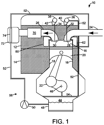
FIG. 1 is a functional block diagram of an example vehicle system including an exhaust treatment system in accordance with the present disclosure;
FIG. 2 is a functional block diagram of an example control module in accordance with the present disclosure; and
FIG. 3 is a flow diagram of an example method of operating an exhaust treatment system in accordance with the present disclosure.
The following description is merely illustrative in nature and is in no way intended to limit the disclosure, its application, or uses. For purposes of clarity, the same reference numbers will be used in the drawings to identify similar elements. As used herein, the phrase at least one of A, B, and C should be construed to mean a logical (A or B or C), using a non-exclusive logical or. It should be understood that steps within a method may be executed in different order without altering the principles of the present disclosure.
As used herein, the term module may refer to, be part of, or include an Application Specific Integrated Circuit (ASIC); an electronic circuit; a combinational logic circuit; a field programmable gate array (FPGA); a processor (shared, dedicated, or group) that executes code; other suitable components that provide the described functionality; or a combination of some or all of the above, such as in a system-on-chip. The term module may include memory (shared, dedicated, or group) that stores code executed by the processor.
The term code, as used above, may include software, firmware, and/or microcode, and may refer to programs, routines, functions, classes, and/or objects. The term shared, as used above, means that some or all code from multiple modules may be executed using a single (shared) processor. In addition, some or all code from multiple modules may be stored by a single (shared) memory. The term group, as used above, means that some or all code from a single module may be executed using a group of processors or a group of execution engines. For example, multiple cores and/or multiple threads of a processor may be considered to be execution engines. In various implementations, execution engines may be grouped across a processor, across multiple processors, and across processors in multiple locations such as multiple servers in a parallel processing arrangement. In addition, some or all code from a single module may be stored using a group of memories.
An exhaust treatment system according to the present disclosure includes an air pump with an air valve, a three-way catalyst (TWC) with palladium-containing perovskite-based and/or platinum containing alumina-based catalysts, a dosing injector, a temperature sensor, and a NO.sub.x sensor disposed upstream from a selective catalyst reduction (SCR) catalyst. During an engine start-up period, the TWC converts NO to NO.sub.2 at a temperature less than the reduction temperature. The SCR catalyst is not able to effectively reduce the NO.sub.2 into N.sub.2 and H.sub.2O during the engine start-up period. Instead, the SCR catalyst stores NO.sub.2 during the engine start-up period. Ammonia (NH.sub.3) reduces the NO.sub.2 to nitrogen (N.sub.2) and water (H.sub.2O) after the reduction temperature is exceeded.
The SCR catalyst may store more NH.sub.3 at a predetermined storage temperature than at the reduction temperature. The predetermined storage temperature is less than the reduction temperature. For example, the reduction temperature may be about 200.degree. C., and the predetermined storage temperature may be about 150.degree. C. When the engine is shut down, the air valve diverts ambient air from the air pump to the SCR catalyst. When the SCR catalyst cools to less than the predetermined storage temperature, the air valve diverts the ambient air through the engine exhaust. The engine, the TWC, and an exhaust manifold heat the ambient air. The heated air has a temperature at least as high as the reduction temperature. The air pump delivers the heated air and dosing agent from the dosing injector to the SCR catalyst.
The dosing agent decomposes in the heated air to become two molecules of NH.sub.3 for every molecule of the dosing agent in the presence of water. The SCR catalyst adsorbs the NH.sub.3. When the SCR catalyst is saturated with NH.sub.3, the air pump turns off. The NH.sub.3 stored on the SCR catalyst increases the capacity of the SCR catalyst to reduce NO.sub.x after a cold start. Accordingly, the storage of NH.sub.3 on the SCR catalyst provides improved emissions without using additional fuel.
Referring to FIG. 1, an example of a vehicle system 10 including an exhaust treatment system according to the present disclosure is shown. Air is provided to an engine 14 through an air intake system 16. A fuel delivery system 18 provides fuel to the engine 14. Exhaust is produced through the combustion process and is expelled from the engine 14 into an exhaust manifold 20. The exhaust treatment system 12 receives the exhaust from the engine 14 through the exhaust manifold 20 and treats the exhaust to reduce NO.sub.x before the exhaust is released into the atmosphere.
A control module 22 communicates with an engine on/off sensor 24. The engine on/off sensor 24 may be any device indicating a difference in a signal when the engine 14 is on or off. For example only, the engine on/off sensor 24 may be an ignition voltage shut off sensor or an engine speed sensor. The control module 22 determines when the engine 14 is off based on the signal from the engine on/off sensor 24. The control module 22 operates the exhaust treatment system 12 based on the engine on/off sensor 24 and one or more other sensors within the exhaust treatment system 12.
The exhaust treatment system 12 includes a three-way catalyst (TWC) 26 and a first selective catalytic reduction (SCR) catalyst 28. The TWC 26 oxidizes hydrocarbons in the exhaust upstream of the first SCR catalyst 28. The TWC 26 enhances NO.sub.x adsorption efficiency at low temperatures by partially converting NO contained in the exhaust into NO.sub.2.
A dosing system 32 with a dosing valve 34 and a dosing injector 36 is provided upstream of the first SCR catalyst 28. The dosing injector 36 injects the dosing agent into the exhaust stream. An air pump 38 with an air valve 40 is arranged such that the air valve 40 allows the air to be provided into the exhaust manifold 20 or between the dosing system 32 and the first SCR catalyst 28. The dosing system 32 adds the dosing agent to the exhaust stream. The heated air decomposes the dosing agent into NH.sub.3. The NH.sub.3 adsorbs onto the first SCR catalyst 28.
A first NO.sub.x sensor 30 is provided upstream of the first SCR catalyst 28 and downstream of the TWC 26. The first NO.sub.x sensor 30 is immediately upstream of the first SCR catalyst 28 and provides a NO.sub.x signal to the control module 22. A first SCR temperature sensor 42 is immediately upstream of the first SCR catalyst 28 and provides a temperature signal to the control module 22. The temperature signal indicates a temperature of the first SCR catalyst 28.
The first SCR catalyst 28 removes nitrogen oxides (NO.sub.x) in the exhaust through a chemical reaction between the exhaust, the reductant, and a catalyst on the first SCR catalyst 28. The heated air causes the dosing agent to decompose into NH.sub.3 and hydro-cyanic acid (HNCO). The HNCO further decomposes (e.g., hydrolizes) in the presence of the reduction temperature into water and NH.sub.3. The NH.sub.3 adsorbs onto the first SCR catalyst 28. The adsorbed NH.sub.3 reacts with NO.sub.x in the exhaust to form H.sub.2O and N.sub.2. The first SCR catalyst 28 may effectively convert NO.sub.x into H.sub.2O and N.sub.2 at a reduction temperature. The reduction temperature may depend on a number of factors, including but not limited to, the first SCR catalyst 28 composition and density, sizes of the canisters for the TWC 26, and/or fuel composition. The reduction temperature may be, for example only, about 200.degree. C.
Additionally, the first SCR catalyst 28 may store more NH.sub.3 as the temperature of the first SCR catalyst 28 is lowered. After the engine 14 turns off, the control module 22 activates an air pump 38 and opens the air valve 40. The air pump 38 provides ambient air to the first SCR catalyst 28, lowering the temperature of the first SCR catalyst 28.
When the temperature of the first SCR catalyst 28 is less than the predetermined storage temperature, the control module 22 directs the air valve 40 and the air pump 38 to provide ambient air through the exhaust manifold 20 to the first SCR catalyst 28. The ambient air is heated by air from the engine 14 and the exhaust manifold 20. The heated air has a temperature greater than the reduction temperature. The control module 22 directs the dosing system 32 to provide the dosing agent to the heated air. The heated air is hot enough to allow the dosing agent to decompose into NH.sub.3 and HNCO, and to allow the HNCO in the presence of water to further decompose into NH.sub.3 and CO.sub.2. The NH.sub.3 is absorbed by the first SCR catalyst 28, increasing the capacity of the SCR catalyst to reduce NO.sub.x after a cold start. The air pump 38 stops providing the heated air and the dosing system 32 stops providing the dosing agent when the first SCR catalyst 28 is saturated with NH.sub.3 and/or the dosing agent does not decompose.
After the cold start, the stored NH.sub.3 allows more NO.sub.2 storage on the first SCR catalyst 28. When the reduction temperature is met, the stored NH.sub.3 and the stored NO.sub.x may be reduced to N.sub.2 and H.sub.2O. It may be appreciated that a plurality (e.g., n) of SCR catalysts in series may also be used. An nth SCR catalyst 44 with an nth NO.sub.x sensor 46 and an nth SCR temperature sensor 48 is shown. The nth NO.sub.x sensor 46 and the nth SCR temperature sensor 48 communicate with the control module 22. When the engine 14 is on, the nth SCR catalyst 44 has a lower temperature than the first SCR catalyst 28. When the first SCR catalyst 28 has a temperature less than the predetermined temperature, the nth SCR catalyst 44 may store NH.sub.3.
The NO.sub.x signals received from the NO.sub.x sensors 30 and 46 may indirectly indicate the concentration of the NH.sub.3 in the first SCR catalyst 28. For example, because the amount of the dosing agent injected (and other measured values such as the NO.sub.x sensed before and after the SCR 28) is known, the concentration of the NH.sub.3 in the first SCR catalyst 28 may be determined. For example only, the concentration of the NH.sub.3 may be modeled or estimated based on the amount of the dosing agent injected and the signals provided by the NO.sub.x sensors 30 and 46.
Referring to FIG. 2, a functional block diagram of an example control module 22 is shown. The control module 22 includes an engine off determination module 50, an SCR treatment module 52, an SCR loading module 54, a decomposition determination module 56, an air control module 58, and a dosing control module 60.
The engine off determination module 50 generates an engine off indicator based on an engine on/off signal from the engine on/off sensor 24. The engine off indicator indicates when the engine 14 turns off. When the engine 14 turns off, the engine off determination module 50 generates the engine off indicator. The engine off determination module 50 provides the engine off indicator to the SCR treatment module 52.
The SCR treatment module 52 generates a storage temperature indicator based on a temperature signal from the first SCR temperature sensor 42 and the predetermined storage temperature. When the engine 14 is off, the SCR treatment module 52 generates a storage temperature indicator based on the temperature signal and the predetermined storage temperature. The storage temperature indicator indicates whether the temperature of the first SCR catalyst 28 is less than the predetermined storage temperature.
The SCR loading module 54 generates an NH.sub.3 saturation indicator based in part on the NO.sub.x signals. For example, as described above in FIG. 1, the NO.sub.x signals in combination with the amount of dosing agent injected and/or other variables may indicate the NH.sub.3 present in the first SCR catalyst 28. The NH.sub.3 saturation indicator indicates the saturation of the reductant onto the first SCR catalyst 28. The SCR loading module 54 may compare the NH.sub.3 present in the first SCR catalyst 28 to a saturation value. The saturation value may correspond to the NH.sub.3 present in the first SCR catalyst 28, which is saturated. The saturation value depends on a number of factors, including, but not limited to, the first SCR catalyst 28 composition, density, and size.
The decomposition determination module 56 generates a decomposition indicator based on a plurality of the NO.sub.x signals. The decomposition indicator indicates whether the dosing agent is decomposing into NH.sub.3 and CO.sub.2. The decomposition determination module 56 compares a plurality of NO.sub.x signals over a predetermined time period to determine whether the dosing agent is decomposing. For example, the decomposition determination module 56 may determine that the reductant does is not decomposing when there is no increase of NH.sub.3 after the dosing agent is added.
The air control module 58 controls the air pump 38 and the air valve 40 based on the storage temperature indicator, the NH.sub.3 saturation indicator, and the decomposition indicator. The air control module 58 activates the air pump 38 and directs the air valve 40 to deliver ambient air to the first SCR catalyst 28 when the storage temperature indicator indicates that the temperature of the first SCR catalyst 28 is greater than the predetermined storage temperature. The air control module 58 activates the air pump 38 and directs the air valve 40 to deliver engine air into the exhaust when the storage temperature indicator indicates that the temperature of the first SCR catalyst 28 is less than the predetermined storage temperature. The air control module 58 turns off the air pump 38 when the decomposition indicator indicates the reductant is not reduced and/or the NH.sub.3 saturation indicator indicates the first SCR catalyst 28 is saturated.
The dosing control module 60 controls the dosing system 32 based on the NH.sub.3 saturation indicator and the decomposition indicator. The dosing control module 60 commands delivery of the dosing agent when the decomposition indicator indicates that the dosing agent is reduced and the NH.sub.3 saturation indicator indicates that the first SCR catalyst 28 is not saturated. For example, the dosing control module 60 may activate the dosing system when the dosing agent decomposes and the first SCR catalyst 28 is not saturated.
Referring to FIG. 3, flow chart depicting an example method 100 of operating the exhaust treatment system 12 is shown. The method 100 begins at 102. At 104, the method 100 determines whether the engine 14 is off. If no, the method 100 ends at 118. If yes, the method 100 proceeds to 106. At 106, the method 100 determines whether the temperature of the first SCR catalyst 28 is less then the predetermined storage temperature. If no, the method 100 proceeds to 108. If yes, the method 100 proceeds to 110. At 108, the method 100 activates the air pump 38 and the air valve delivers ambient air to the first SCR catalyst 28. At 110, the method 100 determines whether the first SCR catalyst 28 is saturated with NH.sub.3. If yes, the method 100 proceeds to 116. If no, the method 100 proceeds to 112. At 112, the method 100 diverts air from the air pump 38 to the engine exhaust and injects the dosing agent into the exhaust. At 114, the method 100 determines whether the dosing agent is decomposing. If no, the method 100 proceeds to 116. If yes, the method 100 returns to 110. At 116, the method 100 turns the air pump off and ends at 118.
The broad teachings of the disclosure can be implemented in a variety of forms. Therefore, while this disclosure includes particular examples, the true scope of the disclosure should not be so limited since other modifications will become apparent to the skilled practitioner upon a study of the drawings, the specification, and the following claims.
About 3,201 words. The USPTO PDF has it with every drawing.
Fees are due 3.5, 7.5 and 11.5 years after grant. This patent expired on January 7, 2026, so the fee marked "not paid" was the one that went unpaid.
ENGINE OFF NH3 BASED SELECTIVE CATALYTIC REDUCTION NOX ADSORBER
Filed Sep 2011 · published Mar 2013Engine off NH.sub.3 based selective catalytic reduction NO.sub.X adsorber
Filed Sep 2011 · granted Jan 2014Earlier publications, parents and continuations. None of them can still be enforced, or this patent would not be listed.
Prior art cited by the examiner or applicant. Useful when you check your own idea for novelty.
Everything on this page comes from the documents linked above.