 Lapsed, fee not paid8 drawings
Vehicles & Drones · US 8,620,496 B2
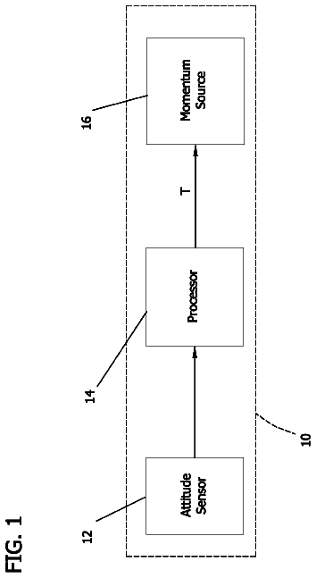
Systems and method of controlling a spacecraft using attitude sensors
A system for damping nutation and removing wobble of a spacecraft spinning about a given axis is provided.
US 8,620,508 B2 · Assignee: Honda Motor Co., Ltd. · Inventors: Akutsu; Shigemitsu et al.
Sheet 1 of 109 from the published document. All sheets in the USPTO PDF
A hybrid vehicle is driven by a power unit which includes: a first rotating machine including a first rotor, a first stator, and a second rotor, wherein the number of magnetic poles generated by an armature row of the first stator and one of the first rotor and the second rotor are connected to a drive shaft; a power engine, wherein an output shaft of the power engine is connected to the other of the first rotor and the second rotor; a second rotating machine; a capacitor; and a transformer that steps up an output voltage of the capacitor. The hybrid vehicle includes: a voltage demand calculator that calculates a voltage demand required for each of the first rotating machine and the second rotating machine in accordance with an operating condition of the hybrid vehicle; a step-up execution determining unit that allows the transformer to step up the voltage, when at least one of the voltage demand of the first rotating machine and the voltage demand of the second rotating machine is higher than a first threshold value; and a controller that controls the transformer in accordance with the result determined by the step-up execution determining unit. Accordingly, it is possible to achieve reduction in the size and cost of the power unit and enhance the driving efficiency of the power unit.
Conventionally, as the power unit of this kind, a power unit disclosed in Patent Document 1, for example, is known. This power unit is for driving left and right drive wheels of a vehicle, and is equipped with an internal combustion engine, which is a motive power source, and a transmission connected to the internal combustion engine and the drive wheels. The transmission includes first and second planetary gear units of a general single pinion type and first and second rotating machines each having a rotor and a stator. As shown in FIG. 109, the first planetary gear unit has a first ring gear, a first carrier, and a first sun gear which are mechanically connected to the internal combustion engine, a second carrier of the second planetary gear unit, and the first rotating machine, respectively. The second planetary gear unit has a second sun gear, a second carrier, and a second ring gear
1 of 109 drawing sheets so far from the published document, cropped to the drawing. Every sheet is in the USPTO PDF.
What the patent claimed, word for word. All of it is now free to use.
The present invention relates to a hybrid vehicle driven by a power unit for driving driven parts.
Conventionally, as the power unit of this kind, a power unit disclosed in Patent Document 1, for example, is known. This power unit is for driving left and right drive wheels of a vehicle, and is equipped with an internal combustion engine, which is a motive power source, and a transmission connected to the internal combustion engine and the drive wheels. The transmission includes first and second planetary gear units of a general single pinion type and first and second rotating machines each having a rotor and a stator.
As shown in FIG. 109, the first planetary gear unit has a first ring gear, a first carrier, and a first sun gear which are mechanically connected to the internal combustion engine, a second carrier of the second planetary gear unit, and the first rotating machine, respectively. The second planetary gear unit has a second sun gear, a second carrier, and a second ring gear which are mechanically connected to the second rotating machine, the drive wheels, and the first rotating machine, respectively. Moreover, the first and second rotating machines are electrically connected to each other through a controller. It should be noted that in FIG. 109, mechanical connections between elements are indicated by solid lines, and electrical connections therebetween are indicated by one-dot chain lines. Moreover, flows of motive power and electric power are indicated by thick lines with arrows.
In the conventional power unit configured as above, during traveling of the vehicle, the motive power from the internal combustion engine is transmitted to the drive wheels, for, example, in the following manner. That is, as shown in FIG. 109, the motive power from the internal combustion engine is transmitted to the first ring gear, and is then combined with motive power transmitted to the first sun gear, as described later. This combined motive power is transmitted to the second carrier through the first carrier. Moreover, in this case, electric power is generated by the second rotating machine, and the generated electric power is supplied to the first rotating machine through the controller. In accordance with the electric power generation, part of the combined motive power transmitted to the second carrier is distributed to the second sun gear and the second ring gear, and the remainder of the combined motive power is transmitted to the drive wheels. The motive power distributed to the second sun gear is transmitted to the second rotating machine, and the motive power distributed to the second ring gear is transmitted to the first sun gear through the first rotating machine. Furthermore, the motive power of the first rotating machine generated along with the above-described supply of the electric power is transmitted to the first sun gear.
Patent Document
[Patent Document 1] U.S. Pat. No. 6,478,705
Problem to be Solved by the Invention
In a conventional power unit, not only the first and second rotating machines but also at least two planetary gear units for distributing and combining motive power are indispensable for the construction thereof, and this increases the size of the power unit by a corresponding extent. Moreover, as described above, in the conventional power unit, motive power is recirculated through a path formed by the first carrier.fwdarw.the second carrier.fwdarw.the second ring gear.fwdarw.the first rotating machine.fwdarw.the first sun gear.fwdarw.the first carrier, and a path formed by the first carrier.fwdarw.the second carrier.fwdarw.the second sun gear.fwdarw.the second rotating machine.fwdarw.the first rotating machine.fwdarw.the first sun gear.fwdarw.the first carrier. This recirculation of the motive power causes very large combined motive power from the first ring gear and the first sun gear to pass through the first carrier and then pass through the second carrier as it is, so that in order to withstand the above large combined motive power, it is inevitable that there be an increase in the size of the first and second planetary gear units, which results in the further increased size and costs of the power unit. Moreover, in accordance with the increases in the size of the above power unit and the motive power passing through the power unit, losses generated in the power unit are also increased to decrease the driving efficiency of the power unit.
An object of the present invention is to provide a hybrid vehicle driven by a power unit which is capable of attaining reduction of the size and costs of the power unit and enhancing the driving efficiency thereof.
Means for Solving the Problem
In order to achieve the object, a hybrid vehicle of the invention as claimed in claim 1 is driven by a power unit. The power unit comprises: a first rotating machine (for example, first rotating machine 21 or first rotating machine 10 in the embodiment) comprising: a first rotor (for example, A1 rotor 24, first rotor 14 in the embodiment) comprising a magnetic pole row arranged in a circumferential direction, wherein the magnetic pole row has a plurality magnetic poles and the adjacent magnetic poles have different polarities; a first stator (for example, stator 23, stator 16 in the embodiment) disposed to face the first rotor in a radial direction and comprising an armature row comprising a plurality of armatures arranged in the circumferential direction, wherein a rotating magnetic field moving in the circumferential direction is generated by a change in magnetic poles generated by the plurality of armatures; and a second rotor (for example, A2 rotor 25, second rotor 15 in the embodiment) disposed between the first rotor and the first stator and comprising a plurality of soft magnetic material elements arranged in the circumferential direction with a gap therebetween, wherein the ratio between the number of magnetic poles generated by the armature row of the first stator, the number of magnetic poles of the magnetic pole row of the first rotor, the number of the soft magnetic material elements of the second rotor is set to 1:m:(1+m)/2 (m.noteq.1), and one of the first rotor and the second rotor is connected to a drive shaft; a power engine (for example, engine 3 in the embodiment), wherein an output shaft of the power engine is connected to the other of the first rotor and the second rotor; a second rotating machine (for example, second rotating machine 31, first planetary gear unit PS1 and rotating machine 101, second rotating machine 20 in the embodiment) configured to exchange a motive power with the drive shaft and to exchange an electric power with the first rotating machine; a capacitor (for example, battery 43, battery 33 in the embodiment) configured to exchange an electric power between the first rotating machine and the second rotating machine; and a transformer (for example, VCU 44 in the embodiment) that steps up a voltage when exchanging an electric power between the capacitor and at least one of the first rotating machine and the second rotating machine. The hybrid vehicle comprises: a voltage demand calculator (for example, first voltage demand calculator 63, second voltage demand calculator 64 in the embodiment) that calculates a voltage demand required for each of the first rotating machine and the second rotating machine in accordance with an operating condition of the hybrid vehicle; a step-up execution determining unit (for example, step-up execution determining unit 65 in the embodiment) that allows the transformer to step up the voltage, when at least one of the voltage demand of the first rotating machine and the voltage demand of the second rotating machine is higher than a first threshold value, wherein the first threshold value is set in accordance with an output voltage of the capacitor; and a controller (for example, ECU 2 in the embodiment) that controls the transformer in accordance with the result determined by the step-up execution determining unit.
In the hybrid vehicle of the invention as claimed in claim 2, the step-up execution determining unit that allows the transformer to stop stepping-up the voltage, when both the voltage demand of the first rotating machine and the voltage demand of the second rotating machine is lower than a second threshold value lower than the first threshold value during the step-up operation of the transformer.
In the hybrid vehicle of the invention as claimed in claim 3, the controller controls the transformer to step-up the voltage in accordance with higher one of the voltage demand of the first rotating machine and the voltage demand of the second rotating machine.
A hybrid vehicle of the invention as claimed in claim 4 is a hybrid vehicle driven by a power unit. The power unit comprises: a first rotating machine (for example, first rotating machine 21 or first rotating machine 10 in the embodiment) comprising: a first rotor (for example, A1 rotor 24, first rotor 14 in the embodiment) comprising a magnetic pole row arranged in a circumferential direction, wherein the magnetic pole row has a plurality magnetic poles and the adjacent magnetic poles have different polarities; a first stator (for example, stator 23, stator 16 in the embodiment) disposed to face the first rotor in a radial direction and comprising an armature row comprising a plurality of armatures arranged in the circumferential direction, wherein a rotating magnetic field moving in the circumferential direction is generated by a change in magnetic poles generated by the plurality of armatures; and a second rotor (for example, A2 rotor 25, second rotor 15 in the embodiment) disposed between the first rotor and the first stator and comprising a plurality of soft magnetic material elements arranged in the circumferential direction with a gap therebetween, wherein the ratio between the number of magnetic poles generated by the armature row of the first stator, the number of magnetic poles of the magnetic pole row of the first rotor, the number of the soft magnetic material elements of the second rotor is set to 1:m:(1+m)/2 (m.noteq.1), and one of the first rotor and the second rotor is connected to a drive shaft; a power engine (for example, engine 3 in the embodiment), wherein an output shaft of the power engine is connected to the other of the first rotor and the second rotor; a second rotating machine (for example, second rotating machine 31, first planetary gear unit PS1 and rotating machine 101, second rotating machine 20 in the embodiment) configured to exchange a motive power with the drive shaft and to exchange an electric power with the first rotating machine; a capacitor (for example, battery 43, battery 33 in the embodiment) configured to exchange an electric power between the first rotating machine and the second rotating machine; a transformer (for example, VCU 44 in the embodiment) that steps up a voltage when exchanging an electric power between the capacitor and at least one of the first rotating machine and the second rotating machine; and an electric power transformer (for example, first PDU 41, second PDU 42 in the embodiment) that transforms electric power exchanged between the capacitor and the first rotating machine and the second rotating machine. The hybrid vehicle comprises: a voltage demand calculator (for example, first voltage demand calculator 63, second voltage demand calculator 64 in the embodiment) that calculates a voltage demand required for each of the first rotating machine and the second rotating machine in accordance with an operating condition of the hybrid vehicle; and a controller (for example, system demand voltage determining unit 66, first rotating machine loss value calculator 165, second rotating machine loss value calculator 166, first PDU loss value calculator 167, second PDU loss value calculator 168, VCU loss value calculator 169, minimum total loss value searching unit 67 in the embodiment) that controls the transformer to step-up the voltage with a step-up ratio so as to meet the voltage demands calculated by the voltage demand calculator and to minimize the sum of losses generated in the first rotating machine, the second rotating machine, the electric power transformer, and the transformer.
A hybrid vehicle of the invention as claimed in claim 5 is a hybrid vehicle driven by a power unit. The power unit comprises: a first rotating machine (for example, first rotating machine 21 or first rotating machine 10 in the embodiment) comprising: a first rotor (for example, A1 rotor 24, first rotor 14 in the embodiment) comprising a magnetic pole row arranged in a circumferential direction, wherein the magnetic pole row has a plurality magnetic poles and the adjacent magnetic poles have different polarities; a first stator (for example, stator 23, stator 16 in the embodiment) disposed to face the first rotor in a radial direction and comprising an armature row comprising a plurality of armatures arranged in the circumferential direction, wherein a rotating magnetic field moving in the circumferential direction is generated by a change in magnetic poles generated by the plurality of armatures; and a second rotor (for example, A2 rotor 25, second rotor 15 in the embodiment) disposed between the first rotor and the first stator and comprising a plurality of soft magnetic material elements arranged in the circumferential direction with a gap therebetween, wherein the ratio between the number of magnetic poles generated by the armature row of the first stator, the number of magnetic poles of the magnetic pole row of the first rotor, the number of the soft magnetic material elements of the second rotor is set to 1:m:(1+m)/2 (m.noteq.1), and one of the first rotor and the second rotor is connected to a drive shaft; a power engine (for example, engine 3 in the embodiment), wherein an output shaft of the power engine is connected to the other of the first rotor and the second rotor; a second rotating machine (for example, second rotating machine 31, first planetary gear unit PS1 and rotating machine 101, second rotating machine 20 in the embodiment) configured to exchange a motive power with the drive shaft and to exchange an electric power with the first rotating machine; a capacitor (for example, battery 43, battery 33 in the embodiment) configured to exchange an electric power between the first rotating machine and the second rotating machine; and a transformer (for example, VCU 44 in the embodiment) that steps up a voltage when exchanging an electric power between the capacitor and at least one of the first rotating machine and the second rotating machine. The hybrid vehicle comprises: a controller (for example, ECU 2 in the embodiment) that controls the transformer to start stepping-up the output voltage of the capacitor, before the power engine is started when the hybrid vehicle travels only with motive power from at least one of the first rotating machine and the second rotating machine.
In the hybrid vehicle of the invention as claimed in claim 6, the hybrid vehicle further comprises a vehicle speed detector (for example, vehicle speed sensor 58 in the embodiment) that detects a traveling speed of the hybrid vehicle, wherein the controller controls the transformer to start stepping-up the output voltage of, the capacitor at the point when the vehicle speed detected by the vehicle speed detector reaches a predetermined value, wherein the predetermined value is a value lower than a vehicle speed for starting the power engine.
In the hybrid vehicle of the invention as claimed in claim 7, the hybrid vehicle comprises a motive power demand calculator (for example, ECU 2 in the embodiment) that calculates a motive power demand required for the hybrid vehicle, wherein the controller controls the transformer to start stepping-up the output voltage of the capacitor at the point when the motive power demand calculated by the motive power demand calculator reaches a predetermined value, wherein the predetermined value is a value lower than a motive power demand for starting the power engine.
In the hybrid vehicle of the invention as claimed in claim 8, the hybrid vehicle comprises a remaining capacity calculator (for example, ECU 2 in the embodiment) that calculates a remaining capacity of the capacitor, wherein the controller controls the transformer to start stepping-up the output voltage of the capacitor at the point when the remaining capacity of the capacitor calculated by the remaining capacity calculator decreases to a predetermined value, wherein the predetermined value is a value higher than a remaining capacity for starting the power engine.
In the hybrid vehicle of the invention as claimed in claim 9, the second rotating machine comprises: an electric motor (for example, rotating machine 101 in the embodiment) comprising a rotator (for example, rotor 103 in the embodiment) and an armature (for example, stator 102 in the embodiment); and a rotating mechanism (for example, first planetary gear unit PS1 in the embodiment) comprising: a first rotary element (for example, first sun gear S1 in the embodiment); a second rotary element (for example, first carrier C1 in the embodiment); and a third rotary element (for example, first ring gear R1 in the embodiment) connected to the rotator. The first rotary element, the second rotary element and the third rotary element operate while holding a collinear relationship. The rotating mechanism is configured to distribute energy input to the second rotary element to the first and third rotary elements, and is configured to combine the energy input to the first and third rotary elements and output the combined energy to the second rotary element. One of a combination of the first rotor and the second rotary element and a combination of the second rotor and the first rotary element is connected to the output shaft of the power engine, and the other combination is connected to the drive shaft.
In the hybrid vehicle of the invention as claimed in claim 10, the second rotating machine comprises: a third rotor (for example, B1 rotor 34 in the embodiment) comprising a magnetic pole row arranged in a circumferential direction, wherein the magnetic pole row has a plurality of magnetic poles and the adjacent magnetic poles have different polarities; a second stator (for example, stator 33 in the embodiment) disposed to face the third rotor in a radial direction and comprising an armature row comprising a plurality of armatures arranged in the circumferential direction, wherein a rotating magnetic field moving in the circumferential direction is generated by a change in magnetic poles generated by the plurality of armatures; and a fourth rotor (for example, B2 rotor 35 in the embodiment) disposed between the third rotor and the second stator and comprising a plurality of soft magnetic material elements arranged in the circumferential direction with a gap therebetween. The ratio between the number of magnetic poles generated by the armature row of the second stator, the number of magnetic poles of the magnetic pole row of the third rotor, the number of the soft magnetic material elements of the fourth rotor is set to 1:m:(1+m)/2 (m.noteq.1). When the drive shaft and the first rotor are connected to each other, and the output shaft of the power engine and the second rotor are connected to each other, the fourth rotor is connected to the drive shaft, and the third rotor is connected to the output shaft of the power engine. When the drive shaft and the second rotor are connected to each other, and the output shaft of the power engine and the first rotor are connected to each other, the third rotor is connected to the drive shaft, and the fourth rotor is connected to the output shaft of the power engine.
Effect of the Invention
According to the hybrid vehicle of the inventions as claimed in claims 1 to 3, it is possible to secure the output of the first rotating machine and the second rotating machine.
According to the hybrid vehicle of the invention as claimed in claim 4, it is possible to control the transformer in accordance with the loss of the entire system including the first rotating machine, the second rotating machine, the electric power transformer, and the transformer.
According to the hybrid vehicle of the inventions as claimed in claims 5 to 8, it is possible to reduce the electric power consumption of the capacitor.
According to the hybrid vehicle of the inventions as claimed in claims 9 and 10, it is possible to attain reduction of the size and costs of the power unit and enhance the driving efficiency thereof.
FIG. 1 is a diagram schematically showing a power unit according to a first embodiment.
FIG. 2 is a block diagram showing a control system for controlling an engine and the like shown in FIG. 1.
FIG. 3 is an enlarged cross-sectional view of a first rotating machine shown in FIG. 1.
FIG. 4 is a diagram schematically showing a stator and A1 and A2 rotors of the first rotating machine shown in FIG. 1, wherein the stator and A1 and A2 rotors are developed in the circumferential direction.
FIG. 5 is a diagram showing an equivalent circuit of the first rotating machine.
FIG. 6 is a collinear chart showing an example of the relationship between a first magnetic field electrical angular velocity and the A1 and A2 rotor electrical angular velocities of the first rotating machine shown in FIG. 1.
FIGS. 7(a) to 7(c) are diagrams for explaining the operation in a case where electric power is supplied to the stator in a state where the A1 rotor of the first rotating machine shown in FIG. 1 is held unrotatable.
FIGS. 8(a) to 8(d) are diagrams for explaining a continuation of the operation shown in FIGS. 7(a) to 7(c).
FIGS. 9(a) and 9(b) are diagrams for explaining a continuation of the operation shown in FIGS. 8(a) to 8(d).
FIG. 10 is a diagram for explaining the positional relationship between first stator magnetic poles and cores in a case where the first stator magnetic poles have rotated through an electrical angle of 2.pi. from the state shown in FIGS. 7(a) to 7(c).
FIGS. 11(a) to 11(c) are diagrams for explaining the operation in a case where electric power is supplied to the stator in a state where the A2 rotor of the first rotating machine shown in FIG. 1 is held unrotatable.
FIGS. 12(a) to 12(d) are diagrams for explaining a continuation of the operation shown in FIGS. 11(a) to 11(c).
FIGS. 13(a) and 13(b) are diagrams for explaining a continuation of the operation shown in FIGS. 12(a) to 12(d).
FIG. 14 is a diagram showing an example of changes in U-phase to W-phase back electromotive force voltages in a case where the A1 rotor of the first rotating machine is held unrotatable.
FIG. 15 is a diagram showing an example of changes in a first driving equivalent torque and A1 and A2 rotor-transmitted torques in a case where the A1 rotor of the first rotating machine is held unrotatable.
FIG. 16 is a diagram showing an example of changes in the U-phase to W-phase back electromotive force voltages in a case where the A2 rotor of the first rotating machine is held unrotatable.
FIG. 17 is a diagram showing an example of changes in the first driving equivalent torque and the A1 and A2 rotor-transmitted torques in a case where the A2 rotor of the first rotating machine is held unrotatable.
FIG. 18 is an enlarged cross-sectional view of the second rotating machine shown in FIG. 1.
FIG. 19 is a diagram for explaining an example of an operation of a power unit including two rotating machines.
FIG. 20 is a diagram for explaining a speed-changing operation of the power unit shown in FIG. 19.
FIG. 21 is a diagram showing an example of the relationship between the rotational speeds and torques of various rotary elements of the power unit shown in FIG. 19 in, case where a heat engine is started during driving of driven parts by the first and second rotating machines.
FIG. 22 is a diagram showing an example of the relationship between the rotational speeds and torques of various rotary elements of the power unit shown in FIG. 19 in a case where the speed of the driven parts is rapidly increased.
FIG. 23 is a block diagram showing motive power control in the power unit 1 shown in FIG. 1.
FIG. 24 is a collinear chart of the power unit 1 having a 1-common line 4-element structure.
FIG. 25 is a diagram showing a state of transmission of torque in the power unit shown in FIG. 1 during EV creep.
FIG. 26(a) shows collinear charts of the first and second rotating machines 21 and 31 during EV creep of the power unit shown in FIG. 1, and FIG. 26(b) shows a combined collinear chart obtained by combining two collinear charts.
FIG. 27 is a diagram showing a state of transmission of torque in the power unit shown in FIG. 1 during EV start.
FIG. 28(a) shows examples of collinear charts of the first and second rotating machines 21 and 31 during EV start of the power unit shown in FIG. 1, and FIG. 28(b) shows a combined collinear chart obtained by combining two collinear charts.
FIG. 29 is a diagram showing a state of transmission of torque in the power unit shown in FIG. 1 during ENG start during EV traveling.
FIG. 30 shows collinear charts of the first and second rotating machines 21 and 31 at the time of ENG start during EV traveling of the power unit shown in FIG. 1.
FIG. 31 shows a combined collinear chart obtained by combining the two collinear charts shown in FIG. 30.
FIG. 32 is a diagram showing a state of transmission of torque in the power unit shown in FIG. 1 during ENG traveling in a battery input/output zero mode.
FIG. 33(a) shows collinear charts of the first and second rotating machines 21 and 31 during ENG traveling in a battery input/output zero mode, of the power unit shown in FIG. 1, and FIG. 33(b) shows a combined collinear chart obtained by combining two collinear charts.
FIG. 34 is a diagram showing a state of transmission of torque in the power unit shown in FIG. 1 during ENG traveling in an assist mode.
FIG. 35 is a diagram showing a state of transmission of torque in the power unit shown in FIG. 1 during ENG traveling in a drive-time charging mode.
FIG. 36(a) shows an example of collinear charts of the first and second rotating machines 21 and 31 at the start of rapid acceleration operation during ENG traveling, of the power unit shown in FIG. 1, and FIG. 36(b) shows a combined collinear chart obtained by combining two collinear charts.
FIG. 37 is a diagram showing a state of transmission of torque in the power unit shown in FIG. 1 during deceleration regeneration.
FIG. 38(a) shows an example of collinear charts of the first and second rotating machines 21 and 31 during deceleration regeneration, of the power unit shown in FIG. 1, and FIG. 38(b) shows a combined collinear chart obtained by combining two collinear charts.
FIG. 39 is a diagram showing a state of transmission of torque in the power unit shown in FIG. 1 at the time of ENG start during stoppage of the vehicle.
FIG. 40(a) shows an example of collinear charts of the first and second rotating machines 21 and 31 during ENG start during stoppage of the vehicle, of the power unit shown in FIG. 1, and FIG. 40(b) shows a combined collinear chart obtained by combining two collinear charts.
FIG. 41 is a diagram showing a state of transmission of torque in the power unit shown in FIG. 1 during ENG creep.
FIG. 42(a) shows an example of collinear charts of the first and second rotating machines 21 and 31 during ENG creep, of the power unit shown in FIG. 1, and FIG. 42(b) shows a combined collinear chart obtained by combining two collinear charts.
FIG. 43 is a diagram showing a state of transmission of torque in the power unit shown in FIG. 1 at the time of ENG-based start.
FIG. 44(a) shows an example of collinear charts of the first and second rotating machines 21 and 31 at the time of ENG-based start, of the power unit shown in FIG. 1, and FIG. 44(b) shows a combined collinear chart obtained by combining two collinear charts.
FIG. 45 is a diagram showing a state of transmission of torque in the power unit shown in FIG. 1 at the time of EV-based rearward start.
FIG. 46(a) shows an example of collinear charts of the first and second rotating machines 21 and 31 at the time of EV-based rearward start, of the power unit shown in FIG. 1, and FIG. 46(b) shows a combined collinear chart obtained by combining two collinear charts.
FIG. 47 is a diagram showing a state of transmission of torque in the power unit shown in FIG. 1 at the time of ENG-based rearward start.
FIG. 48(a) shows an example of collinear charts of the first and second rotating machines 21 and 31 at the time of ENG-based rearward start, of the power unit shown in FIG. 1, and FIG. 48(b) shows a combined collinear chart obtained by combining two collinear charts.
FIG. 49 is a block diagram showing a configuration for realizing a VCU control function for securing the output by the ECU 2.
FIG. 50 is a block diagram showing an internal configuration of a first voltage demand calculator 63 and a second voltage demand calculator 64.
FIG. 51 is a block diagram showing a configuration for realizing a VCU control function by the ECU 2 taking the loss into consideration.
FIG. 52 is a block diagram showing a configuration for realizing a VCU control function by the ECU 2 in accordance with a battery voltage.
FIG. 53 is a graph showing the relationship between an output voltage range of the battery 43 and a step-up voltage corresponding to a step-up ratio.
FIG. 54 is a graph showing the relationship between an output voltage range of the battery 43, a battery voltage, and a step-up ratio.
FIGS. 55(a) to 55(c) are graphs showing examples of the timings of the start of the engine 3 in accordance with a vehicle speed and the start of step-up, the change with time of the output voltage of the VCU 44, and the change with time of the output torque of the first rotating machine 21, respectively.
FIGS. 56(a) to 56(c) are graphs showing examples of the timings of the start of the engine 3 in accordance with a motive power demand and the start of step-up, the change with time of the output voltage of the VCU 44, and the change with time of the output torque of the first rotating machine 21, respectively.
FIGS. 57(a) to 57(c) are graphs showing examples of the timings of the start of the engine 3 in accordance with a battery SOC and the start of step-up, the change with time of the output voltage of the VCU 44, and the change with time of the output torque of the first rotating machine 21, respectively.
FIG. 58 is a diagram schematically showing a power unit according to a second embodiment.
FIG. 59 is a diagram schematically showing a power unit according to a third embodiment.
FIG. 60 is a diagram schematically showing a power unit according to a fourth embodiment.
FIG. 61 is a diagram schematically showing a power unit according to a fifth embodiment.
FIG. 62 is a diagram schematically showing a power unit according to a sixth embodiment.
FIG. 63 is a diagram schematically showing a power unit according to a seventh embodiment.
FIG. 64 is a diagram for explaining an example of the operation of a first power unit including a rotating machine and a differential gear.
FIG. 65 is a diagram for explaining a speed-changing operation of the first power unit shown in FIG. 64.
FIG. 66 is a diagram showing an example of the relationship between the rotational speeds and torques of various rotary elements of the first power unit shown in FIG. 64 in a case where a heat engine is started during driving of driven parts by the first and second rotating machines.
FIG. 67 is a diagram showing an example of the relationship between the rotational speeds and torques of various rotary elements of the first power unit shown in FIG. 64 in a case where the speed of the driven parts is rapidly increased.
FIG. 68 is a diagram for explaining another example of the operation of a second power unit including a rotating machine and a differential gear.
FIG. 69 is a diagram for explaining a speed-changing operation of the second power unit shown in FIG. 68.
FIG. 70 is a diagram showing an example of the relationship between the rotational speeds and torques of various rotary elements of the second power unit shown in FIG. 68 in a case where a heat engine is started during driving of driven parts by the first and second rotating machines.
FIG. 71 is a diagram showing an example of the relationship between the rotational speeds and torques of various rotary elements of the second power unit shown in FIG. 68 in a case where the speed of the driven parts is rapidly increased.
FIG. 72 is a block diagram showing a control system for controlling an engine and the like shown in FIG. 63.
FIG. 73 is a block diagram showing motive power control in a power unit 1F shown in FIG. 63.
FIG. 74 is a collinear chart of the power unit 1F having a 1-common line 4-element structure.
FIG. 75 is a diagram showing an example of the relationship between the rotational speeds and torques of various rotary elements of the power unit shown in FIG. 63 at the start of ENG start during EV traveling.
FIG. 76 is a diagram for explaining speed-changing operations by a first rotating machine and a rotating machine of the power unit shown in FIG. 63.
FIG. 77 is a diagram showing an example of the relationship between the rotational speeds and torques of various rotary elements of the power unit shown in FIG. 63 at the start of the rapid acceleration operation during ENG traveling.
FIG. 78 is a diagram schematically showing a power unit according to an eighth embodiment.
FIG. 79 is a diagram schematically showing a power unit according to a ninth embodiment.
FIG. 80 is a diagram schematically showing a power unit according to a tenth embodiment.
FIG. 81 is a diagram schematically showing a power unit according to an eleventh embodiment.
FIG. 82 is a diagram schematically showing a power unit according to a twelfth embodiment.
FIG. 83 is a diagram schematically showing a power unit according to a thirteenth embodiment.
FIG. 84(a) is a collinear chart showing an example of the relationship between a first sun gear rotational speed, a first carrier rotational speed, and a first ring gear rotational speed, depicted together with a collinear chart showing an example of the relationship between a second sun gear rotational speed, a second carrier rotational speed, and a second ring gear rotational speed, and FIG. 84(b) is a collinear chart showing an example of the relationship between the rotational speeds of four rotary elements formed by connecting the first and second planetary gear units of the power unit shown in FIG. 83.
FIG. 85(a) is a collinear chart showing an example of the relationship between the rotational speeds of the four rotary elements formed by connecting the first and second planetary gear units of the power unit shown in FIG. 83, depicted together with a collinear chart showing an example of the relationship between the first magnetic field rotational speed and the A1 and A2 rotor rotational speeds, and FIG. 85(b) is a collinear chart showing an example of the relationship between the rotational speeds of five rotary elements formed by connecting the second rotating machine and the first and second planetary gear units of the power unit shown in FIG. 83.
FIGS. 86(a) and 86(b) are collinear charts showing examples of the relationship between the rotational speeds of various rotary elements of the power unit shown in FIG. 83, during first and second speed-changing modes, respectively.
FIGS. 87(a) and 87(b) are diagrams showing examples of the relationship between the rotational speeds and torques of various rotary elements of the power unit shown in FIG. 83 at the start of rapid acceleration operation during ENG traveling during the first and second speed-changing modes, respectively.
FIGS. 88(a) and 88(b) are collinear charts showing examples of the relationship between the rotational speeds of various rotary elements of the power unit during the first and second speed-changing modes, respectively.
FIGS. 89(a) and 89(b) are diagrams showing examples of the relationship between the rotational speeds and torques of various rotary elements of the power unit in a case where the speed of the driven parts is rapidly increased during ENG traveling during the first and second speed-changing modes, respectively.
FIG. 90 is a diagram for explaining the switching between the first and second speed-changing modes in the power unit.
FIG. 91 is a diagram schematically showing a power unit according to a fourteenth embodiment.
FIG. 92 is a diagram schematically showing a power unit according to a fifteenth embodiment.
FIG. 93 is a diagram showing an example of the relationship between the rotational speeds and torques of various rotary elements of the power unit shown in FIG. 92 at the start of ENG start during EV traveling.
FIG. 94 is a diagram for explaining speed-changing operations by a rotating machine and a second rotating machine of the power unit shown in FIG. 92.
FIG. 95 is a diagram showing an example of the relationship between the rotational speeds and torques of various rotary elements of the power unit shown in FIG. 92 at the start of rapid acceleration operation during ENG traveling.
FIG. 96 is a diagram schematically showing a power unit according to a sixteenth embodiment.
FIG. 97 is a diagram schematically showing a power unit according to a seventeenth embodiment.
FIG. 98 is a diagram schematically showing a power unit according to an eighteenth embodiment.
FIG. 99 is a diagram schematically showing a power unit according to a nineteenth embodiment.
FIG. 100 is a diagram schematically showing a power unit according to a twentieth embodiment.
FIG. 101(a) is a collinear chart showing an example of the relationship between a first sun gear rotational speed, a first carrier rotational speed, and a first ring gear rotational speed, depicted together with a collinear chart showing an example of the relationship between a second sun gear rotational speed, a second carrier rotational speed, and a second ring gear rotational speed, and FIG. 101(b) is a collinear chart showing an example of the relationship between the rotational speeds of four rotary elements formed by connecting the first and second planetary gear units of the power unit shown in FIG. 100.
FIG. 102(a) is a collinear chart showing an example of the relationship between the rotational speeds of the four rotary elements formed by connecting the first and second planetary gear units of the power unit shown in FIG. 100, depicted together with a collinear chart showing an example of the relationship between the second magnetic field rotational speed and the B1 and B2 rotor rotational speeds, and FIG. 102(b) is a collinear chart showing an example of the relationship between the rotational speeds of five rotary elements formed by connecting the second rotating machine and the first and second planetary gear units of the power unit shown in FIG. 100.
FIGS. 103(a) and 103(b) are collinear charts showing examples of the relationship between the rotational speeds of various rotary elements of the power unit shown in FIG. 100, during first and second speed-changing modes, respectively.
FIGS. 104(a) and 104(b) are diagrams showing examples of the relationship between the rotational speeds and torques of various rotary elements of the power unit shown in FIG. 100 at the start of ENG start during EV traveling during the first and second speed-changing modes, respectively.
FIGS. 105(a) and 105(b) are collinear charts showing examples of the relationship between the rotational speeds of various rotary elements of the power unit during the first and second speed-changing modes, respectively.
The description continues in the full USPTO document.
About 6,727 words. The USPTO PDF has it with every drawing.
Fees are due 3.5, 7.5 and 11.5 years after grant. This patent expired on December 31, 2025, so the fee marked "not paid" was the one that went unpaid.
HYBRID VEHICLE
Filed Jul 2010 · published Aug 2012Hybrid vehicle
Filed Jul 2010 · granted Dec 2013Earlier publications, parents and continuations. None of them can still be enforced, or this patent would not be listed.
Prior art cited by the examiner or applicant. Useful when you check your own idea for novelty.
Everything on this page comes from the documents linked above.


